Extron electronics XTP SFR HD 4K User Manual
Xtp hdmi 4k scaling receiver
xtp systems
Hide thumbs
Also See for XTP SFR HD 4K:
- User manual (49 pages) ,
- User manual (58 pages) ,
- Setup manual (4 pages)

Related Manuals for Extron electronics XTP SFR HD 4K


Summary of Contents for Extron electronics XTP SFR HD 4K
- Page 1 User Guide XTP Systems XTP SR HD 4K XTP HDMI 4K Scaling Receiver 68-2717-01 Rev. A 02 17...
-
Page 2: Safety Instructions
Safety Instructions Safety Instructions • English Istruzioni di sicurezza • Italiano AVVISO: Il simbolo, , se usato sul prodotto, serve ad avvertire l’utente WARNING: This symbol, , when used on the product, is intended to della presenza di tensione non isolata pericolosa all’interno del contenitore alert the user of the presence of uninsulated dangerous voltage within the del prodotto che può... - Page 3 より 『Extron Safety www.extron.com and Regulatory Compliance Guide』 (P/N 68-290-01) をご覧ください。 Copyright © 2017 Extron Electronics. All rights reserved. Trademarks All trademarks mentioned in this guide are the properties of their respective owners. The following registered trademarks ( ), registered service marks ( ), and trademarks (™) are the property of RGB Systems, Inc.
- Page 4 FCC Class A Notice This equipment has been tested and found to comply with the limits for a Class A digital device, pursuant to part 15 of the FCC rules. The Class A limits provide reasonable protection against harmful interference when the equipment is operated in a commercial environment.
- Page 5 Conventions Used in this Guide Notifications The following notifications are used in this guide: Potential risk of severe injury or death. WARNING: AVERTISSEMENT : Risque potentiel de blessure grave ou de mort. ATTENTION: • Risk of property damage. • Risque de dommages matériels. NOTE: A note draws attention to important information.
-
Page 7: Table Of Contents
Contents Operation ..........15 Introduction ..........1 Front Panel Features .......... 15 Guide Overview ........... 1 HDMI Audio Switch ........... 16 Product Description ..........1 Audio Output Overview ........16 System Compatibility ........2 On-Screen Display Menu System ...... 17 Control Methods .......... - Page 8 Configuration Software ......35 Software Installation........... 35 Software Download Center Page ....35 Software Product Page ........37 Software Connection ......... 38 Software Operation..........39 Menu Bar ............39 Device Settings ..........42 Reference Information ......51 Mounting ............51 Tabletops ............
-
Page 9: Introduction
Introduction This section contains general information about this guide and the Extron XTP SR HD 4K scaling receiver. Topics in this section include the following: • Guide Overview • Product Description Features • Guide Overview This guide contains installation, operation, control, and reference information for the XTP SR HD 4K scaling receiver primarily in point-to-point applications. -
Page 10: System Compatibility
System Compatibility The XTP SR HD 4K is compatible with XTP systems, but the maximum video resolution may be limited with different XTP devices. See the table below for maximum video resolutions and refresh rates for various inputs and outputs. Maximum Resolution and Refresh Rates for XTP Systems Output Non-4K... -
Page 11: Video Features
Remote power capability — Allows for simplified integration of XTP twisted pair • transmitters and receivers. They can be powered by an XTP matrix switcher or another XTP endpoint with an Extron power injector. • RJ-45 signal and link status LED indicators for XTP ports — Provide a means for validating signal flow and operation from transmitter to receiver, allowing quick identification of connectivity issues. -
Page 12: General Features
General Features XTP compatibility — Provides a completely integrated solution for multiple digital and • analog formats through XTP integrated system products. XTP is a flexible, reliable signal switching and distribution system. EDID Minder — Automatically manages EDID communication between connected •... -
Page 13: Installation
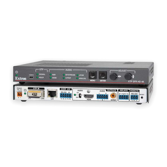
Installation This section contains installation procedures for the XTP SR HD 4K and wiring details. Topics in this section include the following: • Rear Panel Connectors • Connection Details Rear Panel Connectors LINK OVER XTP POWER OUTPUTS RELAYS REMOTE AUDIO AUDIO 1.4 A MAX RS-232... -
Page 14: Xtp Interconnection
XTP Interconnection XTP input connector (see figure 2 on the previous page) — Connect an XTP twisted pair cable transmitter or matrix switcher (see Twisted Pair Cable Termination and Recommendations for XTP Communication on page 9) to the RJ-45 XTP input connector. -
Page 15: Control Connections
Analog audio output connector (see figure 2 on page 5) — Connect a balanced or unbalanced, stereo or mono audio output device to the 3.5 mm, 5-pole captive screw connector for analog audio output (see figure 3 for wiring details). No Ground Here Ring Sleeves... -
Page 16: Power Connection
Power Connection Power connector and LED (see figure 2 on page 5) — Connect the external 12 V, 1.5 A power supply to the 2-pole captive screw connector (see Power Connection on page 12). The Power LED lights to indicate the device is receiving power. It is the same as the front panel Power LED (see figure on page 15). -
Page 17: Twisted Pair Cable Termination And Recommendations For Xtp Communication
Twisted Pair Cable Termination and Recommendations for XTP Communication Use the following pin configurations for twisted pair cables used for XTP communication. Pins: TIA/EIA-T568B 12345678 T568A T568B Wire Color Wire color Wire color White-green White-orange White-orange Green Orange Orange White-orange White-green White-green Blue... -
Page 18: Twisted Pair Cable Termination For Pass-Through Ethernet Communication
NOTE: When using STP cable in bundles or conduits, consider the following: • Do not exceed 40% fill capacity in conduits. • Do not comb the cable for the first 20 m, where cables are straightened, aligned, and secured in tight bundles. •... -
Page 19: Rs-232 And Ir Over Xtp Communication
RS-232 and IR Over XTP Communication The RS-232 and IR Over XTP connector passes serial signals (such as projector control signals) and infrared data. To pass bidirectional serial command signals between XTP-compatible devices, connect a control device to the three poles (Tx, Rx, and G) under “RS-232”... -
Page 20: Power Connection
Power Connection Apply power to the scaling receiver locally with the provided power supply (if necessary, see figure 9 for wiring considerations) or remotely (through the XTP connector) with a power injector or a matrix switcher. Local power 2-Pole Captive Screw Connector Tie Wrap SECTION A–A... - Page 21 WARNING: Electric shock hazard. The two power cord wires must be kept separate while the power supply is plugged in. Remove power before wiring. Avertissement : Risque de choc électrique grave. Les deux cordons d’alimentation doivent être tenus à l’écart l’un de l’autre quand l’alimentation est branchée. Couper l’alimentation avant de faire l’installation électrique.
- Page 22 Remote power The XTP SR HD 4K can be powered remotely through an XTP Power Injector or through an XTP matrix switcher. ATTENTION: • XTP remote power is intended for indoor use only. No part of the network that uses XTP remote power should be routed outdoors.
-
Page 23: Operation
Operation After all transmitters, all receivers, and their connected devices are powered up, the system is fully operational. If any problems are encountered, verify that the cables are routed and connected properly. If problems persist, call the Extron S3 Sales & Technical Support Hotline. -
Page 24: Hdmi Audio Switch
Menu button (see figure 11 on the previous page) — Press this button to navigate the OSD menu or enable or disable front panel lockout mode (see Front Panel Lockout Mode (Executive Mode) on page 25). Enter button — Press this button to navigate the OSD menu or enable or disable front panel lockout mode (see Front Panel Lockout Mode (Executive Mode) on page 25). -
Page 25: On-Screen Display Menu System
On-Screen Display Menu System XTP SR HD 4K configuration and adjustments can be performed by using SIS commands (see SIS Configuration and Control on page 26), the XTP System Configuration Software (see Configuration Software on page 35), or by using the front panel controls and the OSD menu. -
Page 26: Image Reset Submenu
To adjust a submenu item: Navigate to an adjustable submenu item and press the button to select the Enter submenu item. As required, rotate the adjustment knobs or press the button to adjust the Enter submenu item. Press the button to accept the new value. Press the button to cancel any Enter Menu... -
Page 27: Picture Controls Submenu
Picture Controls Submenu submenu allows the adjustment of picture settings. Picture Controls Figure 13. Picture Controls Submenu • Image position — Rotate the knob to adjust the horizontal Horizontal Adjustment (H) position of the image. Rotate the knob to adjust the vertical Vertical Adjustment (V) position of the image. -
Page 28: User Presets Submenu
User Presets Submenu submenu allows the current picture control settings for the selected User Presets input to be saved in user presets. User presets can be saved and recalled later on another input, allowing them to also be used as aspect ratio or discrete size and center shortcuts. There are eight user preset slots available. -
Page 29: Input Configuration Submenu
Input Configuration Submenu submenu displays the total pixels and horizontal and vertical Input Configuration active pixels of the input signal. Figure 15. Input Configuration Submenu Total pixels — Displays the total pixels of the input signal. This is not configurable. •... - Page 30 Resolution — Rotate the adjustment knobs to select a new resolution and refresh rate. • The following table shows the available resolutions and refresh rates. The resolution and Output scaler rate refresh rate can also be changed with SIS commands (see the commands on page 30).
- Page 31 Output format — Shows the HDMI output format setting. This is not configurable from • the OSD menu. To configure this setting, use SIS commands (see HDMI output format SIS commands on page 29) or use the XTP System Configuration Software (see Input/Output tab on page 43).
-
Page 32: Advanced Configuration Submenu
Advanced Configuration Submenu submenu is used to set test patterns, screen blanking and Advanced Configuration freezing, aspect ratio, and system reset. Figure 17. Advanced Configuration Submenu Test pattern — Rotate the adjustment knobs to select a test pattern. The available •... -
Page 33: Front Panel Lockout Mode (Executive Mode)
Front Panel Lockout Mode (Executive Mode) Front Panel Lockout (Executive) mode locks all front panel controls (RS-232 and USB control are still available). To enable or disable executive mode through the front panel, press and hold the buttons simultaneously for about 2 seconds or until the Menu Enter Power LED blinks (see... -
Page 34: Sis Configuration And Control
The following copyright message is displayed after a power cycle via RS-232. (C) Copyright YYYY, Extron Electronics, XTP SR HD 4K Vx.xx, 60-1524-01 is the year. is the firmware version number. -
Page 35: Error Responses
Error Responses When the XTP SR HD 4K receives an SIS command and determines that it is valid, it performs the command and sends the corresponding response to the host device. If the command is determined invalid or contains invalid parameters, the receiver returns an error response to the host. -
Page 36: Command And Response Tables For Sis Commands
Command and Response Tables for SIS Commands Command Name ASCII Command ASCII Response Additional Description (host to XTP) (XTP to host) Picture Control Commands Contrast Set contrast E X! Set the contrast to CONT Cont Increase contrast Increase the contrast level by one. +CONT Cont Decrease contrast... -
Page 37: Output Configuration Commands
Command Name ASCII Command ASCII Response Additional Description (host to XTP) (XTP to host) Horizontal shift Set horizontal shift E X# Set horizontal position to HCTR Hctr Increase horizontal shift Shift the image right by one. +HCTR Hctr Decrease horizontal shift Shift the image left by one. - Page 38 Command Name ASCII Command ASCII Response Additional Description (host to XTP) (XTP to host) Output scaler rate Set output rate Select output resolution and refresh rate. E X& X&] RATE Rate NOTE: Bypass mode outputs the input signal without being scaled like a standard non-scaling receiver. This prevents higher resolutions from being scaled to a lower resolution and potential input and output sync issues in 3D applications.
-
Page 39: Audio Configuration Commands
Command Name ASCII Command ASCII Response Additional Description (host to XTP) (XTP to host) Audio Configuration Commands Volume Set volume Set output volume to Increase volume level by 1 dB Increase the audio volume Decrease volume level by 1 dB Decrease audio volume View volume level View current volume setting. -
Page 40: Preset Commands
Command Name ASCII Command ASCII Response Additional Description (host to XTP) (XTP to host) Preset Commands User presets Recall preset X1)] Recall user preset Save preset X1)] Save the current settings to user preset Advanced Configuration Commands Video mute Mute video to black X1!] Mute the video and dsiplay a black screen. - Page 41 Command Name ASCII Command ASCII Response Additional Description (host to XTP) (XTP to host) Screen saver Set timeout duration E X1% X1^] Set the required duration of SSAV Ssav inactivity before the screen saver activates. View timeout duration X1^] View the required duration of SSAV Ssav inactivity before the screen saver...
-
Page 42: Device Commands
Command Name ASCII Command ASCII Response Additional Description (host to XTP) (XTP to host) Device Commands Relay control Pulse relay X2#] Pulse relay for a duration of Toggle relay X2#] Toggle relay Turn relay on Turn relay Turn relay off Turn relay off. -
Page 43: Configuration Software
Configuration Software This section contains installation and configuration procedures for the XTP System Configuration Software to directly configure and control the XTP SR HD 4K. It can also be configured and controlled remotely through the XTP System Configuration Software and the XTP matrix switcher (see the XTP System Configuration Software Help file). - Page 44 To download and install the XTP System Configuration Software from this page, perform the following: figure On the Extron website, select the tab (see on the previous Download page). On the left sidebar, click the link (see figure Software TIP: If the XTP System Configuration Software is featured in the let sidebar, click link to go directly to the product XTP System Configuration Software...
-
Page 45: Software Product Page
Software Product Page The software product page contains information about the software. Figure 22. XTP System Configuration Software Product Page To download and install the XTP System Configuration Software from this page, perform the following: In the field (see figure 22, ), type Search XTP System Configuration Software... -
Page 46: Software Connection
Software Connection To connect the software directly to the XTP SR HD 4K, connect the computer running the software to the configuration connector (see figure on page 15). Figure 23. Connections Screen To connect to a device: Open the XTP System Configuration Software. The screen opens. -
Page 47: Software Operation
Software Operation Menu Bar The menu bar contains three menus for configuring software settings. File menu menu contains options for disconnecting from the switcher and exiting the File program. To access the menu, click the menu. File Figure 24. File Menu Disconnect This menu item disconnects the connected device from the XTP System Configuration Software. -
Page 48: Update Firmware
Update Firmware This option uploads firmware from the PC to the connected device. If necessary, download firmware from the Extron website (see Firmware Download on page 52). From the menu, select . A dialog box opens to ask permission Tools Update Firmware to disconnect from the device. - Page 49 Help menu menu provides a way to access XTP System Configuration Software information, Help a link to the help file, and a link to the Extron website. Figure 29. Help Menu NOTE: The option is not available when the XTP Tutorial (System Configuration) System Configuration Software is directly connected to the device.
-
Page 50: Device Settings
Device Settings screen allows a user to view and edit various device settings for Device Settings the receiver directly connected to the PC running the XTP software. Click the Device icon (see figure 31, ) on the to open the Settings Global Navigation Bar Device... - Page 51 Input/Output tab Click the tab (see figure 32, ) to open the screen. This Input/Output Input/Output screen contains input and output configurations as well as relay controls. Figure 32. Input/Output Tab Input panel panel on the screen is used to set the aspect ratio. Input Input/Output Aspect Ratio —...
- Page 52 Output panel panel on the screen is used to set the resolution, refresh rate, Output Input/Output and test pattern. Resolution (see figure 32 on the previous page) — From the drop-down Resolution list, select the desired resolution. Refresh Rate — From the drop-down list, select the desired refresh Refresh Rate rate.
- Page 53 Video tab Click the tab to open the screen. This screen contains picture control settings Video Video and user preset management options. Figure 33. Video Tab Picture Control panel panel on the screen is used to adjust brightness, contrast, Picture Control Video and detail settings.
- Page 54 Size and Position tab Click the tab (see figure 34, ) to open the screen. Size/Position Size and Position This screen contains several different ways to adjust the size and position of the output. Figure 34. Size/Position Tab To adjust the size and position graphically: If desired, click the check box ( ) to constrain proportions.
-
Page 55: Audio Tab
Audio tab Click the tab (see figure 35, ) to open the screen. This screen contains Audio Audio audio output settings. Figure 35. Audio Tab Output panel panel on the screen is used to mute or unmute all audio output and Output Audio control volume on the analog audio output. - Page 56 General tab Click the tab (see figure 35, ) to open the screen. This screen contains General General executive mode and video and sync settings. Figure 36. General Tab Executive Mode panel panel on the screen is used to enable or disable front panel Executive Mode General lockout mode (executive mode).
-
Page 57: Factory Reset
Screen Saver panel panel on the screen is used to enable or disable a screen Screen Saver General saver. When enabled, the output sync is disabled after a specified amount of time. Never (see figure 36 on the previous page) — Click the radio button to disable Never the screen saver setting. - Page 58 Device Information panel panel displays device information and signal status information. Device Information Model — Displays the device model. Firmware Version — Displays the current firmware version. Input Signal Present — Displays the signal presence. The indicator to the left turns green when there is an input signal present.
-
Page 59: Reference Information
Reference Information This section contains mounting information and instructions for downloading firmware. Topics in this section include the following: • Mounting • Firmware Download Mounting The XTP SR HD 4K can be placed on a tabletop or mounted in a rack or underneath a desk. -
Page 60: Firmware Download
Reliable earthing (grounding) — Maintain reliable grounding of rack-mounted equipment. Pay particular attention to supply connections other than direct connections to the branch circuit (for example, the use of power strips). Firmware Download Figure 37. Downloading Firmware from the Extron Website On the Extron website, www.extron.com, click the tab (see figure 37, Download... - Page 61 Extron Electronics makes no further warranties either expressed or implied with respect to the product and its quality, performance, merchantability, or fitness for any particular use. In no event will Extron Electronics be liable for direct, indirect, or consequential damages resulting from any defect in this product even if Extron Electronics has been advised of such damage.
Need help?
Do you have a question about the XTP SFR HD 4K and is the answer not in the manual?
Questions and answers