Table of Contents
Advertisement
Quick Links
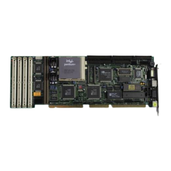
PSC-586VGA
ISA/PCI Pentium™ w/ VGA
Single Board Computer
@Copyright 1996
All Rights Reserved.
Manual first edition May 05,1996
The information in this document is subject to change without prior notice in
order to improve reliability, design and function and does not represent a
commitment on the part of the manufacturer.
In no event will the manufacturer be liable for direct, indirect, special,
incidental, or consequential damages arising out of the use or inability to use
the product or documentation, even if advised of the possibility of such
damages.
This document contains proprietary information protected by copyright. All
rights are reserved. No part of this manual may be reproduced by any
mechanical, electronic, or other means in any form without prior written
permission of the manufacturer.
Trademarks
PSC-586VGA is registered trademarks of Acquire Inc.,IBM PC is a registered
trademark of International Business Machines Corporation. Intel is a
registered trademark of Intel Corporation. AMI is registered trademarks of
American Megatrends, Inc. Other product names mentioned herein are used
for identification purposes only and may be trademarks and/or registered
trademarks of their respective companies.
Advertisement
Table of Contents

Related Manuals for IEI Technology PSC-586VGA


Summary of Contents for IEI Technology PSC-586VGA
- Page 1 Trademarks PSC-586VGA is registered trademarks of Acquire Inc.,IBM PC is a registered trademark of International Business Machines Corporation. Intel is a registered trademark of Intel Corporation. AMI is registered trademarks of American Megatrends, Inc.
-
Page 3: Table Of Contents
Specifications..................4 What You Have..................5 2. Installation..............6 PSC-586VGA's Layout ................6 Unpacking....................8 Jumper Description ................9 Setting the CPU of PSC-586VGA............10 Upgrade the External Cache ..............11 System Memory DRAM ...............11 Watch-Dog Timer.................11 FDC37C665/ALI M5113 Multi-I/O Chip..........12 PCI VGA Controller ................12 3. Connection ..............13 Floppy Disk Drive Connector ...............13... - Page 4 Keyboard Connector................16 External Switches and Indicators ............16 External Speaker..................17 PS/2 Mouse Port .................17 VGA Connector ...................18 4. AMI BIOS Setup............19 Getting Start ..................19 Standard Setup..................20 Advanced Setup ...................21 Chipset Setup..................23 Peripheral Setup...................25 Power Management Setup ..............26 Appendix A. Watch-Dog Timer........27...
-
Page 5: Introduction
An advanced high performance super AT I/O chip SMC FDC37C665 or ALI M5113 is used in the PSC-586VGA board. Both on-chip UARTs are compatible with the NS16C550. The parallel port and IDE interface are compatible with IBM PC/AT and XT architecture's. -
Page 6: Specifications
1.1 Specifications : The PSC-586VGA ISA/PCI Pentium w/ VGA Single Board Computer provides the following specification: • CPU : Pentium 75-166Mhz • : ISA bus and PCI 32-bit local bus • DMA channels : 7 • Interrupt levels : 15 •... -
Page 7: What You Have
±12V @ 15mA ( for RS-232 only) • Operating Temperature : 0° ~ 60° C ( CPU needs Cooler) 1.2 What You Have In addition to this User's Manual , the PSC-586VGA package includes the following items: • PSC-586VGA ISA/PCI Pentium w/ VGA Single Board Computer •... -
Page 8: Installation
Installation This chapter describes how to install the PSC-586VGA. At first, the layout of PSC-586VGA is shown, and the unpacking information that you should be careful is described. The jumpers and switches setting for the PSC-586VGA's configuration, such as CPU type selection, system clock setting, and watch dog timer, are also included. - Page 9 2.2 Unpacking...
-
Page 10: Unpacking
IC's to make sure that they are properly seated. Do this only with the board place on a firm flat surface. Note : DO NOT APPLY POWER TO THE BOARD IF IT HAS BEEN DAMAGED. You are now ready to install your PSC-586VGA Single Board Computer. -
Page 11: Jumper Description
2.3 Jumper Description You can change the PSC-586VGA's configuration by setting jumper switches on the board. The board's jumpers are preset at the factory. Under normal circumstances, you should not need to change the jumper settings. A jumper switch is closed (sometimes referred to as shorted with the plastic cap inserted over two pins of the jumper). -
Page 12: Setting The Cpu Of Psc-586Vga
2.4 Setting the CPU of PSC-586VGA • CPU Clock Setting : CPU Clock/Operation JP10 JP10 50Mhz/ - 75 OPEN OPEN CLOSE CLOSE * 60Mhz/ - 90 OPEN OPEN CLOSE OPEN OPEN OPEN OPEN CLOSE 66Mhz/ -100 60Mhz/ -120 CLOSE OPEN... -
Page 13: Upgrade The External Cache
(*) : default setting 2.5 Upgrade the External Cache The PSC-586VGA designed pipelined burst Cache RAM slot to accept 256KB,512KB,1MB Cache RAM module. The slot is U3. When you install the Cache RAM module, please try to test it before you buy it. Because some Cache RAM module‘s quality and performance is no good,will possible... -
Page 14: Fdc37C665/Ali M5113 Multi-I/O Chip
CLOSE (*) : default setting 2.8 FDC37C665/ALI M5113 Multi-I/O Chip The PSC-586VGA equipped with super multi-I/O chip SMC FDC37C665 or ALI M5113, you can select JP14 or JP15 to enable or disable the multi-I/O Chipset. • JP14/JP15 : Multi-I/O Chipset Setting... -
Page 15: Connection
- 886 2 5147675 Connection This chapter describes how to connect peripherals, switches and indicators to the PSC-586VGA board. 3.1 Floppy Disk Drive Connector PSC-586VGA board equipped with a 34-pin daisy-chain driver connector cable. • CN8 : FDC CONNECTOR PIN NO. DESCRIPTION PIN NO. -
Page 16: Ide Disk Drive Connector
3.2 PCI E-IDE Disk Drive Connector You can attach four IDE( Integrated Device Electronics) hard disk drives to the PSC-586VGA IDE controller. CN7(IDE 1) : Primary IDE Connector CN6(IDE 2) : Secondary IDE Connector • CN6/CN7: IDE Interface Connector PIN NO. -
Page 17: Parallel Port
3.3 Parallel Port This port is usually connected to a printer, The PSC-586VGA includes an on-board parallel port, accessed through a 26-pin flat-cable connector CN10. • CN10 : Parallel Port Connector PIN NO. DESCRIPTION PIN NO. DESCRIPTION STROBE# DATA 0... -
Page 18: Keyboard Connector
• CN13 : Serial Port 10-pin Header( ACE1) Pin No. Description Pin No. Description 3.5 Keyboard Connector The PSC-586VGA provides two keyboard connectors. • CN5 : 5-pin Header Keyboard Connector PIN NO. DESCRIPTION KEYBOARD CLOCK KEYBOARD DATA GROUND • CN15 : 6-pin Mini-DIN Keyboard Connector PIN NO. -
Page 19: External Speaker
• CN4 : IDE LED connector PIN-NO DESCRIPTION HDD ACTIVE# 3.7 External Speaker The PSC-586VGA has its own buzzer, you also can connect to the external speaker through the connector CN2. • CN2 : Speaker Connector PIN NO. DESCRIPTION SPEAKER SIGNAL GROUND 3.8 PS/2 Mouse 6-pin Mini-DIN Connector... -
Page 20: Vga Connector
3.9 VGA Connector The PSC-586VGA built-in 15pin VGA connector directly to your CRT monitor and a 26-pin header Feature Connector for any speical application,for example to drive EL flat panel. • CN11 : 15-pin Female VGA Connector GREEN BLUE GROUND... -
Page 21: Ami Bios Setup
AMI BIOS Setup The PSC-586VGA uses the AMI PCI/ISA BIOS for system configuration. The AMI BIOS setup program is designed to provide maximum flexibility in configuring the system by offering various options which may be selected for end-user requirements. This chapter is written to assist you in the proper usage of these features. -
Page 22: Standard Setup
4.2 Standard Setup The Standard Setup is used for basic hardware system configuration. The main function is for Date/Time setting and Floppy/Hard Disk Drive setting.Please refer the following screen for this setup. Mode Setting for >528MB IDE HDD When the IDE hard disk drive you are using is larger than 528MB,please set the HDD mode to LBA mode. -
Page 23: Advanced Setup
4.3 Advanced Setup This advanced setup is designed for customer‘s tuning best performance of the PSC-586VGA board. As for normal operation customers don‘t have to change any default setting.The default setting is pre-setted for most reliable operation.Please refer the following... -
Page 25: Chipset Setup
System Keyboard : Absent/Present - Will check or not check the keyboard exist when power on system. Primary Display : Absent - Will not check display card when power on system. VGA/EGA,CGA40x25,CGA80x25,or Mono - Options for different display device. Mouse Support : Enable/Disable - Turn on the PS/2 mouse function. - Page 26 AT Bus Clock : 7.16Mhz : The default setting will be fixed at 7.16Mhz bus clock even installed different speed CPU. CLK/4,5,6,8,10,12 : CPU clock(50MHz,60MHz,or 66Mhz,...
-
Page 27: Peripheral Setup
dependent on different CPU speed) divides 4,5,6,8,10,or 12 to get the AT Bus Clock. Parity error check for chipset : Enable/Disalbe : BIOS check the DRAM parity or not. Usually the DRAM module did not have parity function now. 4.5 Peripheral Setup This setup is almost working for Multi-I/O Chip(ALI M5113 or SMC37C665). -
Page 28: Power Management Setup
Serial Port2 : Disable/2F8H/3E8H/2E8H Parallel Port : Disable/3BCH/378H/278H 4.6 Power Management Setup Power Management Setup help user handles the PSC-586VGA board‘s “green” function. The features could shut down the video display and hard disk to save energy for example. The power... -
Page 29: Appendix A. Watch-Dog Timer
Appendix A. Watch-Dog Timer The Watch-Dog Timer is provided to ensure that standalone systems can always recover from catastrophic conditions that caused the CPU to crash. This condition may have occurred by external EMI or a software bug. When the CPU stops working correctly, hardware on the board will either perform a hardware reset (cold boot) or a non- maskable interrupt (NMI) to bring the system back to a known state. - Page 30 be very time consuming. Therefore if the time out period has been set to 10 seconds, the I/O port 443H must be read within 7 seconds. Note: when exiting a program it is necessary to disable the Watch-Dog Timer, otherwise the system will reset.
- Page 31 REM EXAMPLE PROGRAM REM WATCH-DOG TIMER == WDT GOSUB 5000 REM ENABLE AND REFRESH THE WDT GOSUB 1000 REM TASK 1, 2 SECS GOSUB 5000 REFRESH THE WDT GOSUB 2000 REM TASK 2, 3 SECS GOSUB 6000 REM DISABLE THE WDT GOSUB 3000 REM TASK 3, 5 SECS GOSUB 5000 REM ENABLE AND REFRESH THE WDT GOTO 30...
Need help?
Do you have a question about the PSC-586VGA and is the answer not in the manual?
Questions and answers