Advertisement
Quick Links
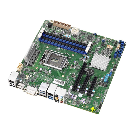
Full-size PICMG 1.3 CPU Card supports LGA1151 Intel® Core™
i7/i5/i3/ Pentium®/Celeron® CPU per Intel® Q370, DDR4, VGA,
DP, Dual Intel® PCIe GbE, SATA 6Gb/s, USB 3.1 Gen 1 (5Gb/s), M.2,
Quick Installation Guide
Package List
PCIE-Q370 package includes the following items:
1 x PCIE-Q370 single board computer
1 x SATA cable
1 x Mini jumper pack
1 x QIG (Quick Installation Guide)
HD Audio, Intel® AMT and RoHS
PCIE-Q370
Version 1.1
June 10, 2019.
©2019 Copyright by IEI Integration corp.
All rights reserved.
Advertisement

Related Manuals for IEI Technology PCIE-Q370


Summary of Contents for IEI Technology PCIE-Q370
- Page 1 HD Audio, Intel® AMT and RoHS PCIE-Q370 Quick Installation Guide Version 1.1 June 10, 2019. Package List PCIE-Q370 package includes the following items: 1 x PCIE-Q370 single board computer 1 x SATA cable 1 x Mini jumper pack ...
-
Page 2: Specifications
Specifications CPU: LGA1151 socket supports 8th generation Intel® Core® i7/i5/i3, Pentium® or Celeron® processor Chipset: Intel® Q370 Memory: Four 288-pin 2666MHz dual-channel DDR4 SDRAM unbuffered DIMMs support up to 64GB BIOS: AMI UEFI BIOS Graphic Engine: Intel®... - Page 3 Front Panel: 1 x Front Panel (Power LED, HDD LED, Speaker, Power Button, Reset Button) LAN LED: 2 x LAN LED (1x2 pin) TPM: 1 x TPM (2x10 pin) SMBus: 1 x SMBus (1x4 pin) I²C: 1 x I²C (1x4 pin) ...
-
Page 4: Ordering Information
All the drivers and One Key Recovery IEI Resource Download Center utility for the PCIE-Q370 are available on https://download.ieiworld.com IEI Resource Download Center. Type PCIE-Q370 and press Enter to find all the relevant software, utilities, and documentation. To install software from the downloaded ISO file, mount the file as a virtual drive to view its content. - Page 5 compatible, 65W CF-1150SC-R20: Special cooler kit for LGA1150, 1U chassis compatible, 65W CF-1150SE-R11: Special cooler kit for LGA1150, 1U chassis compatible, 95W CF-1150SF-R10: Special cooler kit for LGA1150, 1U chassis compatible, 54W SAIDE-KIT01-R10: SATA to IDE/CF Converter board...
-
Page 6: Jumpers Setting And Connectors
Jumpers setting and connectors LABEL FUNCTION J_ATX_AT1 AT/ATX Power Mode Setting J_CMOS2 Clear CMOS Button PCIE x16 Power PCIEX16 Channel Mode Setting USB SW1 Power USB Power Setting USB SW2 Power J_FLASH1 Flash Descriptor Security Override F_PANEL1 Front Panel Connector KB_MS1 6-pin header Keyboard/Mouse Connector DIO1... - Page 7 LED_LAN1 LAN1 link LED Connector LED_LAN2 LAN2 link LED Connector CHASSIS1 Chassis Status Connector J_ATX_AT1: AT/ATX Power Mode Setting PIN NO. DESCRIPTION Short 1 - 2 ATX Mode (default) Short 2 - 3 AT Mode J_CMOS2: Clear CMOS Button PIN NO. DESCRIPTION Keep CMOS Setup NC (default)
- Page 8 USB SW1, USB SW2: USB Power Setting PCIE x16 DESCRIPTION +5V DUAL 5V DUAL (default) Aptio Setup Utility – Copyright (C) 2012 American Megatrends, Inc. Chipset Auto Power Button Status [Disabled(ATX)] Restore AC Power Loss [Last State] ------------------ > PCI Express Configuration >...
- Page 9 KB_MS1: 6-pin header Keyboard/Mouse Connector PIN NO. DESCRIPTION PIN NO. DESCRIPTION Mouse Data Mouse Clock Keyboard Data Keyboard Clock DIO1: Digital Input / Output Connector PIN NO. DESCRIPTION PIN NO. DESCRIPTION Output 3 Output 2 Output 1 Output 0 Input 3 Input 2 Input 1 Input 0...
- Page 10 J_AUDIO1: Audio Source Connector PIN NO. DESCRIPTION PIN NO. DESCRIPTION HDA_BIT_CLK HDA_SYNC HDA_SDOUT HDA_SPKR HDA_SDIN HDA_RST# HDA_GND HDA_VCC HDA_GND HDA_+12V VGA1: VGA Connector PIN NO. DESCRIPTION PIN NO. DESCRIPTION GREEN BLUE DDCDA HSYNC VSYNC DDCCLK HDMI1: HDMI Connector PIN NO. DESCRIPTION PIN NO.
- Page 11 DP1: Internal DisplayPort Connector PIN NO. DESCRIPTION PIN NO. DESCRIPTION DPD_OB_LANE0_P_C DPD_OB_LANE3_N_C DPD_OB_LANE0_N_C AUX_CTRL_DET_D DPD_OB_LANE1_P_C CONFIG2 DPD_AUX_CTRL_P2 DPD_OB_LANE1_N_C DPD_OB_LANE2_P_C DPD_AUX_CTRL_N2 DDI2_HPD# DPD_OB_LANE2_N_C DPD_OB_LANE3_P_C DP PWR TPM1: TPM Connector PIN NO. DESCRIPTION PIN NO. DESCRIPTION LCLK LFRAME# LRERST# LAD3 LAD2 +3.3V LAD1 LAD0 SB3V...
- Page 12 SMB1: SMBUS Connector PIN NO. DESCRIPTION PIN NO. DESCRIPTION SMB_DATA SMB_CLK CN1: EC Debug Connector PIN NO. DESCRIPTION PIN NO. DESCRIPTION EC_EPP_STB# EC_EPP_AFD# EC_EPP_PD0 EC_EPP_PD1 EC_EPP_INIT# EC_EPP_PD2 EC_EPP_SLIN# EC_EPP_PD3 EC_EPP_PD4 EC_EPP_PD5 EC_EPP_BUSY EC_EPP_PD6 EC_EPP_KSI5 EC_EPP_PD7 EC_EPP_KSI4 USB3_34: Internal USB 3.0 Connector PIN NO.
- Page 13 MPCIE1: M-SATA Card Connector PIN NO. DESCRIPTION PIN NO. DESCRIPTION +3.3V +3.3V PCIE_RXN3 PCIE_RXP3 DAS/DSS# PCIE_TXN3 +3.3V PCIE_TXP3 +3.3V +3.3V PCIE_RXN2 +3.3V PCIE_RXP2 PCIE_TXN2 PCIE_TXP2 PCIE_RXN1 PCIE_RXP1 PCIE_TXN1 PCIE_TXP1 DEVSLP PCIE_RXN0 PCIE_RXP0 PCIE_TXN0 PCIE_TXP0 PERST# CLKREQ# REFCLKN PEWAKE REFCLKP Notch Notch Notch Notch...
- Page 14 Notch Notch Notch Notch SUSCLK PEDET +3.3V +3.3V +3.3V USB3_1, USB3_2: External USB 3.0 Connectors PIN NO. DESCRIPTION PIN NO. DESCRIPTION VBUS STDA_SSRX_N STDA_SSRX_P GND_DRAIN STDA_SSTX_N STDA_SSTX_P SATA1, SATA2, SATA3, SATA4, SATA5, SATA6: SATA 6Gb/s Drive Connectors PIN NO. DESCRIPTION PIN NO.
- Page 15 COM4: Internal RS-422/485 Serial Port Connectors PIN NO. DESCRIPTION PIN NO. DESCRIPTION RXD485# RXD485+ TXD485+ TXD485# USB1, USB2, USB4: Internal USB 2.0 Connectors PIN NO. DESCRIPTION PIN NO. DESCRIPTION USB_DATA- USB_DATA+ USB_DATA+ USB_DATA- USB3: External USB 2.0 Connector PIN NO. DESCRIPTION PIN NO.
- Page 16 JSPI2: Flash EC ROM Connector PIN NO. DESCRIPTION PIN NO. DESCRIPTION +3.3V SPI_CS# SPI_SO SPI_CLK SPI_SI LED_LAN1: LAN1 link LED Connector PIN NO. DESCRIPTION PIN NO. DESCRIPTION +3.3V LAN1_LED_LNK#_ACT LED_LAN2: LAN2 link LED Connector PIN NO. DESCRIPTION PIN NO. DESCRIPTION +3.3V LAN2_LED_LNK#_ACT CHASSIS1: Chassis Status Connector...
- Page 17 Board Layout: Jumper and Connector Locations PCIE-Q370-HDMI-R11 SKU...
- Page 19 PCIE-Q370-R11 SKU...
- Page 20 (Unit: mm)
Need help?
Do you have a question about the PCIE-Q370 and is the answer not in the manual?
Questions and answers