Table of Contents

Subscribe to Our Youtube Channel
Related Manuals for IEI Technology PM-PV-N4551/D5251


Summary of Contents for IEI Technology PM-PV-N4551/D5251
- Page 1 PM-PV-N4551/D5251 User Manual MODEL: PM-PV-N4551/D5251 PCI-104 with Intel® Atom™ Processor N455/D525, Ethernet, USB, Audio, RS-232, RS-422/485, SATA, LVDS, CompactFlash®, RoHS Compliant User Manual Page i Rev. 1.02 – August 11, 2016...
- Page 2 PM-PV-N4551/D5251 User Manual Revision Date Version Changes August 11, 2016 1.02 -- Modified Figure 3-10: LAN Connector Location -- Deleted N4251 model information June 10, 2013 1.01 -- Updated Figure 3-13: PCI-104 Connector Location -- Modified Table 3-4: CompactFlash® Slot Pinouts,...
- Page 3 PM-PV-N4551/D5251 User Manual Copyright COPYRIGHT NOTICE The information in this document is subject to change without prior notice in order to improve reliability, design and function and does not represent a commitment on the part of the manufacturer. In no event will the manufacturer be liable for direct, indirect, special, incidental, or consequential damages arising out of the use or inability to use the product or documentation, even if advised of the possibility of such damages.
- Page 4 PM-PV-N4551/D5251 User Manual Manual Conventions WARNING Warnings appear where overlooked details may cause damage to the equipment or result in personal injury. Warnings should be taken seriously. CAUTION Cautionary messages should be heeded to help reduce the chance of losing data or damaging the product.
-
Page 5: Table Of Contents
PM-PV-N4551/D5251 User Manual Table of Contents 1 INTRODUCTION......................1 1.1 I ......................2 NTRODUCTION 1.2 A ......................2 PPLICATIONS 1.3 B ........................2 ENEFITS 1.4 F ........................3 EATURES 1.5 O ........................4 VERVIEW 1.6 C ......................5 ONNECTORS 1.7 D ....................... - Page 6 PM-PV-N4551/D5251 User Manual 3.2.10 LVDS Backlight Inverter Connector .............. 27 3.2.11 PCI-104 Connector ..................27 3.2.12 Power Connector ................... 29 3.2.13 SATA Drive Connectors ................. 30 3.2.14 Serial Port Connector (RS-232)..............31 3.2.15 Serial Port Connector (RS-232/422/485) ............32 3.2.16 USB Connector ....................33 3.2.17 VGA Connector ....................
- Page 7 PM-PV-N4551/D5251 User Manual 5.1.2 Using Setup ...................... 57 5.1.3 Getting Help..................... 58 5.1.4 Unable to Reboot After Configuration Changes..........58 5.1.5 BIOS Menu Bar....................58 5.2 M ........................59 5.3 A ....................... 60 DVANCED 5.3.1 ACPI Settings ....................60 5.3.2 CPU Configuration..................61 5.3.3 SATA Configuration ..................
- Page 8 PM-PV-N4551/D5251 User Manual List of Figures Figure 1–1: PM-PV-N4551/D5251....................2 Figure 1-2: Overview ........................4 Figure 1-3: Solder Side Overview ....................4 Figure 1-4: Dimensions (Top)......................6 Figure 1-5: Dimensions (I/O)......................6 Figure 1-6: Dimensions (Bottom)....................7 Figure 1-7: Data Flow Block Diagram ...................8 Figure 3-1: Connector and Jumper Locations (Front Side) .............16 Figure 3-2: Connector and Jumper Locations (Solder Side) ...........16...
- Page 9 PM-PV-N4551/D5251 User Manual Figure 4-5: CompactFlash® Setup Jumper Location ...............44 Figure 4-6: LVDS Voltage Selection Jumper Locations ............45 Figure 4-7: PCI-104 Voltage Jumper Location................46 Figure 4-8: COM 2 Function Select Jumper Location...............47 Figure 4-9: Keyboard/mouse Y-cable Connection ..............49 Figure 4-10: LVDS Connector......................50 Figure 4-11: Backlight Inverter Connection................51...
- Page 10 PM-PV-N4551/D5251 User Manual List of Tables Table 1-1: Technical Specifications....................10 Table 2-1: Package List Contents ....................14 Table 2-2: Optional Packing List Items..................14 Table 3–1: Internal Peripheral Connectors ................17 Table 3-2: ATX Power Supply Enable Connector Pinouts ............18 Table 3-3: Audio Kit Connector Pinouts..................19 Table 3-4: CompactFlash®...
- Page 11 PM-PV-N4551/D5251 User Manual BIOS Menus BIOS Menu 1: Main ........................59 BIOS Menu 2: Advanced ......................60 BIOS Menu 3: ACPI Settings .......................61 BIOS Menu 4: CPU Configuration ....................62 BIOS Menu 5: IDE Configuration....................63 BIOS Menu 6: USB Configuration ....................64 BIOS Menu 7: Super IO Configuration..................65 BIOS Menu 8: Serial Port n Configuration Menu...............66...
-
Page 13: Introduction
PM-PV-N4551/D5251 User Manual Chapter Introduction Page 1... -
Page 14: Introduction
The PM-PV-N4551/D5251 is particularly suitable for low power and fan-less applications. The PM-PV-N4551/D5251 supports a full range of functions for an AT compatible industrial computer in a space-saving 96 mm x 100 mm profile. The PM-PV-N4551/D5251 is equipped with an on-board low-power consumption and high performance Intel®... -
Page 15: Features
PM-PV-N4551/D5251 User Manual 1.4 Features Some of the PM-PV-N4551/D5251 motherboard features are listed below: Complies with RoHS Embedded Intel® Atom™ D525 or N455 processor Supports a single 204-pin 667/800 MHz DDR3 SO-DIMM (up to 2 GB) ... -
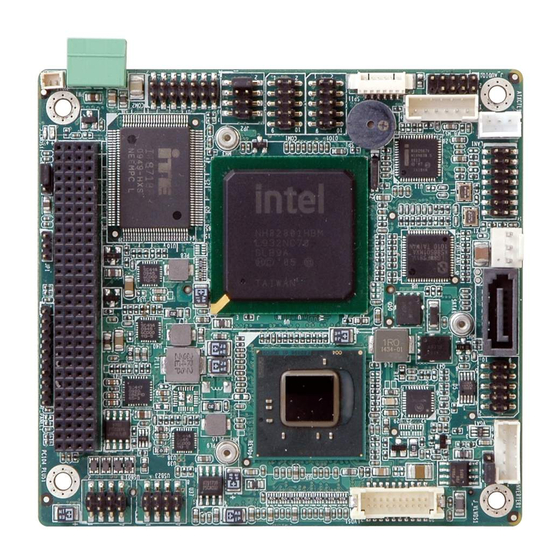
Page 16: Overview
PM-PV-N4551/D5251 User Manual 1.5 Overview Figure 1-2: Overview Figure 1-3: Solder Side Overview Page 4... -
Page 17: Connectors
PM-PV-N4551/D5251 User Manual 1.6 Connectors The PM-PV-N4551/D5251 has the following connectors on-board (described in Chapter 1 x ATX Power Control Connector 1 x Audio Kit Connector 1 x CompactFlash® Slot 1 x Digital I/O Connector ... -
Page 18: Dimensions
PM-PV-N4551/D5251 User Manual 1.7 Dimensions Figure 1-4: Dimensions (Top) Figure 1-5: Dimensions (I/O) Page 6... -
Page 19: Figure 1-6: Dimensions (Bottom)
PM-PV-N4551/D5251 User Manual Figure 1-6: Dimensions (Bottom) Page 7... -
Page 20: Data Flow
PM-PV-N4551/D5251 User Manual 1.8 Data Flow The data flow diagram for the PM-PV-N4551/D5251 is shown below. Figure 1-7: Data Flow Block Diagram Page 8... -
Page 21: Technical Specifications
PM-PV-N4551/D5251 User Manual 1.9 Technical Specifications PM-PV-N4551/D5251 technical specifications are listed in the table below. Specification/Model Description PCI-104 Form Factor Intel® Atom™ processor D525, 1.8 GHz/1 MB L2 cache CPU Options Intel® Atom™ processor D455, 1.66 GHz/512 KB L2 cache Intel®... -
Page 22: Table 1-1: Technical Specifications
PM-PV-N4551/D5251 User Manual Specification/Model Description Operating temperature -20C~60C without cooler, -20C~70C with forced air for D525 processor -20C~70C without cooler, -20C~75C with forced air for N455 processor Humidity 5% ~ 95% non-condensing Dimensions 96 mm x 100 mm Weight GW/NW... -
Page 23: Unpacking
PM-PV-N4551/D5251 User Manual Chapter Unpacking Page 11... -
Page 24: Anti-Static Precautions
Electrostatic discharge (ESD) can cause serious damage to electronic components, including the PM-PV-N4551/D5251. Dry climates are especially susceptible to ESD. It is therefore critical that whenever the PM-PV-N4551/D5251 or any other electrical component is handled, the following anti-static precautions are strictly adhered to. -
Page 25: Packing List
If some of the components listed in the checklist below are missing, please do not proceed with the installation. Contact the IEI reseller or vendor you purchased the PM-PV-N4551/D5251 from or contact an IEI sales representative directly. To contact an IEI sales representative, please send an email to sales@ieiworld.com. -
Page 26: Optional Items
PM-PV-N4551/D5251 User Manual Quantity Item and Part Number Image Power cable (P/N: 32000-130300-RS) VGA cable (P/N:32000-033804-RS) Mini jumper pack Quick Installation Guide Utility CD Table 2-1: Package List Contents 2.4 Optional Items Item and part number Image SATA power cable... -
Page 27: Connectors
PM-PV-N4551/D5251 User Manual Chapter Connectors Page 15... -
Page 28: Peripheral Interface Connectors
PM-PV-N4551/D5251 User Manual 3.1 Peripheral Interface Connectors The locations of the peripheral interface connectors are shown below. 3.1.1 Layout Figure 3-1 shows the on-board peripheral connectors and jumpers on the front side of the board. Figure 3-1: Connector and Jumper Locations (Front Side) Figure 3-2 shows the onboard peripheral connectors on the solder side of the board. -
Page 29: Peripheral Interface Connectors
PM-PV-N4551/D5251 User Manual 3.1.2 Peripheral Interface Connectors The table below shows a list of the peripheral interface connectors on the PM-PV-N4551/D5251. Detailed descriptions of these connectors can be found in the following section. Connector Type Label ATX Power Control Connector... -
Page 30: Internal Peripheral Connectors
3.2 Internal Peripheral Connectors Internal peripheral connectors on the motherboard are only accessible when the motherboard is outside of the chassis. This section has complete descriptions of all the internal, peripheral connectors on the PM-PV-N4551/D5251. 3.2.1 ATX Power Control Connector CN Label:... -
Page 31: Audio Kit Connector
PM-PV-N4551/D5251 User Manual 3.2.2 Audio Kit Connector CN Label: J_AUDIO1 9-pin header (2x5) CN Type: CN Location: See Figure 3-4 CN Pinouts: See Table 3-3 This connector connects to an external audio kit. Figure 3-4: Audio Kit Connector Location Description... -
Page 32: Figure 3-5: Compactflash® Slot Location
PM-PV-N4551/D5251 User Manual A CompactFlash® Type I/II card can be used in this slot. Figure 3-5: CompactFlash® Slot Location Description Description CD1# CE2# IOR# IOW# IRQ14 CSEL# RESET# Page 20... -
Page 33: Digital I/O Connector
PM-PV-N4551/D5251 User Manual Description Description IDE_IORDY# IDE_REQ IDE_DACK# BVD2 BVD1 CD2# Table 3-4: CompactFlash® Slot Pinouts 3.2.4 Digital I/O Connector CN Label: DIO1 CN Type: 10-pin header (2x5) CN Location: See Figure 3-6 See Table 3-5 CN Pinouts: The digital I/O connector provides programmable input and output for external devices. -
Page 34: Fan Connector
PM-PV-N4551/D5251 User Manual Description Description Output 3 Output 2 Output 1 Output 0 Input 3 Input 2 Input 1 Input 0 Table 3-5: Digital I/O Connector Pinouts 3.2.5 Fan Connector CN Label: CPU_FAN1 CN Type: 3-pin wafer (1x3) CN Location:... -
Page 35: Front Panel Connector
PM-PV-N4551/D5251 User Manual 3.2.6 Front Panel Connector CN Label: F_PANEL1 10-pin header (1x10) CN Type: CN Location: See Figure 3-8 CN Pinouts: See Table 3-7 The front panel connector connects to the indicator LEDs and buttons on the computer's front panel. -
Page 36: Keyboard/Mouse Connector
PM-PV-N4551/D5251 User Manual 3.2.7 Keyboard/Mouse Connector CN Label: KB_MS1 6-pin wafer (1x6) CN Type: CN Location: See Figure 3-9 CN Pinouts: See Table 3-8 The keyboard/mouse connector connects to a PS/2 Y-cable that can be connected to a PS/2 keyboard and mouse. -
Page 37: Lan Connector
PM-PV-N4551/D5251 User Manual 3.2.8 LAN Connector CN Label: LAN1 14-pin header (2x7) CN Type: CN Location: See Figure 3-10 CN Pinouts: See Table 3-9 Use LAN cable to connect to LAN1 connector to provide gigabit LAN connection. Figure 3-10: LAN Connector Location... -
Page 38: Lvds Lcd Connector
PM-PV-N4551/D5251 User Manual 3.2.9 LVDS LCD Connector CN Label: LVDS1 20-pin crimp (2x10) CN Type: CN Location: See Figure 3-11 CN Pinouts: See Table 3-10 The LVDS connector is for an LCD panel connected to the board. Figure 3-11: LVDS Connector Location... -
Page 39: Lvds Backlight Inverter Connector
PM-PV-N4551/D5251 User Manual 3.2.10 LVDS Backlight Inverter Connector CN Label: INVERTER1 5-pin wafer (1x5) CN Type: CN Location: See Figure 3-12 CN Pinouts: See Table 3-11 The backlight inverter connector provides power to an LCD panel. Figure 3-12: Backlight Inverter Connector Location... -
Page 40: Figure 3-13: Pci-104 Connector Location
PM-PV-N4551/D5251 User Manual The PCI-104 connector is for installing a PCI-104 expansion card. Figure 3-13: PCI-104 Connector Location Row A Row B Row C Row D GND/5 V TBD1 AD00 VI/O1 AD02 AD01 +5 V AD05 AD04 AD03 C/BE0# AD07... -
Page 41: Power Connector
PM-PV-N4551/D5251 User Manual Row A Row B Row C Row D AD26 AD25 AD29 +5 V AD28 AD27 +5 V AD30 AD31 REQ0# REQ1# VI/O2 REQ2# +5 V GNT0# GNT1# VI/O3 GNT2# +5 V CLK0 CLK1 CLK2 +5 V CLK3... -
Page 42: Sata Drive Connectors
PM-PV-N4551/D5251 User Manual Description +12 V +5 V Table 3-13: Power Connector Pinouts 3.2.13 SATA Drive Connectors CN Label: SATA1 7-pin SATA drive connectors CN Type: CN Location: See Figure 3-15 CN Pinouts: See Table 3-14 The SATA connectors connect to SATA hard drives or optical drives. -
Page 43: Serial Port Connector (Rs-232)
PM-PV-N4551/D5251 User Manual 3.2.14 Serial Port Connector (RS-232) CN Label: COM1 10-pin header (2x5) CN Type: CN Location: See Figure 3-16 CN Pinouts: See Table 3-15 This connector provides RS-232 communications. Figure 3-16: Serial Port Connector Location (COM1) Description Description... -
Page 44: Serial Port Connector (Rs-232/422/485)
PM-PV-N4551/D5251 User Manual 3.2.15 Serial Port Connector (RS-232/422/485) CN Label: COM2 14-pin header (2x7) CN Type: CN Location: See Figure 3-17 CN Pinouts: See Table 3-16 Used for RS-232/422/485 communications. Figure 3-17: Serial Port Connector Location (COM2) Description Description TXD485+... -
Page 45: Usb Connector
PM-PV-N4551/D5251 User Manual 3.2.16 USB Connector CN Label: USB01, USB23 8-pin header (2x4) CN Type: CN Location: See Figure 3-18 CN Pinouts: See Table 3-17 The USB connectors connect to USB devices. Each pin header provides two USB ports. Figure 3-18: USB Connector Pinout Locations... -
Page 46: Figure 3-19: Vga Connector Location
PM-PV-N4551/D5251 User Manual The VGA connector connects to a monitor. Figure 3-19: VGA Connector Location Description Description L_RED 5 V_DDCLK L_GREEN 5 V_DDCDA L_BLUE 5 VHSYNC 5 VVSYNC CRT_PLUG# Table 3-18: VGA Connector Pinouts Page 34... -
Page 47: Installation
PM-PV-N4551/D5251 User Manual Chapter Installation Page 35... -
Page 48: Anti-Static Precautions
Electrostatic discharge (ESD) can cause serious damage to electronic components, including thePM-PV-N4551/D5251. Dry climates are especially susceptible to ESD. It is therefore critical that whenever the PM-PV-N4551/D5251 or any other electrical component is handled, the following anti-static precautions are strictly adhered to. -
Page 49: Installation Considerations
PM-PV-N4551/D5251 User Manual 4.2 Installation Considerations NOTE: The following installation notices and installation considerations should be read and understood before the PM-PV-N4551/D5251 is installed. All installation notices should be strictly adhered to. Failing to adhere to these precautions lead severe... -
Page 50: Installation Checklist
Allow screws to come in contact with the PCB circuit, connector pins, or its components. 4.2.2 Installation Checklist The following checklist is provided to ensure the PM-PV-N4551/D5251 is properly installed. All the items in the packing list are present ... -
Page 51: Unpacking
Follow the anti-static precautions outlined in Section 4.1. Make sure the packing box is facing upwards so the PM-PV-N4551/D5251 does not fall out of the box. Make sure all the components in the unpacking list are present. -
Page 52: So-Dimm Installation
PM-PV-N4551/D5251 User Manual 4.4 SO-DIMM Installation To install an SO-DIMM, please follow the steps below and refer to Figure 4-1. Figure 4-1: SO-DIMM Installation Step 1: Locate the SO-DIMM socket. Place the board on an anti-static mat. Step 2: Align the SO-DIMM with the socket. Align the notch on the memory with the notch on the memory socket. -
Page 53: Jumper Settings
OPEN a jumper means removing the plastic clip from a jumper. Before the PM-PV-N4551/D5251 is installed in the system, the jumpers must be set in accordance with the desired configuration. There are three jumpers on the PM-PV-N4551/D5251. -
Page 54: At/Atx Power Mode Jumper
PM-PV-N4551/D5251 User Manual Connector Type Label AT/ATX Power Mode Jumper 3-pin header Clear CMOS Jumper 3-pin header J_CMOS1 CompactFlash® Setup 3-pin header LVDS Voltage Selection 3-pin header J_LVDS1 PCI-104 Voltage Setup 3-pin header COM 2 Function Select Jumper 6-pin header Table 4–1: Jumper Settings... -
Page 55: Clear Cmos Jumper
PM-PV-N4551/D5251 User Manual Figure 4-3: AT/ATX Power Mode Jumper Location 4.6.2 Clear CMOS Jumper Jumper Label: J_CMOS1 Jumper Type: 3-pin header Jumper Settings: See Table 4-3 Jumper Location: See Figure 4-4 To reset the BIOS, move the jumper to the "Clear BIOS" position for 3 seconds or more, then move back to the default position. -
Page 56: Compactflash® Setup
PM-PV-N4551/D5251 User Manual 4.6.3 CompactFlash® Setup Jumper Label: SW_CF1 switch Jumper Type: See Table 4-4 Jumper Settings: Jumper Location: See Figure 4-5 The CompactFlash® slot is connected through an IDE connection. This switch sets the CompactFlash® card as the master or slave IDE device. -
Page 57: Voltage Setup
PM-PV-N4551/D5251 User Manual Jumper Label: J_VLVDS1 Jumper Type: 3-pin header Jumper Settings: See Table 4-5 Jumper Location: See Figure 4-6 The LCD voltage selection jumper sets the voltage of the power supplied ot the LCD panel. Setting Description +3.3 V +5.0 V... -
Page 58: Com 2 Function Select Jumper
PM-PV-N4551/D5251 User Manual Setting Description +5.0 V +3.3 V Table 4-6: PCI-104 Voltage Jumper Settings Figure 4-7: PCI-104 Voltage Jumper Location 4.6.6 COM 2 Function Select Jumper Jumper Label: Jumper Type: 6-pin header Jumper Settings: See Table 4-7 See Figure 4-8... -
Page 59: Chassis Installation
The PM-PV-N4551/D5251 must be installed in a chassis with ventilation holes on the sides allowing air to flow through the heat sink surface. In a system with an individual power supply unit, the power supply cooling fan can help generate airflow through the board surface. -
Page 60: Internal Peripheral Device Connections
The PM-PV-N4551/D5251 is shipped with a keyboard/mouse Y-cable connector. The keyboard/mouse Y-cable connector connects to a keyboard/mouse connector on the PM-PV-N4551/D5251 and branches into two cables that are each connected to a PS/2 connector, one for a mouse and one for a keyboard. To connect the keyboard/mouse Y-cable connector, please follow the steps below. -
Page 61: Lvds Lcd Installation
Step 0: 4.8.2 LVDS LCD Installation The PM-PV-N4551/D5251 can be connected to a TFT LCD screen through the 30-pin LVDS crimp connector on the board. To connect a TFT LCD to the PM-PV-N4551/D5251, please follow the steps below. Step 1: Locate the connector. -
Page 62: Figure 4-10: Lvds Connector
PM-PV-N4551/D5251 User Manual Step 2: Insert the cable connector. Insert the connector from the LVDS PCB driving board to the LVDS connector as shown in Figure 4-10. When connecting the connectors, make sure the pins are properly aligned. WARNING: The diagram below is merely for illustration. The configuration and connection of the cables from the TFT LCD screen being installed may be different. -
Page 63: Sata Drive Connection
Figure 4-11: Backlight Inverter Connection 4.8.3 SATA Drive Connection The PM-PV-N4551/D5251 is shipped with one SATA drive cable. To connect the SATA drive to the connector, please follow the steps below. Step 1: Locate the connector. -
Page 64: Figure 4-12: Sata Drive Cable Connection
PM-PV-N4551/D5251 User Manual Figure 4-12: SATA Drive Cable Connection Step 3: Connect the cable to the SATA disk. Connect the connector on the other end of the cable to the connector at the back of the SATA drive. See Figure 4-13. -
Page 65: Usb Cable
PM-PV-N4551/D5251 User Manual 4.8.4 USB Cable The PM-PV-N4551/D5251 is shipped with a dual port USB 2.0 cable. To connect the USB cable connector, please follow the steps below. Step 1: Locate the connectors. The locations of the USB connectors are shown in Chapter 3. -
Page 66: Software Installation
PM-PV-N4551/D5251 User Manual 4.9 Software Installation All the drivers for the PM-PV-N4551/D5251 are on the CD that came with the system. To install the drivers, please follow the steps below. Step 1: Insert the CD into a CD drive connected to the system. -
Page 67: Figure 4-16: Available Drivers
PM-PV-N4551/D5251 User Manual Figure 4-16: Available Drivers Step 6: Install all of the necessary drivers in this menu. S t e p 0 : Page 55... -
Page 68: Bios
PM-PV-N4551/D5251 User Manual Chapter BIOS Page 56... -
Page 69: Introduction
PM-PV-N4551/D5251 User Manual 5.1 Introduction The BIOS is programmed onto the BIOS chip. The BIOS setup program allows changes to certain system settings. This chapter outlines the options that can be changed. NOTE: Some of the BIOS options may vary throughout the life cycle of the product and are subject to change without prior notice. -
Page 70: Getting Help
PM-PV-N4551/D5251 User Manual Function F1 key General help, only for Status Page Setup Menu and Option Page Setup Menu F2 key Load previous values. F3 key Load optimized defaults F4 key Save all the CMOS changes Esc key Main Menu – Quit and not save changes into CMOS... -
Page 71: Main
PM-PV-N4551/D5251 User Manual 5.2 Main The Main BIOS menu (BIOS Menu 1) appears when the BIOS Setup program is entered. The Main menu gives an overview of the basic system information. Aptio Setup Utility – Copyright (C) 2010 American Megatrends, Inc. -
Page 72: Advanced
PM-PV-N4551/D5251 User Manual System Time [xx:xx:xx] Use the System Time option to set the system time. Manually enter the hours, minutes and seconds. 5.3 Advanced Use the Advanced menu (BIOS Menu 2) to configure the CPU and peripheral devices... -
Page 73: Cpu Configuration
PM-PV-N4551/D5251 User Manual Aptio Setup Utility – Copyright (C) 2010 American Megatrends, Inc. Advanced ACPI Sleep State [S3 (Suspend to R…)] Set the ACPI state used for System suspend ---------------------- : Select Screen : Select Item Enter Select General Help... -
Page 74: Bios Menu 4: Cpu Configuration
PM-PV-N4551/D5251 User Manual Aptio Setup Utility – Copyright (C) 2010 American Megatrends, Inc. Advanced CPU Configuration Processor Type Intel(R) Atom(TM) CPU CPU D525 @ 1.80GHz ---------------------- EMT64 Supported : Select Screen Processor Speed 1800 MHz : Select Item System Bus Speed... -
Page 75: Sata Configuration
PM-PV-N4551/D5251 User Manual 5.3.3 SATA Configuration Use the SATA Configuration menu (BIOS Menu 5) to change and/or set the configuration of the SATA devices installed in the system. Aptio Setup Utility – Copyright (C) 2010 American Megatrends, Inc. Advanced PATA Master... -
Page 76: Usb Configuration
PM-PV-N4551/D5251 User Manual Configure SATA as [IDE] Use the Configure SATA as option to configure SATA devices as normal IDE devices. Configures SATA devices as normal IDE device. EFAULT AHCI Configures SATA devices as AHCI device. 5.3.4 USB Configuration Use the USB Configuration menu (BIOS Menu 6) to read USB configuration information and configure the USB settings. -
Page 77: Super Io Configuration
PM-PV-N4551/D5251 User Manual Legacy USB Support [Enabled] Use the Legacy USB Support BIOS option to enable USB mouse and USB keyboard support. Normally if this option is not enabled, any attached USB mouse or USB keyboard does not become available until a USB compatible operating system is fully booted with all USB drivers loaded. -
Page 78: Serial Port N Configuration
PM-PV-N4551/D5251 User Manual 5.3.5.1 Serial Port n Configuration Use the Serial Port n Configuration menu (BIOS Menu 8) to configure the serial port n. Aptio Setup Utility – Copyright (C) 2010 American Megatrends, Inc. Advanced Serial Port 0 Configuration Enable or Disable Serial... - Page 79 PM-PV-N4551/D5251 User Manual IO=3F8h; Serial Port I/O port address is 3F8h and the interrupt IRQ=3, address is IRQ3, 4, 5, 6, 7, 10, 11, 12 5, 6, 7, 10, 11, 12 Serial Port I/O port address is 2F8h and the interrupt IO=2F8h;...
- Page 80 PM-PV-N4551/D5251 User Manual Change Settings [Auto] Use the Change Settings option to change the serial port IO port address and interrupt address. Auto The serial port IO port address and interrupt address EFAULT are automatically detected. Serial Port I/O port address is 2F8h and the interrupt IO=2F8h;...
-
Page 81: H/W Monitor
PM-PV-N4551/D5251 User Manual 5.3.6 H/W Monitor The H/W Monitor menu (BIOS Menu 9) shows the operating temperature, fan speeds and system voltages. Aptio Setup Utility – Copyright (C) 2010 American Megatrends, Inc. Advanced PC Health Status CPU Smart Fan control... - Page 82 PM-PV-N4551/D5251 User Manual CPU core 1.05V 3.00V 5.00V 12.0V 1.5VDDR3 1.5V 5VSB VBAT CPU_FAN1 Mode Setting [Full On Mode] Use the Mode Setting option to configure the second fan. Full On Mode Fan is on all the time EFAULT ...
- Page 83 PM-PV-N4551/D5251 User Manual CPU Temperature Limit of ON [040] WARNING: CPU failure can result if this value is set too high When the fan is off, it will only start when the temperature exceeds this setting. Minimum Value: 0°C ...
-
Page 84: Serial Port Console Redirection
PM-PV-N4551/D5251 User Manual 5.3.7 Serial Port Console Redirection The Serial Port Console Redirection menu (BIOS Menu 10) allows the console redirection options to be configured. Console redirection allows users to maintain a system remotely by re-directing keyboard input and text output through the serial port. -
Page 85: Chipset
PM-PV-N4551/D5251 User Manual 5.4 Chipset Use the Chipset menu (BIOS Menu 11) to access the Northbridge and Southbridge configuration menus WARNING! Setting the wrong values for the Chipset BIOS selections in the Chipset BIOS menu may cause the system to malfunction. -
Page 86: Host Bridge Configuration
PM-PV-N4551/D5251 User Manual 5.4.1 Host Bridge Configuration Use the Host Bridge Configuration menu (BIOS Menu 12) to configure the Northbridge chipset. Aptio Setup Utility – Copyright (C) 2010 American Megatrends, Inc. Chipset > OnChip VGA Configuration Select which graphics Initate Graphic Adapter... -
Page 87: Onchip Vga Configuration
PM-PV-N4551/D5251 User Manual 5.4.1.1 OnChip VGA Configuration Use the OnChip VGA Configuration menu (BIOS Menu 12) to configure the OnChip VGA. Aptio Setup Utility – Copyright (C) 2010 American Megatrends, Inc. Chipset OnChip VGA Configuration Select Share Memory Size. Share Memory Size... -
Page 88: South Bridge Configuration
PM-PV-N4551/D5251 User Manual Disabled Disabled the multi-monitor function Enabled the multi-monitor function Enabled EFAULT Initiate Graphic Adapter Use the Initiate Graphic Adapter option to select the graphics controller used as the primary boot device. Select either an integrated graphics controller (IGD) or a combination of PCI graphics controller or an IGD. -
Page 89: Intel Igd Swsci Opregion
PM-PV-N4551/D5251 User Manual Enabled onboard High Definition Audio controller EFAULT automatically detected and enabled The onboard High Definition Audio controller is disabled Disabled USB Function [Enabled] Use the USB Function BIOS option to enable or disable USB function support. -
Page 90: Bios Menu 15:South Bridge Chipset Configuration
PM-PV-N4551/D5251 User Manual Aptio Setup Utility – Copyright (C) 2010 American Megatrends, Inc. Chipset Intel IGD SWSCI OpRegion Configuration Select DVMT Mode/Fixed Mode DVMT Mode Select [DVMT Mode] DVMT/Fixed Memory [256 MB] IGD - Boot Type [VBIOS Default] --------------------- : Select Screen... -
Page 91: Boot
PM-PV-N4551/D5251 User Manual VBIOS Default EFAULT CRT + LFP LCD Panel Type [Select by Panel ID] Use the LCD Panel Type option to select the type of flat panel connected to the system. Configuration options are listed below. -
Page 92: Security
PM-PV-N4551/D5251 User Manual Bootup NumLock State [On] Use the Bootup NumLock State BIOS option to specify if the number lock setting must be modified during boot up. Allows the Number Lock on the keyboard to be EFAULT enabled automatically when the computer system boots up. -
Page 93: Bios Menu 17: Security
PM-PV-N4551/D5251 User Manual Aptio Setup Utility – Copyright (C) 2010 American Megatrends, Inc. Main Advanced Chipset Boot Security Save & Exit Password Description Set Setup Administrator Password If ONLY the Administrator’s password is set, then this only limits access to Setup and is... -
Page 94: Exit
PM-PV-N4551/D5251 User Manual 5.7 Exit Use the Exit menu (BIOS Menu 18) to load default BIOS values, optimal failsafe values and to save configuration changes. Aptio Setup Utility – Copyright (C) 2010 American Megatrends, Inc. Main Advanced Chipset Boot Security Save &... - Page 95 PM-PV-N4551/D5251 User Manual Save as User Defaults Use the Save as User Defaults option to save the changes done so far as user defaults. Restore User Defaults Use the Restore User Defaults option to restore the user defaults to all the setup options.
-
Page 96: A Regulatory Compliance
PM-PV-N4551/D5251 User Manual Appendix Regulatory Compliance Page 84... - Page 97 PM-PV-N4551/D5251 User Manual DECLARATION OF CONFORMITY This equipment has been tested and found to comply with specifications for CE marking. If the user modifies and/or installs other devices in the equipment, the CE conformity declaration may no longer apply. FCC WARNING This equipment complies with Part 15 of the FCC Rules.
-
Page 98: B Product Disposal
PM-PV-N4551/D5251 User Manual Appendix Product Disposal Page 86... - Page 99 PM-PV-N4551/D5251 User Manual CAUTION: Risk of explosion if battery is replaced by an incorrect type. Only certified engineers should replace the on-board battery. Dispose of used batteries according to instructions and local regulations. Outside the European Union–If you wish to dispose of used electrical and electronic products outside the European Union, please contact your local authority so as to comply with the correct disposal method.
-
Page 100: C Bios Options
PM-PV-N4551/D5251 User Manual Appendix BIOS Options Page 88... - Page 101 PM-PV-N4551/D5251 User Manual Below is a list of BIOS configuration options in the BIOS chapter. BIOS Information .........................59 System Date [xx/xx/xx] ......................59 System Time [xx:xx:xx] .......................60 ACPI Sleep State [S3 (Suspend to RAM)]................61 ATA/IDE Configurations [Enhanced] .................63 ...
- Page 102 PM-PV-N4551/D5251 User Manual Bootup NumLock State [On]....................80 Quiet Boot [Enabled] ......................80 Launch PXE OpROM [Disabled] ..................80 Administrator Password .....................81 User Password ........................81 Save Changes and Reset ....................82 Discard Changes and Reset ....................82 ...
-
Page 103: D Terminology
PM-PV-N4551/D5251 User Manual Appendix Terminology Page 91... - Page 104 PM-PV-N4551/D5251 User Manual AC ’97 Audio Codec 97 (AC’97) refers to a codec standard developed by Intel® in 1997. ACPI Advanced Configuration and Power Interface (ACPI) is an OS-directed configuration, power management, and thermal management interface. AHCI Advanced Host Controller Interface (AHCI) is a SATA Host controller register-level interface.
- Page 105 PM-PV-N4551/D5251 User Manual Direct Memory Access (DMA) enables some peripheral devices to bypass the system processor and communicate directly with the system memory. DIMM Dual Inline Memory Modules are a type of RAM that offer a 64-bit data bus and have separate electrical contacts on each side of the module.
- Page 106 PM-PV-N4551/D5251 User Manual Liquid crystal display (LCD) is a flat, low-power display device that consists of two polarizing plates with a liquid crystal panel in between. LVDS Low-voltage differential signaling (LVDS) is a dual-wire, high-speed differential electrical signaling system commonly used to connect LCD displays to a computer.
-
Page 107: E Digital I/O Interface
PM-PV-N4551/D5251 User Manual Appendix Digital I/O Interface Page 95... -
Page 108: Introduction
PM-PV-N4551/D5251 User Manual E.1 Introduction The DIO connector on the PM-PV-N4551/D5251 is interfaced to GPIO ports on the Super I/O chipset. The DIO has both 4-bit digital inputs and 4-bit digital outputs. The digital inputs and digital outputs are generally control signals that control the on/off circuit of external devices or TTL devices. -
Page 109: Assembly Language Sample 1
PM-PV-N4551/D5251 User Manual E.2 Assembly Language Sample 1 AX, 6F08H ;setting the digital port as input AL low byte = value AH – 6FH Sub-function: AL – 9 :Set the digital port as OUTPUT :Digital I/O input value E.3 Assembly Language Sample 2 AX, 6F09H ;setting the digital port as output... -
Page 110: F Watchdog Timer
PM-PV-N4551/D5251 User Manual Appendix Watchdog Timer Page 98... - Page 111 PM-PV-N4551/D5251 User Manual NOTE: The following discussion applies to DOS. Contact IEI support or visit the IEI website for drivers for other operating systems. The Watchdog Timer is a hardware-based timer that attempts to restart the system when it stops working. The system may stop working because of external EMI or software bugs.
- Page 112 PM-PV-N4551/D5251 User Manual NOTE: The Watchdog Timer is activated through software. The software application that activates the Watchdog Timer must also deactivate it when closed. If the Watchdog Timer is not deactivated, the system will automatically restart after the Timer has finished its countdown.
-
Page 113: G Hazardous Materials Disclosure
PM-PV-N4551/D5251 User Manual Appendix Hazardous Materials Disclosure Page 101... - Page 114 PM-PV-N4551/D5251 User Manual The details provided in this appendix are to ensure that the product is compliant with the Peoples Republic of China (China) RoHS standards. The table below acknowledges the presences of small quantities of certain materials in the product, and is applicable to China RoHS only.
- Page 115 PM-PV-N4551/D5251 User Manual 此附件旨在确保本产品符合中国 RoHS 标准。以下表格标示此产品中某有毒物质的含量符 合中国 RoHS 标准规定的限量要求。 本产品上会附有”环境友好使用期限”的标签,此期限是估算这些物质”不会有泄漏或突变”的 年限。本产品可能包含有较短的环境友好使用期限的可替换元件,像是电池或灯管,这些元 件将会单独标示出来。 部件名称 有毒有害物质或元素 铅 汞 镉 六价铬 多溴联苯 多溴二苯 醚 (Pb) (Hg) (Cd) (CR(VI)) (PBB) (PBDE) 壳体 显示 印刷电路板 金属螺帽 电缆组装 风扇组装 电力供应组装 电池 O: 表示该有毒有害物质在该部件所有物质材料中的含量均在 SJ/T 11363-2006 (现由 GB/T 26572-2011 取代) 标准规定的限量要求以下。...
Need help?
Do you have a question about the PM-PV-N4551/D5251 and is the answer not in the manual?
Questions and answers