Table of Contents
Advertisement
Quick Links
Advertisement
Table of Contents

Related Manuals for IEI Technology PCIE-690AM2


Summary of Contents for IEI Technology PCIE-690AM2
- Page 1 PCIE-690AM2 PICMG 1.3 CPU Card Page i...
- Page 2 KINO-LUKE-R20 Half-size CPU Card PCIE-690AM2 PICMG 1.3 CPU Card Revision Date Version Changes 2007-09-21 1.00 Initial release Page ii...
- Page 3 PCIE-690AM2 PICMG 1.3 CPU Card Copyright COPYRIGHT NOTICE The information in this document is subject to change without prior notice in order to improve reliability, design and function and does not represent a commitment on the part of the manufacturer.
- Page 4 Cautionary messages should also be heeded to help reduce the chance of losing data or damaging the PCIE-690AM2. Cautions are easy to recognize. The word “caution” is written as “CAUTION,” both capitalized and bold and is followed. The italicized text is the cautionary message.
- Page 5 PCIE-690AM2 PICMG 1.3 CPU Card CAUTION: This is an example of a caution message. Failure to adhere to cautions messages may result in permanent damage to the PCIE-690AM2. Please take caution messages seriously. NOTE: These messages inform the reader of essential but non-critical information. These messages should be read carefully as any directions or instructions contained therein can help avoid making mistakes.
- Page 6 PCIE-690AM2 from or contact an IEI sales representative directly. To contact an IEI sales representative, please send an email to sales@iei.com.tw. The items listed below should all be included in the PCIE-690AM2 package. 1 x PCIE-690AM2 single board computer 1 x IDE cable...
-
Page 7: Table Of Contents
1.1.1 PCIE-690AM2 Expansion Options ..............2 1.1.2 PCIE-690AM2 Features ..................2 1.2 PCIE-690AM2 O ..................3 VERVIEW 1.2.1 PCIE-690AM2 Overview Photo................. 3 1.2.2 PCIE-690AM2 Peripheral Connectors and Jumpers ........3 1.2.3 Technical Specifications..................4 DETAILED SPECIFICATIONS ................7 2.1 D ......................8 IMENSIONS 2.1.1 Board Dimensions.................... - Page 8 KINO-LUKE-R20 Half-size CPU Card PCIE-690AM2 PICMG 1.3 CPU Card 2.5.5 Interrupt Controller ..................16 2.5.6 DMA Controller ....................16 2.5.7 LPC Host Bus Controller ................. 17 2.5.8 SATA II Controller.................... 17 2.5.9 IDE Controller ....................18 2.5.10 High Definition Audio / AC’97 Audio............18 2.5.11 Timers ......................
- Page 9 PCIE-690AM2 PICMG 1.3 CPU Card 2.10.2 IEI PICMG 1.3 Backplanes ................29 2.10.3 IEI Chassis ..................... 31 UNPACKING ......................33 3.1 A ..................34 STATIC RECAUTIONS 3.2 U ......................34 NPACKING 3.2.1 Unpacking Precautions..................34 3.3 U ................... 35 NPACKING HECKLIST 3.3.1 Package Contents.....................
- Page 10 KINO-LUKE-R20 Half-size CPU Card PCIE-690AM2 PICMG 1.3 CPU Card INSTALLATION ....................69 5.1 A ..................70 STATIC RECAUTIONS 5.2 I ................71 NSTALLATION ONSIDERATIONS 5.2.1 Installation Notices ..................71 5.2.2 Installation Checklist ..................72 5.3 U ......................73 NPACKING 5.3.1 Unpacking Precautions..................73 5.4 CPU, CPU C...
- Page 11 PCIE-690AM2 PICMG 1.3 CPU Card 6.1.3 Getting Help..................... 99 6.1.4 Unable to Reboot After Configuration Changes..........99 6.1.5 BIOS Menu Bar....................99 6.2 M ........................100 6.3 A ......................101 DVANCED 6.3.1 CPU Configuration..................103 6.3.2 IDE Configuration ..................104 6.3.2.1 IDE Master, IDE Slave ................
- Page 12 KINO-LUKE-R20 Half-size CPU Card PCIE-690AM2 PICMG 1.3 CPU Card 7.4 R RTL8110SC G E LAN I ..........167 EALTEK NSTALLATION 7.5 HD A ..............173 UDIO RIVER NSTALLATION 7.5.1 BIOS Setup ..................... 173 7.5.2 Driver Installation ..................174 7.6 W PAM RAID U ..........
- Page 13 PCIE-690AM2 PICMG 1.3 CPU Card List of Figures Figure 1-1: PCIE-690AM2 ......................2 Figure 1-2: PCIE-690AM2 Overview [Front View] ...............3 Figure 2-1: PCIE-690AM2 Dimensions (mm)................8 Figure 2-2: External Interface Panel Dimensions (mm).............8 Figure 2-3: Data Flow Block Diagram..................9 Figure 2-4: Socket AM2.......................10 Figure 2-5: DIMM Sockets......................10...
- Page 14 Figure 4-13: TV Connector Pinout Locations ................60 Figure 4-14: USB Connector Pinout Locations ................61 Figure 4-15: VGA Connector Pinout Locations ................63 Figure 4-16: PCIE-690AM2 External Peripheral Interface Connector........64 Figure 4-17: PS/2 Pinout and Configuration ................64 Figure 4-18: RJ-45 Ethernet Connector..................66 Figure 5-1: Install the CPU......................75...
- Page 15 PCIE-690AM2 PICMG 1.3 CPU Card Figure 7-2: Available Drivers ....................161 Figure 7-3: Chipset Driver Installation Program..............162 Figure 7-4: Chipset Driver Installation Welcome Screen ............. 163 Figure 7-5: Chipset Driver Installation License Agreement ..........163 Figure 7-6: Select Destination Folder..................164 Figure 7-7: Chipset Driver Installing Screen................
- Page 16 KINO-LUKE-R20 Half-size CPU Card PCIE-690AM2 PICMG 1.3 CPU Card Figure 7-34: Chipset Drivers....................179 Figure 7-35: RAID Utility Icon ....................180 Figure 7-36: SATA RAID Setup Program Icon ............... 180 Figure 7-37: Welcome Screen ....................181 Figure 7-38: WebPAM License Agreement ................181 Figure 7-39: Select WebPAM Installation Destination ............
- Page 17 PCIE-690AM2 PICMG 1.3 CPU Card List of Tables Table 1-1: Technical Specifications.....................6 Table 2-1: Power Consumption....................29 Table 2-2: Compatible IEI Backplanes..................30 Table 2-3: Compatible IEI Chassis.....................32 Table 3-1: Package List Contents ....................36 Table 3-2: Package List Contents ....................37 Table 4-1: Peripheral Interface Connectors ................41 Table 4-2: Rear Panel Connectors .....................42...
- Page 18 KINO-LUKE-R20 Half-size CPU Card PCIE-690AM2 PICMG 1.3 CPU Card Table 5-3: IEI Provided Cables ....................83 Table 6-1: BIOS Navigation Keys ....................99 Page xviii...
- Page 19 PCIE-690AM2 PICMG 1.3 CPU Card BIOS Menus Menu 1: Main ..........................100 Menu 2: Advanced........................102 Menu 3: CPU Configuration..................... 103 Menu 4: IDE Configuration ...................... 104 Menu 5: IDE Master and IDE Slave Configuration..............106 Menu 6: IDE Master and IDE Slave Configuration..............111 Menu 7: Super IO Configuration .....................
- Page 20 KINO-LUKE-R20 Half-size CPU Card PCIE-690AM2 PICMG 1.3 CPU Card Glossary AC ’97 Audio Codec 97 Hard Disk Drive ACPI Advanced Configuration and Integrated Data Electronics Power Interface Input/Output Advanced Power Management ICH4 I/O Controller Hub 4 ARMD ATAPI Removable Media Device...
- Page 22 THIS PAGE IS INTENTIONALLY LEFT BLANK Page xxii...
-
Page 23: Introduction
PCIE-690AM2 PICMG 1.3 CPU Card Chapter Introduction Page 1... -
Page 24: Overview
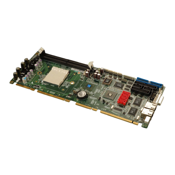
1.1 Overview Figure 1-1: PCIE-690AM2 The PCIE-690AM2 PICMG 1.3 form factor CPU card is a Socket AM2 CPU processor platform. Up to 4GB of DDR2 DIMM SDRAM and up to four SATA II hard disk drives (HDD) are supported. SATA drives can be installed in a RAID 0, RAID 1 or RAID 10 configuration. -
Page 25: Pcie-690Am2 Overview
Supports ATX power supplies 1.2 PCIE-690AM2 Overview 1.2.1 PCIE-690AM2 Overview Photo The PCIE-690AM2 has a wide variety of peripheral interface connectors. Figure 1-2 is a labeled photo of the peripheral interface connectors on the PCIE-690AM2. Figure 1-2: PCIE-690AM2 Overview [Front View] 1.2.2 PCIE-690AM2 Peripheral Connectors and Jumpers... -
Page 26: Technical Specifications
1 x DVI-I connector 1 x PS/2 connector The PCIE-690AM2 has the following on-board jumpers: Clear CMOS 1.2.3 Technical Specifications PCIE-690AM2 technical specifications are listed in Table 1-1. See Chapter 2 for details. Specification PCIE-690AM2 Form Factor PICMG 1.3 AMD Sempron™... - Page 27 PCIE-690AM2 PICMG 1.3 CPU Card Specification PCIE-690AM2 AMD Athlon™ 64 AMD Athlon™ 64 X2 200 MHz, 400 MHz, 600 MHz, 800 MHz and 1000MHz HyperTransport™ Technology HyperTransport™ interfaces supported Northbridge: AMD 690G System Chipset Southbridge: AMD SB600 Two 240-pin DDR2 DIMM sockets support two 2GB...
-
Page 28: Table 1-1: Technical Specifications
PCIE-690AM2 PICMG 1.3 CPU Card Specification PCIE-690AM2 Two RS-232 serial ports Ten USB 2.0 devices supported, six onboard and four on USB2.0 backplane One 40-pin IDE connector connects to two Ultra ATA66/100/133 devices Floppy Disk One 34-pin FDD connector Parallel Port... -
Page 29: Detailed Specifications
PCIE-690AM2 PICMG 1.3 CPU Card Chapter Detailed Specifications Page 7... -
Page 30: Dimensions
PCIE-690AM2 PICMG 1.3 CPU Card 2.1 Dimensions 2.1.1 Board Dimensions The dimensions of the board are listed below: Length: 338.58mm Width: 126.39mm Figure 2-1: PCIE-690AM2 Dimensions (mm) 2.1.2 External Interface Panel Dimensions External peripheral interface connector panel dimensions are shown in Figure 2-2. -
Page 31: Data Flow
Figure 2-3 shows the data flow between the two on-board chipsets and other components installed on the motherboard and described in the following sections of this chapter. Figure 2-3: Data Flow Block Diagram 2.3 Compatible Processors 2.3.1 Supported Processors The PCIE-690AM2 supports the following AMD Socket AM2 processors Page 9... -
Page 32: Ddr2 Memory Controller
AMD Athlon™ 64 X2 processor Figure 2-4: Socket AM2 2.3.2 DDR2 Memory Controller All processors supported by the PCIE-690AM2 CPU card have their own internal DDR2 memory controller. The DDR2 controller has the following features: Low-latency, high-bandwidth 800MHz 128-bit DDR2 SDRAM controller... -
Page 33: Processor Electrical Interfaces
PCIE-690AM2 PICMG 1.3 CPU Card 2.3.3 Processor Electrical Interfaces The supported processors have the following electrical interfaces: HyperTransport™ technology to connect CPU to Northbridge DDR2 SDRAM: SSTL_1.8 per JEDEC specification Clock, reset, and test signals also use DDR2 SDRAM-like electrical specifications. -
Page 34: Acceleration Features
PCIE-690AM2 PICMG 1.3 CPU Card Four PCIe x1 expansion ports One PCIe x4 interface to the Southbridge (A-Link Express II) For further details on the PCIe interfaces, please refer to Section 2.6 on page 21. Figure 2-7: PCIe Interfaces 2.4.2 Acceleration Features... -
Page 35: Display Support
PCIE-690AM2 PICMG 1.3 CPU Card Motion video acceleration features on the AMD 690G include: Enhanced MPEG-2 hardware decode acceleration MPEG-4 decode support Hardware acceleration for WMV9 playback Supports top quality DVD and time-shifted SDTV/HDTV television playback with low CPU usage 2.4.3 Display Support... -
Page 36: Dvi Support
PCIE-690AM2 PICMG 1.3 CPU Card Resolution, refresh rates, and display data can be completely independent for the two display paths Supports both interlaced and non-interlaced displays 2.4.3.3 DVI Support DVI support features include: Supports a TMDS interface, enabling DVI <1650 Mbps/channel with 165 MHz pixel clock rate per link 2.5 AMD SB600 Southbridge Chipset... -
Page 37: Usb Controllers
USB full-speed and low-speed signaling are enabled with the integrated Universal Host Controller Interface (UHCI) controllers. Six of the ten USB ports are implemented on the PCIE-690AM2 CPU card. The remaining four USB ports can be implemented on the backplane. The USB controller supports the... -
Page 38: Smbus Controller
PCIE-690AM2 PICMG 1.3 CPU Card USB 1.1 (“Low Speed”, “Full Speed”) and 2.0 (“High Speed”) ACPI S1~S5 Legacy keyboard/mouse USB debug port Port disable with individual control Figure 2-11: USB Connections 2.5.4 SMBus Controller The AMD SB600 Southbridge chipset SMBus Controller is SMBus Rev. 2.0 compliant and supports SMBALERT # signal / GPIO. -
Page 39: Lpc Host Bus Controller
Supports SPI devices 2.5.8 SATA II Controller The integrated SATA controller on the AMD SB600 Southbridge supports four SATA II drives on the PCIE-690AM2 with independent DMA operations. The SATA controller supports the following: Four SATA ports, complying with SATA 2.0 specifications SATA II 3.0GHz PHY, with backward compatibility with 1.5GHz... -
Page 40: Ide Controller
PCIE-690AM2 PICMG 1.3 CPU Card RAID stripping (RAID 0) across all 4 ports RAID mirroring (RAID 1) across all 4 ports RAID 10 (4 ports needed) Both AHCI mode and IDE mode Advanced power management with AHCI mode Figure 2-13: SATA Connectors 2.5.9 IDE Controller... -
Page 41: Timers
PCIE-690AM2 PICMG 1.3 CPU Card The PCIE-690AM2 onboard audio connector can connect to an optional audio kit through an onboard audio connector. The codec on the optional audio kit is connected to the AMD SB600 audio controller through the High Definition audio / AC’97 audio interface. -
Page 42: Rtc (Real Time Clock)
PCIE-690AM2 PICMG 1.3 CPU Card 2.5.12 RTC (Real Time Clock) 256 bytes of battery backed RAM is provided by the real time clock (RTC) integrated into the AMD SB600. The RTC keeps track of the time and stores system data even when the system is turned off. -
Page 43: Pci Bus Components
PCIE-690AM2 PICMG 1.3 CPU Card 2.6 PCI Bus Components 2.6.1 PCI Bus Overview The PCIE-690AM2 supports the following PCI devices Two PCI GbE connections through two Realtek controllers Four PCI expansion cards on a compatible backplane 2.6.2 PCI Expansion The AMD SB600 Southbridge chipset has four PCI lanes interfaced to PCI slots on compatible backplanes through a golden finger on the bottom of the CPU card. -
Page 44: Realtek Rtl8110Sc Pci Gbe Controller
PCIE-690AM2 PICMG 1.3 CPU Card 2.6.3 RealTek RTL8110SC PCI GbE Controller The AMD SB600 PCI bus is interfaced to a two Realtek RTL8110SC Ethernet controllers, which are then connected to a two RJ-45 connectors. See Figure 2-17. Figure 2-17: Ethernet Interface... -
Page 45: Pcie Bus Components
Figure 2-18: PCIe x16 Edge Connector 2.7.3 PCIe x1 Expansion The PCIE-690AM2 has four PCIe x1 expansion channels interfaced to four PCIe x1 connectors on a backplane through a golden finger on the bottom of the CPU card. Page 23... -
Page 46: Lpc Bus Components
PCIE-690AM2 PICMG 1.3 CPU Card Figure 2-19: PCIe x1 Edge Connector (Four Lanes) 2.8 LPC Bus Components 2.8.1 LPC Bus Overview The LPC bus is connected to components listed below: BIOS chipset Super I/O chipset TPM module connector Figure 2-20: LPC BUS Components... -
Page 47: Bios Chipset
USB booting support 2.8.3 TPM Module A TPM connector on the PCIE-690AM2 is interfaced to the AMD SB600 Southbridge through the LPC bus. The AMD SB600 Southbridge supports TPM version 1.1 and TPM version 1.2 devices for enhanced security. Three TPM modules are available from IEI. -
Page 48: Super I/O Lpc Interface
PCIE-690AM2 PICMG 1.3 CPU Card Two 16C550 UARTs for serial port control One IEEE 1284 Parallel Port Keyboard Controller Watchdog Timer Serial IRQ Support Vbat & Vcch Support Single +5V Power Supply Some of the Super I/O features are described in more detail below: 2.8.4.1 Super I/O LPC Interface... -
Page 49: Super I/O Fan Speed Controller
PCIE-690AM2 PICMG 1.3 CPU Card 2.8.4.4 Super I/O Fan Speed Controller The Super I/O fan speed controller enables the system to monitor the speed of the fan. One of the pins on the fan connector is reserved for fan speed detection and interfaced to the fan speed controller on the Super I/O. -
Page 50: Environmental And Power Specifications
Three thermal inputs on the PCIE-690AM2 Super I/O Enhanced Hardware Monitor monitor the following temperatures: CPU temperature System temperature System temperature 2 Five voltage inputs on the PCIE-690AM2 Super I/O Enhanced Hardware Monitor monitors the following voltages: CPU Core +1.20V +3.3V +5.0V... -
Page 51: Power Consumption
These backplanes and chassis are listed below. 2.10.2 IEI PICMG 1.3 Backplanes The backplanes listed in Table 2-2 are compatible with the PCIE-690AM2 and can be used to develop highly integrated industrial applications. All of the backplanes listed below have 24-pin ATX connector and a 4-pin ATX connector. -
Page 52: Table 2-2: Compatible Iei Backplanes
PCIE-690AM2 PICMG 1.3 CPU Card backplanes please consult the IEI catalog or contact your vendor, reseller or the IEI sales team at sales@iei.com.tw. Expansion Slots System Total Type Model Revision System PCIe Slots PCI-X PE-4S 2.0 or later Single PE-4S2 2.0 or later... -
Page 53: Iei Chassis
PCIE-690AM2 PICMG 1.3 CPU Card 2.10.3 IEI Chassis IEI chassis available for PCIE-690AM2 system development are listed in Table 2-3. For more information about these chassis please consult the IEI catalog or contact your vendor, reseller or the IEI sales team at sales@iei.com.tw. -
Page 54: Table 2-3: Compatible Iei Chassis
PCIE-690AM2 PICMG 1.3 CPU Card Model Slot SBC Mounting Max Slots Backplanes RACK-814G-R20 Full-size (4U) Rack PE-6S-R20 PE-10S-R20 PE-10S2 PXE-13S RACK-3000G-R20 Full-size (4U) Rack PE-6S-R20 PE-10S-R20 PE-10S2 PXE-13S PXE-19S PAC-1700G-R20 Full-size Wall PE-6S-R20 PE-7S PE-7S2 PAC-125G-R20 Full-size Wall PE-6S-R20 PE-8S... -
Page 55: Unpacking
PCIE-690AM2 PICMG 1.3 CPU Card Chapter Unpacking Page 33... -
Page 56: Anti-Static Precautions
Electrostatic discharge (ESD) can cause serious damage to electronic components, including the PCIE-690AM2. Dry climates are especially susceptible to ESD. It is therefore critical that whenever the PCIE-690AM2, or any other electrical component is handled, the following anti-static precautions are strictly adhered to. -
Page 57: Unpacking Checklist
If some of the components listed in the checklist below are missing, please do not proceed with the installation. Contact the IEI reseller or vendor you purchased the PCIE-690AM2 from or contact an IEI sales representative directly. To contact an IEI sales representative, please send an email to sales@iei.com.tw. -
Page 58: Table 3-1: Package List Contents
PCIE-690AM2 PICMG 1.3 CPU Card Quantity Item and Part Number Image SATA cables (P/N: 32000-062800-RS) SATA power cables (P/N: 32100-088600-RS) D-Sub VGA cable with bracket (P/N: 19800-000025-RS) Mini jumper Pack Quick Installation Guide Utility CD USB cable (P/N:CB-USB02-RS) Table 3-1: Package List Contents... -
Page 59: Optional Items
PCIE-690AM2 PICMG 1.3 CPU Card 3.4 Optional Items Item and Part Number Image High Definition Audio kit (P/N: AC-KIT-833HD-R10) CPU cooler (P/N: CF-519-RS) FDD cable (P/N: 32200-000017-RS) LPT cable (P/N:19800-000049-RS) HDTV Cable Set comprises a S-Video cable and a TV-out cable (both items below) - Page 60 PCIE-690AM2 PICMG 1.3 CPU Card THIS PAGE IS INTENTIONALLY LEFT BLANK Page 38...
-
Page 61: Connector Pinouts
PCIE-690AM2 PICMG 1.3 CPU Card Chapter Connector Pinouts Page 39... -
Page 62: Peripheral Interface Connectors
Figure 4-1 shows the on-board peripheral connectors, rear panel peripheral connectors and on-board jumpers. Figure 4-1: Connector and Jumper Locations 4.1.2 Peripheral Interface Connectors Table 4-1 shows a list of the peripheral interface connectors on the PCIE-690AM2. Detailed descriptions of these connectors can be found below. Connector Type... -
Page 63: Table 4-1: Peripheral Interface Connectors
PCIE-690AM2 PICMG 1.3 CPU Card Connector Type Label FDD connector 34-pin box header FDD1 Front panel connector 14-pin header F_PANEL1 IDE Interface connector 40-pin box header Infrared (IrDA) connector 5-pin header Parallel port connector 26-pin box header LPT1 Serial ATA drive connector... -
Page 64: External Interface Panel Connectors
PCIE-690AM2 PICMG 1.3 CPU Card 4.1.3 External Interface Panel Connectors Table 4-2 lists the rear panel connectors on the PCIE-690AM2. Detailed descriptions of these connectors can be found in Section 4.3 on page 64. Connector Type Label DVI connector DVI1... -
Page 65: Figure 4-2: Audio Connector Location (9-Pin)
PCIE-690AM2 PICMG 1.3 CPU Card Figure 4-2: Audio Connector Location (9-pin) PIN NO. DESCRIPTION PIN NO. DESCRIPTION SYNC BITCLK SDOUT PCBEEP SDIN RST# +12V Table 4-3: Audio Connector Pinouts Page 43... -
Page 66: Digital Input/Output (Dio) Connector
PCIE-690AM2 PICMG 1.3 CPU Card 4.2.2 Digital Input/Output (DIO) Connector CN Label: DIO1 10-pin header (2x5) CN Type: CN Location: See Figure 4-3 CN Pinouts: See Table 4-4 The digital input/output connector is managed through a Super I/O chip. The DIO connector pins are user programmable. -
Page 67: Fan Connector (+12V)
PCIE-690AM2 PICMG 1.3 CPU Card PIN NO. DESCRIPTION PIN NO. DESCRIPTION DIOI0 DIOO0 DIOI1 DIOO1 DIOI2 DIOO2 DIOI3 DIOO3 Table 4-4: DIO Connector Pinouts 4.2.3 Fan Connector (+12V) J4 (CPU fan), J1 (System fan) CN Label: CN Type: 3-pin header... -
Page 68: Floppy Disk Connector (34-Pin)
PCIE-690AM2 PICMG 1.3 CPU Card Figure 4-4: +12V Fan Connector Location PIN NO. DESCRIPTION Rotation Signal +12V Table 4-5: +12V Fan Connector Pinouts 4.2.4 Floppy Disk Connector (34-pin) CN Label: FDD1 CN Type: 34-pin header (2x17) Page 46... -
Page 69: Figure 4-5: 34-Pin Fdd Connector Location
PCIE-690AM2 PICMG 1.3 CPU Card See Figure 4-5 CN Location: CN Pinouts: See Table 4-6 The floppy disk connector is connected to a floppy disk drive. Figure 4-5: 34-pin FDD Connector Location PIN NO. DESCRIPTION PIN NO. DESCRIPTION REDUCE WRITE... -
Page 70: Front Panel Connector (14-Pin)
PCIE-690AM2 PICMG 1.3 CPU Card PIN NO. DESCRIPTION PIN NO. DESCRIPTION DRIVE SELECT B# DRIVE SELECT A# MOTOR ENABLE B# DIRECTION# STEP# WRITE DATA# WRITE GATE# TRACK 0# WRITE PROTECT# READ DATA# SIDE 1 SELECT# DISK CHANGE# Table 4-6: 34-pin FDD Connector Pinouts 4.2.5 Front Panel Connector (14-pin) -
Page 71: Figure 4-6: Front Panel Connector Pinout Locations (14-Pin)
PCIE-690AM2 PICMG 1.3 CPU Card Figure 4-6: Front Panel Connector Pinout Locations (14-pin) FUNCTION DESCRIPTION FUNCTION DESCRIPTION Power LED LED+ Speaker SPEAKER+ LED- Power PWRBTSW+ SPEAKER - Button PWRBTSW- Reset HDD LED IDE LED+ RESET+ IDE LED- RESET- Table 4-7: Front Panel Connector Pinouts (14-pin) -
Page 72: Ide Connector (40-Pin)
CN Label: 40-pin header (2x20) CN Type: CN Location: See Figure 4-7 CN Pinouts: See Table 4-8 One 40-pin IDE device connector on the PCIE-690AM2 supports connectivity to two hard disk drives. Figure 4-7: IDE Device Connector Locations Page 50... -
Page 73: Infrared Interface Connector (5-Pin)
PCIE-690AM2 PICMG 1.3 CPU Card PIN NO. DESCRIPTION PIN NO. DESCRIPTION RESET# GROUND DATA 7 DATA 8 DATA 6 DATA 9 DATA 5 DATA 10 DATA 4 DATA 11 DATA 3 DATA 12 DATA 2 DATA 13 DATA 1 DATA 14... -
Page 74: Parallel Port Connector
PCIE-690AM2 PICMG 1.3 CPU Card The infrared interface connector supports both Serial Infrared (SIR) and Amplitude Shift Key Infrared (ASKIR) interfaces. Figure 4-8: Infrared Connector Pinout Locations PIN NO. DESCRIPTION IR-RX IR-TX Table 4-9: Infrared Connector Pinouts 4.2.8 Parallel Port Connector... -
Page 75: Figure 4-9: Parallel Port Connector Location
PCIE-690AM2 PICMG 1.3 CPU Card LPT1 CN Label: CN Type: 26-pin box header CN Location: See Figure 4-9 CN Pinouts: See Table 4-10 The 26-pin parallel port connector connects to a parallel port connector interface or some other parallel port device such as a printer. -
Page 76: Sata Drive Connectors
PCIE-690AM2 PICMG 1.3 CPU Card PIN NO. DESCRIPTION PIN NO. DESCRIPTION STROBE# DATA 0 DATA 1 DATA 2 DATA 3 DATA 4 DATA 5 DATA 6 DATA 7 ACKNOWLEDGE BUSY PAPER EMPTY PRINTER SELECT AUTO FORM FEED # ERROR# INITIALIZE... -
Page 77: Serial Port Connector (Com1, Com 2)
PCIE-690AM2 PICMG 1.3 CPU Card Figure 4-10: SATA Drive Connector Locations PIN NO. DESCRIPTION Table 4-11: SATA Drive Connector Pinouts 4.2.10 Serial Port Connector (COM1, COM 2) CN Label: COM1 and COM2 CN Type: 10-pin header (2x5) Page 55... -
Page 78: Figure 4-11: Serial Connector Pinout Locations
PCIE-690AM2 PICMG 1.3 CPU Card See Figure 4-11 CN Location: CN Pinouts: See Table 4-12 The 10-pin serial port connector provides a second RS-232 serial communications channel. The COM 2 serial port connector can be connected to external RS-232 serial port devices. -
Page 79: Trusted Platform Module (Tpm) Connector
PCIE-690AM2 PICMG 1.3 CPU Card PIN NO. DESCRIPTION PIN NO. DESCRIPTION Transmit Data (TXD) Clear To Send (CTS) Data Terminal Ready (DTR) Ring Indicator (RI) Ground (GND) Ground (GND) Table 4-12: Serial Connector Pinouts 4.2.11 Trusted Platform Module (TPM) Connector... -
Page 80: Figure 4-12: Tpm Connector Pinout Locations
PCIE-690AM2 PICMG 1.3 CPU Card Figure 4-12: TPM Connector Pinout Locations PIN NO. DESCRIPTION PIN NO. DESCRIPTION LCLK GND2 LFRAME# LRESET# LAD3 LAD2 LAD1 LAD0 GND3 SB3V SERIRQ GND1 GLKRUN# Page 58... -
Page 81: Tv Out Connector
PCIE-690AM2 PICMG 1.3 CPU Card PIN NO. DESCRIPTION PIN NO. DESCRIPTION LPCPD# LDRQ# Table 4-13: TPM Connector Pinouts 4.2.12 TV Out Connector CN Label: CN Type: 6-pin header (2x3) CN Location: See Figure 4-13 CN Pinouts: See Table 4-14 The 2x3 pin TV out connector connects to a TV output by using an S-Video or RCA connector. -
Page 82: Usb Connectors (Internal)
PCIE-690AM2 PICMG 1.3 CPU Card Figure 4-13: TV Connector Pinout Locations S-Video Connector PIN NO. DESCRIPTION PIN NO. DESCRIPTION Luminance (Y) Chrominance (Pr) Chrominance (Pb) Table 4-14: TV Port Connector Pinouts 4.2.13 USB Connectors (Internal) Page 60... -
Page 83: Figure 4-14: Usb Connector Pinout Locations
PCIE-690AM2 PICMG 1.3 CPU Card USB1, USB2 and USB3 CN Label: CN Type: 8-pin header (2x4) CN Location: See Figure 4-14 CN Pinouts: See Table 4-15 The 2x4 USB pin connectors each provide connectivity to two USB 1.1 or two USB 2.0 ports. -
Page 84: Vga Connectors (Internal)
PCIE-690AM2 PICMG 1.3 CPU Card PIN NO. DESCRIPTION PIN NO. DESCRIPTION DATAN- DATAM+ DATAN+ DATAM- Table 4-15: USB Port Connector Pinouts 4.2.14 VGA Connectors (Internal) CN Label: CN Type: 10-pin box header (2x5) CN Location: See Figure 4-15 CN Pinouts:... -
Page 85: Figure 4-15: Vga Connector Pinout Locations
PCIE-690AM2 PICMG 1.3 CPU Card Figure 4-15: VGA Connector Pinout Locations PIN NO. DESCRIPTION PIN NO. DESCRIPTION L_RED CRT_DDC_DATA L_GREEN CRT_DDC_CLK L_BLUE 5VHSYNC 5VVSYNC Table 4-16: VGA Connector Pinouts Page 63... -
Page 86: External Peripheral Interface Connector Panel
4.3.1 Keyboard/Mouse Connector CN Label: KB/MS1 CN Type: PS/2 CN Location: See Figure 4-17 (labeled 1) CN Pinouts: See Figure 4-17 Table 4-17 The PCIE-690AM2 keyboard and mouse connector is a standard PS/2 connector. Figure 4-17: PS/2 Pinout and Configuration Page 64... -
Page 87: Dvi Connector
PCIE-690AM2 PICMG 1.3 CPU Card DESCRIPTION KB DATA MS DATA KB CLOCK MS CLOCK Table 4-17: Keyboard Connector Pinouts 4.3.2 DVI Connector CN Label: DVI1 CN Type: DVI-I CN Location: See Figure 4-16 CN Pinouts: See Table 4-18 The 24-pin Digital Visual Interface (DVI) connector connects to high-speed, high-resolution digital displays. -
Page 88: Lan Connectors
CN Pinouts: See Table 4-19 The PCIE-690AM2 is equipped with two built-in RJ-45 Ethernet controllers. The controllers can connect to the LAN through two RJ-45 LAN connectors. There are two LEDs on the connector indicating the status of LAN. The pin assignments are listed in the... -
Page 89: Table 4-20: Rj-45 Ethernet Connector Leds
PCIE-690AM2 PICMG 1.3 CPU Card The RJ-45 Ethernet connector has two status LEDs, one green and one yellow. The green LED indicates activity on the port and the yellow LED indicates the port is linked. See Table 4-20. DESCRIPTION STATUS... - Page 90 PCIE-690AM2 PICMG 1.3 CPU Card THIS PAGE IS INTENTIONALLY LEFT BLANK Page 68...
-
Page 91: Installation
PCIE-690AM2 PICMG 1.3 CPU Card Chapter Installation Page 69... -
Page 92: Anti-Static Precautions
Electrostatic discharge (ESD) can cause serious damage to electronic components, including the PCIE-690AM2. Dry climates are especially susceptible to ESD. It is therefore critical that whenever the PCIE-690AM2, or any other electrical component is handled, the following anti-static precautions are strictly adhered to. -
Page 93: Installation Considerations
PCIE-690AM2 is installed. All installation notices pertaining to the installation of the PCIE-690AM2 should be strictly adhered to. Failing to adhere to these precautions may lead to severe damage of the PCIE-690AM2 and injury to the person installing the motherboard. 5.2.1 Installation Notices... -
Page 94: Installation Checklist
Allow screws to come in contact with the PCB circuit, connector pins, or its components. 5.2.2 Installation Checklist The following checklist is provided to ensure the PCIE-690AM2 is properly installed. All the items in the packing list are present The CPU is installed... -
Page 95: Unpacking
When the PCIE-690AM2 is unpacked, please do the following: Follow the anti-static precautions outlined in Section 5.1. Make sure the packing box is facing upwards so the PCIE-690AM2 does not fall out of the box. Make sure all the components in the checklist shown in Chapter 3 are present. -
Page 96: Cpu, Cpu Cooling Kit And Dimm Installation
Running a CPU without a cooling kit may also result in injury to the user. The CPU, CPU cooling kit and DIMM are the most critical components of the PCIE-690AM2. If one of these components is not installed the PCIE-690AM2 cannot run. 5.4.1 Socket AM2 CPU Installation WARNING: CPUs are expensive and sensitive components. -
Page 97: Figure 5-1: Install The Cpu
PCIE-690AM2 PICMG 1.3 CPU Card Step 1: Inspect the CPU socket. Make sure there are no bent pins and make sure the socket contacts are free of foreign material. If any debris is found, remove it with compressed air. Step 2: Open the CPU socket lever. -
Page 98: Socket Am2 Cooling Kit Installation
PCIE-690AM2 PICMG 1.3 CPU Card 5.4.2 Socket AM2 Cooling Kit Installation CF-AM2-RS CF-478A CF-519-RS Figure 5-2: IEI Cooling Kit An IEI AMD Socket AM2 CPU cooling kit (Figure 5-2) can be purchased separately. The cooling kit comprises a CPU heat sink and a cooling fan. To install the cooling kit, please follow the steps below. -
Page 99: Dimm Installation
5.4.3 DIMM Installation WARNING: Using incorrectly specified DIMM may cause permanently damage the PCIE-690AM2. Please make sure the purchased DIMM complies with the memory specifications of the PCIE-690AM2. DIMM specifications compliant with the PCIE-690AM2 are listed in Chapter 2. To install a DIMM into a DIMM socket, please follow the steps below and refer to Figure 5-4. -
Page 100: Figure 5-4: Installing A Dimm
PCIE-690AM2 PICMG 1.3 CPU Card Figure 5-4: Installing a DIMM Step 1: Open the DIMM socket handles. The DIMM socket has two handles that secure the DIMM into the socket. Before the DIMM can be inserted into the socket, the handles must be opened. See Figure 5-4. -
Page 101: Jumper Settings
OPEN a jumper means removing the plastic clip from a jumper. Before the PCIE-690AM2 is installed in the system, the jumpers must be set in accordance with the desired configuration. The jumpers on the PCIE-690AM2 are listed in Table 5-1. -
Page 102: Table 5-2: Clear Cmos Jumper Settings
PCIE-690AM2 PICMG 1.3 CPU Card If the PCIE-690AM2 fails to boot due to improper BIOS settings, the clear CMOS jumper clears the CMOS data and resets the system BIOS information. To do this, use the jumper cap to close pins 2 and 3 for a few seconds then reinstall the jumper clip back to pins 1 and 2. -
Page 103: Chassis Installation
The PCIE-690AM2 must be installed in a chassis with ventilation holes on the sides allowing airflow to travel through the heat sink surface. In a system with an individual power supply unit, the cooling fan of a power supply can also help generate airflow through the board surface. -
Page 104: Backplane Installation
PCIE-690AM2 PICMG 1.3 CPU Card 5.6.2 Backplane Installation Before the PCIE-690AM2 can be installed into the chassis, a backplane must first be installed. Please refer to the installation instructions that came with the backplane and the chassis to see how to install the backplane into the chassis. -
Page 105: Ata Flat Cable Connection
5.7.2 ATA Flat Cable Connection The ATA 66/100 flat cable connects to the PCIE-690AM2 to one or two IDE devices. To connect an IDE HDD to the PCIE-690AM2 please follow the instructions below. -
Page 106: Audio Kit Installation
5.7.3 Audio Kit Installation An optional audio kit that is separately ordered connects to the 10-pin audio connector on the PCIE-690AM2. To install the audio kit, please refer to the steps below: Step 1: Locate the audio connector. The location of the 10-pin audio connector is shown in Chapter 3. -
Page 107: Fdd Cable Connection
Figure 5-7. Step 0: 5.7.4 FDD Cable Connection The FDD flat cable connects to the PCIE-690AM2 to one FDD device. To connect an FDD to the PCIE-690AM2 please follow the instructions below. Step 1: Locate the FDD connector. The location of the FDD device connector is shown in Chapter 3. -
Page 108: Dual Rs-232 Cable Connection
PCIE-690AM2 PICMG 1.3 CPU Card Figure 5-8: FDD Cable Connection Step 3: Connect the cable to an FDD device. Connect the connector at the other end of the cable to an FDD device. Make sure that pin 1 on the cable corresponds to pin 1 on the connector. -
Page 109: Parallel Port Cable With Slot Bracket
PCIE-690AM2 PICMG 1.3 CPU Card Figure 5-9: Dual RS-232 Cable Installation Step 3: Secure the bracket. The dual RS-232 connector has two D-sub 9 male connectors secured on a bracket. To secure the bracket to the chassis please refer to the reference material that came with the chassis. -
Page 110: Figure 5-10: Lpt Cable Connection
PCIE-690AM2 PICMG 1.3 CPU Card Step 3: Insert the cable connectors. Once the cable connector is properly aligned with the 26-pin box-header connector, connect the cable connector to the onboard connector. See Figure 5-10. Figure 5-10: LPT Cable Connection Step 4: Attach the LPT connector bracket to the chassis. -
Page 111: Sata Drive Connection
Figure 5-11: Connect the LPT Device 5.7.7 SATA Drive Connection The PCIE-690AM2 is shipped with two SATA drive cables and one SATA drive power cable. To connect the SATA drives to the connectors, please follow the steps below. Step 1: Locate the connectors. -
Page 112: Figure 5-12: Sata Drive Cable Connection
PCIE-690AM2 PICMG 1.3 CPU Card Figure 5-12: SATA Drive Cable Connection Step 3: Connect the cable to the SATA disk. Connect the connector on the other end of the cable to the connector at the back of the SATA drive. See Figure 5-13. -
Page 113: Usb Cable (Dual Port)
PCIE-690AM2 PICMG 1.3 CPU Card Figure 5-13: SATA Power Drive Connection 5.7.8 USB Cable (Dual Port) The PCIE-690AM2 is shipped with a dual port USB 2.0 cable. To connect the USB cable connector, please follow the steps below. Step 1: Locate the connectors. -
Page 114: External Peripheral Interface Connection
PCIE-690AM2 PICMG 1.3 CPU Card Step 3: Insert the cable connectors. Once the cable connectors are properly aligned with the USB connectors on the PCIE-690AM2, connect the cable connectors to the onboard connectors. See Figure 5-14. Figure 5-14: Dual USB Cable Connection Step 4: Attach the bracket to the chassis. -
Page 115: Dvi Display Device Connection
PCIE-690AM2 PICMG 1.3 CPU Card 5.8.1 DVI Display Device Connection The PCIE-690AM2 has a single female DVI-I connector on the external peripheral interface panel. The DVI-I connector is connected to a digital display device. To connect a digital display device to the PCIE-690AM2, please follow the instructions below. -
Page 116: Lan Connection (Single Connector)
RJ-45 connector into the onboard RJ-45 connector. Step 0: 5.8.3 PS/2 Y-Cable Connection The PCIE-690AM2 has a PS/2 connector on the external peripheral interface panel. The dual PS/2 connector is connected to the PS/2 Y-cable that came with the PCIE-690AM2. Page 94... -
Page 117: Figure 5-17: Ps/2 Keyboard/Mouse Connector
PCIE-690AM2 PICMG 1.3 CPU Card One of the PS/2 cables is connected to a keyboard and the other to a mouse to the system. Follow the steps below to connect a keyboard and mouse to the PCIE-690AM2. Step 1: Locate the dual PS/2 connector. The location of the PS/2 connector is shown in Chapter 3. - Page 118 PCIE-690AM2 PICMG 1.3 CPU Card THIS PAGE IS INTENTIONALLY LEFT BLANK Page 96...
-
Page 119: Ami Bios
PCIE-690AM2 PICMG 1.3 CPU Card Chapter AMI BIOS Page 97... -
Page 120: Introduction
PCIE-690AM2 PICMG 1.3 CPU Card 6.1 Introduction A licensed copy of AMI BIOS is preprogrammed into the ROM BIOS. The BIOS setup program allows users to modify the basic system configuration. This chapter describes how to access the BIOS setup program and the configuration options that may be changed. -
Page 121: Getting Help
PCIE-690AM2 PICMG 1.3 CPU Card Function F1 key General help, only for Status Page Setup Menu and Option Page Setup Menu F2 /F3 key Change color from total 16 colors. F2 to select color forward. F10 key Save all the CMOS changes, only for Main Menu Table 6-1: BIOS Navigation Keys 6.1.3 Getting Help... -
Page 122: Main
PCIE-690AM2 PICMG 1.3 CPU Card 6.2 Main The Main BIOS menu (BIOS Menu 1) appears when the BIOS Setup program is entered. The Main menu gives an overview of the basic system information. BIOS Menu 1: Main System Overview The System Overview lists a brief summary of different system components. The fields in System Overview cannot be changed. -
Page 123: Advanced
PCIE-690AM2 PICMG 1.3 CPU Card Processor: Displays auto-detected CPU specifications Type: Names the currently installed processor Speed: Lists the processor speed Count: The number of CPUs on the motherboard System Memory: Displays the auto-detected system memory. Size: Lists memory size... - Page 124 PCIE-690AM2 PICMG 1.3 CPU Card ACPI Configuration (see ) Trusted Computing (see Section 6.3.6) Remote Access Configuration (see Section 6.3.8) USB Configuration (see Section 6.3.9) BIOS Menu 2: Advanced Page 102...
-
Page 125: Cpu Configuration
PCIE-690AM2 PICMG 1.3 CPU Card 6.3.1 CPU Configuration Use the CPU Configuration menu (BIOS Menu 3) to view detailed CPU specifications and configure the CPU. BIOS Menu 3: CPU Configuration The CPU Configuration menu (BIOS Menu 3) lists the following CPU details:... -
Page 126: Ide Configuration
PCIE-690AM2 PICMG 1.3 CPU Card Able to Change Freq: Specifies the CPU frequency cannot be changed. uCode Patch Level: 6.3.2 IDE Configuration Use the IDE Configuration menu (BIOS Menu 4) to change and/or set the configuration of the IDE devices installed in the system. - Page 127 PCIE-690AM2 PICMG 1.3 CPU Card controller Primary Only allows the system to detect the Primary IDE channel, including both the Primary Master and Primary Slave) DE Master and IDE Slave When entering setup, BIOS auto detects the presence of IDE devices. BIOS displays the status of the auto detected IDE devices.
-
Page 128: Ide Master, Ide Slave
PCIE-690AM2 PICMG 1.3 CPU Card 6.3.2.1 IDE Master, IDE Slave Use the IDE Master and IDE Slave configuration menu to view both primary and secondary IDE device details and configure the IDE devices connected to the system. BIOS Menu 5: IDE Master and IDE Slave Configuration Auto-Detected Drive Parameters The “grayed-out”... - Page 129 PCIE-690AM2 PICMG 1.3 CPU Card Size: List the storage capacity of the device. LBA Mode: Indicates whether the LBA (Logical Block Addressing) is a method of addressing data on a disk drive is supported or not. Block Mode: Block mode boosts IDE drive performance by increasing the amount of data transferred.
- Page 130 PCIE-690AM2 PICMG 1.3 CPU Card LS-120 LBA/Large Mode [Auto] Use the LBA/Large Mode option to disable or enable BIOS to auto detects LBA (Logical Block Addressing). LBA is a method of addressing data on a disk drive. In LBA mode, the maximum drive capacity is 137 GB.
- Page 131 PCIE-690AM2 PICMG 1.3 CPU Card Auto BIOS auto detects the PIO mode. Use this value if the IDE disk EFAULT drive support cannot be determined. PIO mode 0 selected with a maximum transfer rate of 3.3MBps PIO mode 1 selected with a maximum transfer rate of 5.2MBps PIO mode 2 selected with a maximum transfer rate of 8.3MBps...
- Page 132 PCIE-690AM2 PICMG 1.3 CPU Card MWDMA2 Multi Word DMA mode 2 selected with a maximum data transfer rate of 16.6MBps Ultra DMA mode 0 selected with a maximum data transfer UDMA1 rate of 16.6MBps UDMA1 Ultra DMA mode 1 selected with a maximum data transfer...
-
Page 133: Floppy Configuration
PCIE-690AM2 PICMG 1.3 CPU Card 32Bit Data Transfer [Enabled] Use the 32Bit Data Transfer BIOS option to enables or disable 32-bit data transfers. Disabled Prevents the BIOS from using 32-bit data transfers. Enabled Allows BIOS to use 32-bit data transfers on supported EFAULT hard disk drives. -
Page 134: Super Io Configuration
PCIE-690AM2 PICMG 1.3 CPU Card Disabled 360 KB 51/4” 1.2 MB 51/4” 720 KB 31/2” 1.44 MB 31/2’ 2.88 MB 31/2” 6.3.4 Super IO Configuration Use the Super IO Configuration menu (BIOS Menu 7) to set or change the configurations for the FDD controllers, parallel ports and serial ports. - Page 135 PCIE-690AM2 PICMG 1.3 CPU Card Serial Port1 Address [3F8/IRQ4] Use the Serial Port1 Address option to select the Serial Port 1 base address. Disabled No base address is assigned to Serial Port 1 3F8/IRQ4 Serial Port 1 I/O port address is 3F8 and the interrupt...
- Page 136 PCIE-690AM2 PICMG 1.3 CPU Card 2E8/IRQ3 Serial Port 2 I/O port address is 2E8 and the interrupt address is IRQ3 Serial Port2 Mode [Normal] Use the Serial Port2 Mode option to select the Serial Port2 operational mode. Normal Serial Port 2 mode is normal...
- Page 137 PCIE-690AM2 PICMG 1.3 CPU Card bi-directional communication between the system and the parallel port device and the transmission rates between the two are much faster than the Normal mode. ECP+EPP The parallel port operates in the extended capabilities port (ECP) mode. The ECP mode...
-
Page 138: Hardware Health Configuration
PCIE-690AM2 PICMG 1.3 CPU Card 6.3.5 Hardware Health Configuration The Hardware Health Configuration menu (BIOS Menu 8) shows the operating temperature, fan speeds and system voltages. BIOS Menu 8: Hardware Health Configuration The following system parameters and values are shown. The system parameters that are... - Page 139 PCIE-690AM2 PICMG 1.3 CPU Card CPU Fan Speed System Fan Speed Voltages: The following system voltages are monitored CPU Core +1.20V +3.30V +5.0V +1.8V Page 117...
-
Page 140: Acpi Configuration
PCIE-690AM2 PICMG 1.3 CPU Card 6.3.6 ACPI Configuration Use the General ACPI Configuration menu (BIOS Menu 9) to select the ACPI state when the system is suspended. BIOS Menu 9: ACPI Configuration Suspend Mode [S1(POS)] Use the Suspend Mode option to specify the sleep state the system enters when it is not being used. -
Page 141: Trusted Computing
PCIE-690AM2 PICMG 1.3 CPU Card 6.3.7 Trusted Computing Use the Trusted Computing menu (BIOS Menu 10) to configure settings related to the Trusted Computing Group (TCG) Trusted Platform Module (TPM). BIOS Menu 10: Trusted Computing TCG/TPM Support [Nos] Use the TCG/TPM Support option to configure support for the TPM. -
Page 142: Remote Access Configuration
PCIE-690AM2 PICMG 1.3 CPU Card Clearing the TPM [Press Enter] Use the Clearing the TPM option to clear the information stored in the TPM. 6.3.8 Remote Access Configuration Use the Remote Access Configuration menu (BIOS Menu 11) to configure remote access parameters. - Page 143 PCIE-690AM2 PICMG 1.3 CPU Card Disabled Remote access is disabled. EFAULT Enabled Remote access configuration options shown below appear: Serial Port Number Serial Port Mode Flow Control Redirection after BIOS POST Terminal Type VT-UTF8 Combo Key Support Sredir Memory Display Delay These configuration options are discussed below.
- Page 144 PCIE-690AM2 PICMG 1.3 CPU Card Use the Serial Port Mode option to select baud rate through which the console redirection is made. The following configuration options are available 115200 8,n,1 D EFAULT 57600 8,n,1 38400 8,n,1 19200 8,n,1 09600 8,n,1...
- Page 145 PCIE-690AM2 PICMG 1.3 CPU Card work if set to Always) Terminal Type [ANSI] Use the Terminal Type BIOS option to specify the remote terminal type. ANSI The target terminal type is ANSI EFAULT VT100 The target terminal type is VT100...
-
Page 146: Usb Configuration
PCIE-690AM2 PICMG 1.3 CPU Card 6.3.9 USB Configuration Use the USB Configuration menu (BIOS Menu 12) to read USB configuration information and configure the USB settings. BIOS Menu 12: USB Configuration USB 1.1 OHCI Controller [Enabled] The USB 1.1 OHCI Controller BIOS option enables or disables the USB 1.1 controller Disabled USB 1.1 function disabled... -
Page 147: Usb Mass Storage Device Configuration
PCIE-690AM2 PICMG 1.3 CPU Card The USB 2.0 EHCI Controller BIOS option enables or disables the USB 2.0 controller USB EHCI function disabled Disabled Enabled (Default) USB function enabled Legacy USB Support [Enabled] Use the Legacy USB Support BIOS option to enable USB mouse and USB keyboard support. - Page 148 PCIE-690AM2 PICMG 1.3 CPU Card Use the USB Mass Storage Device Configuration menu (BIOS Menu 13) to configure USB mass storage class devices. BIOS Menu 13: USB Mass Storage Device Configuration USB Mass Storage Reset Delay [20 Sec] Use the USB Mass Storage Reset Delay option to set the number of seconds POST waits for the USB mass storage device after the start unit command.
- Page 149 PCIE-690AM2 PICMG 1.3 CPU Card 30 Sec POST waits 30 seconds for the USB mass storage device after the start unit command. POST waits 40 seconds for the USB mass storage 40 Sec device after the start unit command. Device ## The Device## field lists the USB devices that are connected to the system.
- Page 150 PCIE-690AM2 PICMG 1.3 CPU Card floppy image. This option works only for drives formatted with FAT12, FAT16 or FAT32. Hard Disk Allows the USB device to be emulated as hard disk responding to INT13h calls that return DL values of 80h or above.
-
Page 151: Pci/Pnp
PCIE-690AM2 PICMG 1.3 CPU Card 6.4 PCI/PnP Use the PCI/PnP menu (BIOS Menu 14) to configure advanced PCI and PnP settings. WARNING: Setting wrong values for the BIOS selections in the PCIPnP BIOS menu may cause the system to malfunction. - Page 152 PCIE-690AM2 PICMG 1.3 CPU Card Clear NVRAM [No] Use the Clear NVRAM option to specify if the NVRAM (Non-Volatile RAM) is cleared when the power is turned off. System does not clear NVRAM during system boot EFAULT System clears NVRAM during system boot Plug &...
- Page 153 PCIE-690AM2 PICMG 1.3 CPU Card Allocate IRQ to PCI VGA [Yes] Use the Allocate IRQ to PCI VGA option to restrict the system from giving the VGA adapter card an interrupt address. (Default) Assigns an IRQ to a PCI VGA card if card requests IRQ...
- Page 154 PCIE-690AM2 PICMG 1.3 CPU Card OffBoard PCI/ISA IDE Card [Auto] Use the OffBoard PCI/ISA IDE Card BIOS option to select the OffBoard PCI/ISA IDE Card. Auto The location of the Off Board PCI IDE adapter card is EFAULT automatically detected by the AMIBIOS.
- Page 155 PCIE-690AM2 PICMG 1.3 CPU Card IRQ# [Available] Use the IRQ# address to specify what IRQs can be assigned to a particular peripheral device. Available The specified IRQ is available to be used by EFAULT PCI/PnP devices Reserved The specified IRQ is reserved for use by Legacy ISA...
- Page 156 PCIE-690AM2 PICMG 1.3 CPU Card DM Channel 0 DM Channel 1 DM Channel 3 DM Channel 5 DM Channel 6 DM Channel 7 Reserved Memory Size [Disabled] Use the Reserved Memory Size BIOS option to specify the amount of memory that should be reserved for legacy ISA devices.
-
Page 157: Boot
PCIE-690AM2 PICMG 1.3 CPU Card 6.5 Boot Use the Boot menu (BIOS Menu 15) to configure system boot options. BIOS Menu 15: Boot Page 135... -
Page 158: Boot Settings Configuration
PCIE-690AM2 PICMG 1.3 CPU Card 6.5.1 Boot Settings Configuration Use the Boot Settings Configuration menu (BIOS Menu 16) to configure advanced system boot options. BIOS Menu 16: Boot Settings Configuration Quick Boot [Enabled] Use the Quick Boot BIOS option to make the computer speed up the boot process. - Page 159 PCIE-690AM2 PICMG 1.3 CPU Card Quiet Boot [Disabled] Use the Quiet Boot BIOS option to select the screen display when the system boots. Disabled Normal POST messages displayed EFAULT Enabled OEM Logo displayed instead of POST messages PS/2 Mouse Support [Enabled] Use the PS/2 Mouse Support option adjusts PS/2 mouse support capabilities.
-
Page 160: Boot Device Priority
PCIE-690AM2 PICMG 1.3 CPU Card 6.5.2 Boot Device Priority Use the Boot Device Priority menu (BIOS Menu 17) to specify the boot sequence from the available devices. The following options are available: Boot Device Boot Device BIOS Menu 17: Boot Device Priority Settings... -
Page 161: Hard Disk Drives
PCIE-690AM2 PICMG 1.3 CPU Card 6.5.3 Hard Disk Drives Use the Hard Disk Drives menu to specify the boot sequence of the available HDDs. When the menu is opened, the HDDs connected to the system are listed as shown below:... -
Page 162: Removable Drives
PCIE-690AM2 PICMG 1.3 CPU Card BIOS Menu 18: Hard Disk Drives 6.5.4 Removable Drives Use the Removable Drives menu (BIOS Menu 19) to specify the boot sequence of the available FDDs. When the menu is opened, the FDDs connected to the system are listed... - Page 163 PCIE-690AM2 PICMG 1.3 CPU Card NOTE: Only the drives connected to the system are shown. For example, if only one FDD is connected only “1st Drive” is listed. The boot sequence from the available devices is selected. If the “1st Drive” option is selected a list of available FDDs is shown.
-
Page 164: Security
PCIE-690AM2 PICMG 1.3 CPU Card 6.6 Security Use the Security menu (BIOS Menu 20) to set system and user passwords. BIOS Menu 20: Security Change Supervisor Password Use the Change Supervisor Password to set or change a supervisor password. The default for this option is Not Installed. -
Page 165: Chipset
PCIE-690AM2 PICMG 1.3 CPU Card Use the Change User Password to set or change a user password. The default for this option is Not Installed. If a user password must be installed, select this field and enter the password. After the password has been added, Install appears next to Change User Password. -
Page 166: Northbridge Chipset Configuration
PCIE-690AM2 PICMG 1.3 CPU Card 6.7.1 NorthBridge Chipset Configuration Use the NorthBridge Chipset Configuration menu (BIOS Menu 22) to check the northbridge chipset settings. BIOS Menu 22:NorthBridge Chipset Configuration The NorthBridge Chipset Configuration menu has no configurable options. The NorthBridge Chipset configuration menu shows the following Northbridge chipset settings:... -
Page 167: Ecc Configuration
PCIE-690AM2 PICMG 1.3 CPU Card address strobe) signal. Min Active RAS (Tras): Specifies the speed at which the RAM terminates the access of one row and start accessing another. Row Precharge Time(Trp): Specifies the length of the delay between the activation and precharge commands for the RAS signal. - Page 168 PCIE-690AM2 PICMG 1.3 CPU Card Use the DRAM ECC Enable option to enable the hardware to report and correct memory errors and thereby automatically maintain the system. Disabled System cannot report and correct memory errors Enabled (Default) System can report and correct memory errors 4-Bit ECC Mode Use the 4-Bit ECC Mode to enable or disable the 4-Bit ECC mode (a.k.a.
- Page 169 PCIE-690AM2 PICMG 1.3 CPU Card DRAM scrub off. Disabled (Default) System cannot immediately correct memory errors Enabled System cannot immediately correct memory errors L2 Cache BG Scrub [Disabled] Use the L2 Cache BG Scrub option to enable the system to correct the L2 Data cache when idle.
-
Page 170: Internal Graphics Configuration
PCIE-690AM2 PICMG 1.3 CPU Card 6.7.3 Internal Graphics Configuration Use the Internal Graphics Configuration (BIOS Menu 24) menu to set the integrated graphics. BIOS Menu 24: Internal Graphics Configuration Internal Graphics Mode [UMA] Use the Internal Graphic Mode Select option to how the internal graphics accesses the memory. - Page 171 PCIE-690AM2 PICMG 1.3 CPU Card allocated partition of system memory. UMA Buffer Size [Auto] Use the UMA Buffer Size option to specify the memory to be reserved for the integrated graphics. The following configuration options are available: Auto (Default) 32MB...
- Page 172 PCIE-690AM2 PICMG 1.3 CPU Card otherwise choose automatically. TV Force (Auto) Forces TV the video device if it’s connected, otherwise choose automatically. TV Standard Use the TV Standard option to specify the TV type connected to the system. TV type is set to NTSC...
-
Page 173: Southbridge Configuration
PCIE-690AM2 PICMG 1.3 CPU Card 6.7.4 Southbridge Configuration The Southbridge Configuration menu (BIOS Menu 25) allows the Southbridge chipset to be configured. BIOS Menu 25:SouthBridge Chipset Configuration HD Audio Azalia Device [Disabled] Use the Onboard AC97 Audio DEVICE option to enable or disable the AC’97 CODEC. - Page 174 PCIE-690AM2 PICMG 1.3 CPU Card SB/GPP Port Configuration [PCIE 1X] Use the SB/GPP Port Configuration option to choose whether to use a single PCIe x4 lane or four PCIe x1 lanes. PCIE x1 Four PCIe x1 lanes are enabled. EFAULT A single PCIe x4 lane is enabled.
-
Page 175: Power
PCIE-690AM2 PICMG 1.3 CPU Card 6.8 Power The Power menu (BIOS Menu 26) allows the advanced power management options to be configured. BIOS Menu 26:Power AT/ATX Power [ATX] Use the AT/ATX Power BIOS option to select the power supply that is connected to the system. - Page 176 PCIE-690AM2 PICMG 1.3 CPU Card Power Button Mode [On/Off] Use the Power Button Mode BIOS to specify how the power button functions. On/Off (Default) When the power button is pressed the system is either turned on or off Suspend When the power button is pressed the system goes into...
- Page 177 PCIE-690AM2 PICMG 1.3 CPU Card Disabled (Default) The real time clock (RTC) cannot generate a wake event If selected, the following appears with values that Enabled can be selected: RTC Alarm Date (Days) System Time After setting the alarm, the computer turns itself on from a suspend state when the alarm goes off.
-
Page 178: Exit
PCIE-690AM2 PICMG 1.3 CPU Card 6.9 Exit Use the Exit menu (BIOS Menu 27) to load default BIOS values, optimal failsafe values and to save configuration changes. BIOS Menu 27:Exit Save Changes and Exit Use the Save Changes and Exit option to save the changes made to the BIOS options and to exit the BIOS configuration setup program. - Page 179 PCIE-690AM2 PICMG 1.3 CPU Card Use the Discard Changes and Exit option to exit the BIOS configuration setup program without saving the changes made to the system. Discard Changes Use the Discard Changes option to discard the changes and remain in the BIOS configuration setup program.
- Page 180 PCIE-690AM2 PICMG 1.3 CPU Card THIS PAGE IS INTENTIONALLY LEFT BLANK Page 158...
-
Page 181: Software Drivers
PCIE-690AM2 PICMG 1.3 CPU Card Chapter Software Drivers Page 159... -
Page 182: Available Software Drivers
Audio driver Installation instructions are given below. 7.2 Driver CD Auto-run All the drivers for the PCIE-690AM2 are on the CD that came with the system. To install the drivers, please follow the steps below. Step 1: Insert the CD into a CD drive connected to the system. -
Page 183: Figure 7-1: Introduction Screen
PCIE-690AM2 PICMG 1.3 CPU Card Figure 7-1: Introduction Screen Step 3: Click PCIE-690AM2. Step 4: A new screen with a list of available drivers appears (Figure 7-2). Figure 7-2: Available Drivers Step 5: Select the driver to install from the list in Figure 7-2. Detailed driver installation instructions follow below. -
Page 184: Amd Sb600 Chipset Driver Installation
PCIE-690AM2 PICMG 1.3 CPU Card 7.3 AMD SB600 Chipset Driver Installation To install the chipset driver, please follow the steps below. NOTE: The chipset driver control center requires Microsoft .NET Framework prior to installation. The driver control center is an application that allows a user to control the configuration of the AMD product. -
Page 185: Figure 7-4: Chipset Driver Installation Welcome Screen
PCIE-690AM2 PICMG 1.3 CPU Card Step 4: The screen in Figure 7-4 appears. Figure 7-4: Chipset Driver Installation Welcome Screen Step 5: Open the SB600 directory. The screen in Figure 7-5 appears. Figure 7-5: Chipset Driver Installation License Agreement Step 6: The screen in Figure 7-6 appears. -
Page 186: Figure 7-6: Select Destination Folder
PCIE-690AM2 PICMG 1.3 CPU Card Figure 7-6: Select Destination Folder Step 7: Click install to continue. Step 8: The screen in Figure 7-7 appears as the driver starts to install. Figure 7-7: Chipset Driver Installing Screen Step 9: The welcome screen shown in Figure 7-8 appears. -
Page 187: Figure 7-8: Welcome Screen
PCIE-690AM2 PICMG 1.3 CPU Card Figure 7-8: Welcome Screen Step 10: Click Y to continue. Step 11: The License agreement file in Figure 7-9 appears. Figure 7-9: Chipset Driver Readme File Information Step 12: Click Y to continue. Step 13: The screen in Figure 7-10 appears. -
Page 188: Figure 7-10: Chipset Driver Installation Complete
PCIE-690AM2 PICMG 1.3 CPU Card Figure 7-10: Chipset Driver Installation Complete Step 14: Select the installation type (Express or Custom) then click Next to continue. Step 15: The installer starts to load the display driver. Step 16: Next the WDM Capture drivers load (for VIVO or All-In-Wonder) Step 17: The Catalyst Control Center setup starts shortly after. -
Page 189: Realtek Rtl8110Sc Gbe Lan Installation
PCIE-690AM2 PICMG 1.3 CPU Card Figure 7-11: Setup Complete Step 20: To complete the installation, click Finish. Step 0: 7.4 Realtek RTL8110SC GbE LAN Installation To install the Realtek RTL8110SC LAN driver, please follow the steps below. Step 1: Select LAN from the list in Figure 7-2. -
Page 190: Figure 7-13: Realtek Folder
PCIE-690AM2 PICMG 1.3 CPU Card Figure 7-13: Realtek Folder Step 4: Double-click the Realtek folder and a new window opens (Figure 7-14). Figure 7-14: RTL8110SC Folder Step 5: Double-click the appropriate OS folder and a new window opens (Figure 7-15). -
Page 191: Figure 7-15: Windows Folder
PCIE-690AM2 PICMG 1.3 CPU Card Figure 7-15: Windows Folder Step 6: Double-click the WIN98_ME_2K_XP_XP64 folder and a new window opens (Figure 7-16). Figure 7-16: WIN98_ME_2K_XP_XP64 Folder Step 7: Double-click the PCI_InstallShield_5649_060_919 folder and a new window opens (Figure 7-17). Page 169... -
Page 192: Figure 7-17: Pci_Installshield_5649_060_919 Folder
PCIE-690AM2 PICMG 1.3 CPU Card Figure 7-17: PCI_InstallShield_5649_060_919 Folder Step 8: Double-click the setup.exe program icon. Step 9: The InstallShield Wizard is prepared to guide the user through the rest of the process (Figure 7-18). Figure 7-18: RTL8110SC InstallShield Wizard Step 10: The InstallShield Wizard continues (Figure 7-19). -
Page 193: Figure 7-19: Rtl8110Sc Installshield Wizard Continues
PCIE-690AM2 PICMG 1.3 CPU Card Figure 7-19: RTL8110SC InstallShield Wizard Continues Step 11: Once initialized, the InstallShield Wizard welcome screen appears (Figure 7-20). Figure 7-20: RTL8110SC InstallShield Wizard Welcome Screen Step 12: Click N to continue the installation. Step 13: The InstallShield Wizard is ready to install the driver (Figure 7-21). -
Page 194: Figure 7-21: Rtl8110Sc Driver Ready Screen
PCIE-690AM2 PICMG 1.3 CPU Card Figure 7-21: RTL8110SC Driver Ready Screen Step 14: Click I to continue the installation process. NSTALL Step 15: InstallShield starts to install the new software (Figure 7-22). Figure 7-22: RTL8110SC Drivers Installing Step 16: The InstallShield Wizard continues (Figure 7-23). -
Page 195: Hd Audio Kit Driver Installation
PCIE-690AM2 PICMG 1.3 CPU Card Figure 7-23: RTL8110SC InstallShield Wizard Step 17: After the driver installation process is complete, a confirmation screen appears (Figure 7-24). Figure 7-24: RTL8110SC Driver Installation Complete Step 18: Click F to exit the program. Step 0: INISH 7.5 HD Audio Kit Driver Installation... -
Page 196: Driver Installation
PCIE-690AM2 PICMG 1.3 CPU Card 7.5.2 Driver Installation To install the audio driver please follow the steps below. Step 1: Select AUDIO from the list in Figure 7-2. Step 2: A new window opens (Figure 7-25). Figure 7-25: Select the Audio CODEC Step 3: Double-click the ALC665 folder. -
Page 197: Figure 7-26: Locate The Setup Program Icon
PCIE-690AM2 PICMG 1.3 CPU Card Figure 7-26: Locate the Setup Program Icon Step 5: The InstallShield Wizard is prepared to guide the user through the rest of the process (Figure 7-27). Figure 7-27: Preparing Setup Screen Step 6: Once initialized, the InstallShield Wizard welcome screen appears (Figure 7-28). -
Page 198: Figure 7-28: Installshield Wizard Welcome Screen
PCIE-690AM2 PICMG 1.3 CPU Card Figure 7-28: InstallShield Wizard Welcome Screen Step 7: Click N to continue the installation. Step 8: InstallShield starts to install the new software as shown in Figure 7-29. Figure 7-29: Audio Driver Software Configuration Step 9: At this stage the Digital Signal Not Found screen shown in Figure 7-30 appears. -
Page 199: Figure 7-30: Audio Driver Digital Signal
PCIE-690AM2 PICMG 1.3 CPU Card Figure 7-30: Audio Driver Digital Signal Step 10: Click Y and the driver installation begins (Figure 7-31). Figure 7-31: Audio Driver Installation Step 11: After the driver installation process is complete, a confirmation screen appears (Figure 7-32). -
Page 200: Webpam Raid Utility Driver Installation
PCIE-690AM2 PICMG 1.3 CPU Card Figure 7-32: Restart the Computer Step 12: The confirmation screen offers the option of restarting the computer now or later. For the settings to take effect, the computer must be restarted. Click F INISH restart the computer. -
Page 201: Figure 7-33: Chipset Driver Installation Program
PCIE-690AM2 PICMG 1.3 CPU Card Figure 7-33: Chipset Driver Installation Program Step 3: Double-click the directory icon for the operating system that is running on the system. Step 4: The screen in Figure 7-34 appears. Figure 7-34: Chipset Drivers Step 5: Open the RAID Utility from directory in Figure 7-34. -
Page 202: Figure 7-35: Raid Utility Icon
PCIE-690AM2 PICMG 1.3 CPU Card Step 6: A new window opens (Figure 7-35). Figure 7-35: RAID Utility Icon Step 7: Double-click the Icon Figure 7-35. Step 8: The RAID Utility installation procedure is initiated as shown in Figure 7-36. Figure 7-36: SATA RAID Setup Program Icon Step 9: The welcome screen in Figure 7-37 appears. -
Page 203: Figure 7-37: Welcome Screen
PCIE-690AM2 PICMG 1.3 CPU Card Figure 7-37: Welcome Screen Step 10: Click Next to continue. Step 11: The license agreement shown in Figure 7-38 appears. Figure 7-38: WebPAM License Agreement Step 12: Click Next to continue. Page 181... -
Page 204: Figure 7-39: Select Webpam Installation Destination
PCIE-690AM2 PICMG 1.3 CPU Card Step 13: The screen in Figure 7-39 appears. Figure 7-39: Select WebPAM Installation Destination Step 14: Select the destination for the WebPAM. Click N to continue. Step 15: The Ready to Install Program screen in Figure 7-40 appears. -
Page 205: Figure 7-41: Webpam Installation
PCIE-690AM2 PICMG 1.3 CPU Card Step 17: The WebPAM program begins to install as shown in Figure 7-41. Figure 7-41: WebPAM Installation Step 18: The Installation complete screen in Figure 7-42 appears. Figure 7-42: WebPAM Installation Complete Step 19: Click Finish to complete WebPAM installation. - Page 206 PCIE-690AM2 PICMG 1.3 CPU Card THIS PAGE IS INTENTIONALLY LEFT BLANK Page 184...
-
Page 207: Abios Options
PCIE-690AM2 PICMG 1.3 CPU Card Appendix BIOS Options Page 185... - Page 208 PCIE-690AM2 PICMG 1.3 CPU Card System Overview ......................100 System Time [hh:mm:ss]..................... 101 System Date [dd/mm/yyyy]..................101 OnBoard PCI IDE Controller [Both] ................104 DE Master and IDE Slave ..................... 105 Auto-Detected Drive Parameters ................106 Type [Auto]........................107 ZIP ..........................108 LS-120 ..........................
- Page 209 PCIE-690AM2 PICMG 1.3 CPU Card VT-UTF8 Combo Key Support ..................121 Sredir Memory Display Delay ..................121 Serial Port Number [COM1] ..................121 Base Address, IRQ [3F8h,4] ..................121 Serial Port Mode [115200 8,n,1]................... 121 Flow Control [None] ..................... 122 Redirection After BIOS POST [Always]..............
- Page 210 PCIE-690AM2 PICMG 1.3 CPU Card Change User Password ....................142 DRAM ECC Enable [Enabled] ..................145 4-Bit ECC Mode......................146 DRAM SCRUB REDIRECT [Disabled] ................. 146 DRAM BG Scrub [Disabled]..................146 L2 Cache BG Scrub [Disabled]..................147 L1 Cache BG Scrub [Disabled]..................147 Internal Graphics Mode [UMA] ..................
-
Page 211: Bdio Interface
PCIE-690AM2 PICMG 1.3 CPU Card Appendix DIO Interface Page 189... -
Page 212: Dio Interface Introduction
PCIE-690AM2 PICMG 1.3 CPU Card B.1 DIO Interface Introduction The DIO connector on the PCIE-690AM2 is interfaced to GIO ports on the iTE Super I/O chipset. The DIO has both 4-bit digital inputs and 4-bit digital outputs. The digital inputs and digital outputs are generally control signals that control the on/off circuit of external devices or TTL devices. -
Page 213: Assembly Language Samples
PCIE-690AM2 PICMG 1.3 CPU Card B.3 Assembly Language Samples B.3.1 Enable the DIO Input Function The BIOS interrupt call INT 15H controls the digital I/O. An assembly program to enable digital I/O input functions is listed below. AX, 6F08H Sets the digital port as input Initiates the INT 15H BIOS call B.3.2 Enable the DIO Output Function... - Page 214 PCIE-690AM2 PICMG 1.3 CPU Card THIS PAGE IS INTENTIONALLY LEFT BLANK Page 192...
-
Page 215: Cwatchdog Timer
PCIE-690AM2 PICMG 1.3 CPU Card Appendix Watchdog Timer Page 193... - Page 216 PCIE-690AM2 PICMG 1.3 CPU Card NOTE: The following discussion applies to DOS environment. IEI support is contacted or the IEI website visited for specific drivers for more sophisticated operating systems, e.g., Windows and Linux. The Watchdog Timer is provided to ensure that standalone systems can always recover from catastrophic conditions that cause the CPU to crash.
- Page 217 PCIE-690AM2 PICMG 1.3 CPU Card NOTE: When exiting a program it is necessary to disable the Watchdog Timer, otherwise the system resets. Example program: ; INITIAL TIMER PERIOD COUNTER W_LOOP: AX, 6F02H ;setting the time-out value BL, 30 ;time-out value is 48 seconds ;...
- Page 218 PCIE-690AM2 PICMG 1.3 CPU Card THIS PAGE IS INTENTIONALLY LEFT BLANK Page 196...
-
Page 219: Daddress Mapping
PCIE-690AM2 PICMG 1.3 CPU Card Appendix Address Mapping Page 197... -
Page 220: Address Map
PCIE-690AM2 PICMG 1.3 CPU Card D.1 Address Map I/O address Range Description 000-01F DMA Controller 020-021 Interrupt Controller 040-043 System time 060-06F Keyboard Controller 070-07F System CMOS/Real time Clock 080-09F DMA Controller 0A0-0A1 Interrupt Controller 0C0-0DF DMA Controller 0F0-0FF Numeric data processor... -
Page 221: Irq Mapping Table
PCIE-690AM2 PICMG 1.3 CPU Card D.3 IRQ Mapping Table IRQ0 System Timer IRQ8 RTC clock IRQ1 Keyboard IRQ9 ACPI IRQ2 Available IRQ10 IRQ3 COM2 IRQ11 LAN/USB2.0/SATA IRQ4 COM1 IRQ12 PS/2 mouse IRQ5 SMBus Controller IRQ13 IRQ6 IRQ14 Primary IDE IRQ7... - Page 222 PCIE-690AM2 PICMG 1.3 CPU Card THIS PAGE IS INTENTIONALLY LEFT BLANK Page 200...
-
Page 223: Eraid Setup
PCIE-690AM2 PICMG 1.3 CPU Card Appendix RAID Setup Page 201... -
Page 224: Introduction
PCIE-690AM2 PICMG 1.3 CPU Card E.1 Introduction The AMD SB600 SATA RAID control can control serial ATA (SATA) disks and increase the data read/write speed and provide protection to data by distributing mirrored duplicates of data onto two disk drives (RAID 1). -
Page 225: Features And Benefits
PCIE-690AM2 PICMG 1.3 CPU Card CAUTION! Do not accidentally disconnect the SATA drive cables. Carefully route the cables within the chassis to avoid system down time. E.2 Features and Benefits Supports RAID levels 0, 1, 10 and JBOD Supports connectivity to two disk drives Windows-based software for RAID management E.3 Accessing the AMD SB600 RAID Utility... - Page 226 PCIE-690AM2 PICMG 1.3 CPU Card Step 5: Press Ctrl-F. The following screen appears. Figure E-1: Accessing AMD RAID BIOS Utility Step 6: Delete RAID settings and partitions. Select Delete LD by pressing 3 in the Main Page menu above. Next, delete the drives individually.
- Page 227 PCIE-690AM2 PICMG 1.3 CPU Card Figure E-3: RAID Configuration Options Step 9: Configure the RAID. Use the configuration options in the RAID Configuration Options menu shown above to configure the RAID. Step 10: Select the RAID Mode. The following RAID configuration options are available.
- Page 228 PCIE-690AM2 PICMG 1.3 CPU Card Figure E-4: RAID Configuration Options Step 17: Exit the Define LD screen. To exit, press “Escape.” The Main Menu reappears. Step 18: Exit the Main Menu and reboot. When exiting the main menu, a prompt appears asking if the user wishes to reboot the system.
-
Page 229: Findex
PCIE-690AM2 PICMG 1.3 CPU Card Index Page 207... - Page 230 PCIE-690AM2 PICMG 1.3 CPU Card parallel port ........87 SATA drive........ 36, 89 SATA drive power..... 36, 89 ACPI..........118 chassis ..........81 airflow ..........81 backplane installation...... 82 AMD Socket AM2 CPU installation........81 installation........74 chipset driver........162 anti-static precautions ....34, 70 clear CMOS jumper ....
- Page 231 PCIE-690AM2 PICMG 1.3 CPU Card cooling fan ........76 Ethernet controllers......66 heat sink .......... 76 external indicators....... 48 installation........74 external peripheral interface ....92 CPU card..........82 connection ........92 installation........82 connectors ........92 External Peripheral Interface Connectors Keyboard/Mouse......
- Page 232 PCIE-690AM2 PICMG 1.3 CPU Card location and pinouts ......50 IDE device .......... 83 memory module installation ....77 ATA flat cable........83 connector......... 83 infrared interface......... 52 Amplitude Shift Key Infrared ..52 parallel port ASKIR..........52 cable connection......88 Serial Infrared .........
- Page 233 PCIE-690AM2 PICMG 1.3 CPU Card RJ-45 LAN connector ......66 trusted platform module (TPM) RS-232 .......... 56, 86 connector......... 57 cable connection......86 location and pinouts ......57 COM 2 location and pinouts ... 56 TV out connector ........ 59 connector location and pinouts ..
- Page 234 PCIE-690AM2 PICMG 1.3 CPU Card warranty validation ......72 Page 212...
Need help?
Do you have a question about the PCIE-690AM2 and is the answer not in the manual?
Questions and answers