Table of Contents
Advertisement
Quick Links
Advertisement
Table of Contents

Subscribe to Our Youtube Channel
Related Manuals for IEI Technology PSB-810EAV


Summary of Contents for IEI Technology PSB-810EAV
- Page 1 Artisan Technology Group is your source for quality new and certified-used/pre-owned equipment SERVICE CENTER REPAIRS WE BUY USED EQUIPMENT • FAST SHIPPING AND DELIVERY Experienced engineers and technicians on staff Sell your excess, underutilized, and idle used equipment at our full-service, in-house repair center We also offer credit for buy-backs and trade-ins •...
- Page 2 Trademarks PSB-810EAV is registered trademarks of ICP Electronics Inc., IBM PC is a registered trademark of International Business Machines Corporation. Intel is a registered trademark of Intel Corporation.
-
Page 3: Table Of Contents
Contents 1. Introduction............5 Specifications ................6 What You Have ................7 2. Installation ............8 PSB-810EAV's Layout ..............8 Clear CMOS Setup ..............9 BIOS Protection Setting .............. 9 System Power On/Off by Keyboard ..........10 TV OUT Setting .................10 3. Connection ............11 Floppy Disk Drive Connector............11... - Page 4 3.10 Fan Connector ................17 3.11 PS-ON Connector ..............17 3.12 LAN RJ45 Connector ..............18 3.13 VGA Connector .................18 3.14 Audio Connectors ..............18 3.15 LAN LED Connector ..............19 4. BIOS Setup ............20 Introduction................20 Starting Setup................20 Using Setup ................21 Main Menu.................22 Standard CMOS Setup ..............25 Advanced BIOS Setup ...............29 Advanced Chipset Setup ............34 Integrated Peripherals ..............38...
- Page 5 Appendix A. Watch-Dog Timer....... 53 Appendix B. Address Mapping ....... 55 Appendix C. ATX Power Supply......57 Artisan Technology Group - Quality Instrumentation ... Guaranteed | (888) 88-SOURCE | www.artisantg.com...
-
Page 6: Introduction
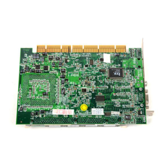
Introduction Welcome to the PSB-810EAV Pentium® III, Celeron Single Board Computer. The PSB-810EAV board is a PCI form factor board, which comes equipped with high performance Pentium® III, Celeron ™ ,VIA Cyrix® ¢ » Processor and advanced high performance multi-mode I/O, designed for the... -
Page 7: Specifications
1.1 Specifications : • CPU : Celeron™ 300 - 550Mhz or above Processor Pentium® III(FC -PGA) 450 - 700Mhz or above Processor VIA Cyrix® ¢ » 466MHz or above • FSB : Support 66/100/133MHz • : PCISA connector with PCI signal only, compatible to Jump PISA Ver. -
Page 8: What You Have
• Operating Temperature : 0 ° ~ 60 ° C ( CPU needs Cooler) 1.2 What You Have In addition to this User's Manual , the PSB-810EAV package includes the following items: • PSB-810EAV Celeron™ , Pentium® III Single Board Computer •... -
Page 9: Installation
Installation This chapter describes how to install the PSB-810EAV. At first, the layout of PSB-810EAV is shown, and the unpacking information that you should be careful is described. jumpers switches setting PSB-810EAV's configuration, such as CPU type selection, system clock setting, and watch dog timer, are also included. -
Page 10: Clear Cmos Setup
Clear CMOS Setup If want to clear the CMOS data (for example you forgot the password, you should clear the CMOS and then set the password again.), you should close the JP7(2-3) about 3 seconds, then open. • JP7 : Clear CMOS Setup DESCRIPTION Keep CMOS Setup (Normal Operation) -
Page 11: System Power On/Off By Keyboard
System Power On by Keyboard when use ATX as Power Supply Use keyboard to turn on the system, if ATX power supply are equipped. • JP8 : Power On by Keyboard DESCRIPTION Disabled Enabled TV OUT Setting Select the format of TV output signal. This function is enabled by graphic driver in Windows OS. -
Page 12: Connection
This chapter describes how to connect peripherals, switches and indicators to the PSB-810EAV board. 3.1 Floppy Disk Drive Connector PSB-810EAV board is equipped with a 34-pin daisy-chain driver connector cable. • CN6 : FDC CONNECTOR 33 31 29 … 5 3 ¡... -
Page 13: Pci E-Ide Disk Drive Connector
GROUND - DEFAULT INTERRUPT IOCS16#-DEFAULT HDC CS0# HDC CS1# HDD ACTIVE# GROUND 3.3 TV Out Connector The PSB-810EAV built-in two TV ports for the future new I/O bus expansion. Artisan Technology Group - Quality Instrumentation ... Guaranteed | (888) 88-SOURCE | www.artisantg.com... -
Page 14: Parallel Port
2. GND 3. Y 4. GND 3.4 Parallel Port This port is usually connected to a printer, The PSB-810EAV includes an on-board parallel port, accessed through a 26-pin flat-cable connector CN1. • CN10 : Parallel Port Connector 13 12 11 … 3 2 1 ¡... -
Page 15: Serial Ports
3.5 Serial Ports The PSB-810EAV offers two high speed NS16C550 compatible UARTs with Read/Receive 16 byte FIFO serial ports. CN5 : COM1 CN12 : COM2 5 4 3 ¡ ¡ ¡ ¡ ¡ ¡ ¡ ¡ ¡ ¡ 10 9 8 •... -
Page 16: Usb Port Connector
• CN25 : 5-pin External Keyboard Connector PIN NO. DESCRIPTION KEYBOARD CLOCK KEYBOARD DATA GROUND 3.7 USB Port Connector The PSB-810EAV built-in two USB ports for the future new I/O bus expansion. CN22 : USB 0(External) CN14 : USB 1(Internal) 1. VCC 2. DATA- 3. DATA+ 4. -
Page 17: Irda Infrared Interface Port
RESERVE GROUND 3.9 IrDA Infrared Interface Port The PSB-810EAV built-in a IrDA port which support Serial Infrared(SIR) or Amplitude Shift Keyed IR(ASKIR) interface. When use the IrDA port have to set SIR or ASKIR model in the BIOS’ s Peripheral Setup’ s COM 2. Then the normal RS -232 COM 2 will be disabled. -
Page 18: Fan Connector
IR-RX Ground IR-TX 3.10 Fan Connector The PSB-810EAV provides CPU cooling fan connector, chassis fan connector. These connectors can supply 12V/500mA to the cooling fan. In the connector there have a “rotati on” pin . The rotation pin is to get the fan’ s rotation signal to system. -
Page 19: Lan Rj45 Connector
3.12 LAN RJ45 Connector PSB-810EAV is equipped with a built-in 10/100Mbps Ethernet Controller. You can connect it to your LAN through RJ45 LAN connector. The pin assignments are as following: • CN16 : LAN RJ45 Connector PIN NO. DESCRIPTION PIN NO. -
Page 20: Lan Led Connector
CN20 : CD IN 1. LEFT SIGNAL 2. GROUND 3. GROUND 4. RIGHT SIGNAL CN8 : MIC IN l l l l 1 2 3 4 1. MIC IN 2. GROUND 3. GROUND 4. REF CN7 : Left/Right Audio Output Connector l l l l 1 2 3 4 1. -
Page 21: Bios Setup
BIOS Setup 4.1 Introduction This chapter discusses the Setup program built into the BIOS. The Setup program allows users to configure the system. This configuration is then stored in battery-backed CMOS RAM so that it retains the Setup information while the power is off. 4.2 Starting Setup The BIOS is immediately active when you turn on the computer. -
Page 22: Using Setup
4.3 Using Setup In general, you can use the arrow keys to highlight items, press <Enter> to select, use the PageUp and PageDown keys to change entries, press <F1> for help and press <Esc> to quit. The following table provides more details about how to navigate in the Setup program using the keyboard. -
Page 23: Main Menu
4.4 Main Menu Once you enter the AwardBIOS™ CMOS Setup Utility, the Main Menu will appear on the screen. The Main Menu allows you to select from several setup functions and two exit choices. Use the arrow keys to select among the items and press <Enter> to accept and enter the sub-menu. - Page 24 4.4.1 Setup Items The main menu includes the following main setup categories. Recall that some systems may not include all entries. Standard CMOS Features Use this menu for basic system configuration. See Section 4.5 for the details. Advanced BIOS Features Use this menu to set the Advanced Features available on your system.
- Page 25 PC Health Status Use this menu to monitor your hardware. Frequency/Voltage Control Use this menu to specify your settings for frequency/voltage control. See section 4.12 for the details. Load Fail-Safe Defaults Use this menu to load the BIOS default values for the minimal/stable performance for your system to operate.
-
Page 26: Standard Cmos Setup
4.5 Standard CMOS Setup The items in Standard CMOS Setup Menu are divided into 10 categories. Each category includes no, one or more than one setup items. Use the arrow keys to highlight the item and then use the <PgUp> or <PgDn> keys to select the value you want in each item. CMOS Setup Utility - Copyright ( C ) 1984-2000 Award Software Standard CMOS Features Date:... - Page 27 Main Menu Selections Item Options Description Date MM DD YYYY Set the system date. Time HH : MM : SS Set the system time Options are in its sub menu Press <Enter> to enter the sub Primary Master (described in Table 3) menu of detailed options Options are in its sub menu Press <Enter>...
- Page 28 IDE Adapters The IDE adapters control the hard disk drive. Use a separate sub menu to configure each hard disk drive. Figure 2 shows the IDE primary master sub menu. CMOS Setup Utility – Copyright © 1984 -2000 Award Software IDE Primary Master IDE HDD Auto-Detection Press Enter...
- Page 29 Use the legend keys to navigate through this menu and exit to the main menu. Use Table 3 to configure the hard disk. Item Options Description IDE HDD Auto- Press Enter Press Enter to auto-detect detection the HDD on this channel. If detection is successful, it fills the remaining fields on this menu.
-
Page 30: Advanced Bios Setup
4.6 dvanced BIOS Features This section allows you to configure your system for basic operation. You have the opportunity to select the system’ s de fault speed, boot- up sequence, keyboard operation, shadowing and security. CMOS Setup Utility – Copyright © 1984 – 2000 Award Software Advanced BIOS Features Virus Warning Disabled... - Page 31 Virus Warning Allows you to choose the VIRUS Warning feature for IDE Hard Disk boot sector protection. If this function is enabled and someone attempt to write data into this area, BIOS will show a warning message on screen and alarm beep. Enabled Activates automatically when the system boots up causing a warning message to appear when anything...
- Page 32 Quick Power On Self Test This category speeds up Power On Self Test (POST) after you power up the computer. If it is set to Enable, BIOS will shorten or skip some check items during POST. Enabled Enable quick POST Disabled Normal POST First/Second/Third/Other Boot Device...
- Page 33 Gate A20 Option Select if chipset or keyboard controller should control GateA20. Normal A pin in the keyboard controller controls GateA20 Fast Lets chipset control GateA20 Typematic Rate Setting Key strokes repeat at a rate determined by the keyboard controller. When enabled, the typematic rate and typematic delay can be selected.
- Page 34 Security Option Select whether the password is required every time the system boots or only when you enter setup. System The system will not boot and access to Setup will be denied if the correct password is not entered at the prompt.
-
Page 35: Advanced Chipset Setup
4.7 Advanced Chipset Features CMOS Setup Utility – Copyright © 1984 – 2000 Award Software Advanced Chipset Features SDRAM CAS Latency Time Item Help SDRAM Cycle Time Tras/Trc _______________________ Ø SDRAM RAS-to-CAS Delay Menu Level SDRAM RAS Precharge Time 3 System BIOS Cacheable Disabled Video BIOS Cacheable... - Page 36 DRAM Settings The first chipset settings deal with CPU access to dynamic random access memory (DRAM). The default timings have been carefully chosen and should only be altered if data is being lost. Such a scenario might well occur if your system had mixed speed DRAM chips installed so that greater delays may be required to preserve the integrity of the data held in the slower memory chips.
- Page 37 System BIOS Cacheable Selecting Enabled allows caching of the system BIOS ROM at F0000h-FFFFFh, resulting in better system performance. However, if any program writes to this memory area, a system error may result. The choice: Enabled, Disabled. Video BIOS Cacheable Select Enabled allows caching of the video BIOS , resulting in better system performance.
- Page 38 On-Chip Video Window Size Select the on-chip video window size for VGA drive use. The Choice: 32MB, 64MB, Disabled. Power-Supply Type This item controls the power-supply type to AT or ATX. The Choice: AT,ATX. Artisan Technology Group - Quality Instrumentation ... Guaranteed | (888) 88-SOURCE | www.artisantg.com...
-
Page 39: Integrated Peripherals
4.8 Integrated Peripherals CMOS Setup Utility – Copyright © 1984 – 2000 Award Software Integrated Peripherals On-Chip Primary PCI IDE Enabled Item Help On-Chip Secondary PCI IDE Enabled ________________ Ø IDE Primary Master PIO Auto Menu Level IDE Primary Slave PIO Auto If your IDE hard IDE Secondary Master PIO... - Page 40 The choice: Auto, Mode 0, Mode 1, Mode 2, Mode 3, Mode 4. IDE Primary/Secondary Master/Slave UDMA Ultra DMA-33/66 implementation is possible only if your IDE hard drive supports it and the operating environment includes a DMA driver (Windows 95 OSR2 or a third-party IDE bus master driver). If your hard drive and your system software both support Ultra DMA-33/66, select Auto to enable BIOS support.
- Page 41 IDE HDD Block Mode Block mode is also called block transfer, multiple commands, or multiple sector read/write. If your IDE hard drive supports block mode (most new drives do), select Enabled for automatic detection of the optimal number of block read/writes per sector the drive can support. The choice: Enabled, Disabled POWER ON Function This POWER On Function allows you to select following items.
- Page 42 Onboard Parallel Port Select an address and corresponding interrupt for the parallel ports. The choice: 378/IRQ7, 278/IRQ5, 3BC/IRQ7, Disabled, Parallel Port Mode Select a parallel operation mode. The choice: SPP, EPP, ECP,ECP+EPP WatchDog Timer Unit Select Select the WatchDog Timer unit. The choice: Second, Minute Artisan Technology Group - Quality Instrumentation ...
-
Page 43: Power Management Setup
4.9 Power Management Setup The Power Management Setup allows you to configure you system to most effectively save energy while operating in a manner consistent with your own style of computer use. CMOS Setup Utility – Copyright © 1984 – 2000 Award Software Power Management Setup ACPI function Disabled... - Page 44 ACPI Suspend Type This item allows you to S1(Power ON Suspend)/S3(Suspend To RAM) the Advanced Configuration and Power Management (ACPI). The choice: S1(POS), S3(STR). Power Management This category allows you to select the type (or degree) of power saving and is directly related to the following modes: 1.
- Page 45 Video Off Method This determines the manner in which the monitor is blanked. V/H SYNC+Blank This selection will cause the system to turn vertical horizontal synchronization ports and write blanks to the video buffer. Blank Screen This option only writes blanks to the video buffer.
- Page 46 HDD Power Down When enabled and after the set time of system inactivity, the hard disk drive will be powered down while all other devices remain active. The choice: 1Min, 2Min, 3Min, 4Min, 5Min, 6Min, 7Min, 8Min, 9Min, 10Min, 11Min, 12Min, 13Min, 14Min, 15Min, Disabled. Soft-Off by PWR-BTN Pressing the power button for more than 4 seconds forces the system to enter the Soft-Off state when the system has “hung.”...
-
Page 47: Pnp/Pci Configuration Setup
4.10 PnP/PCI Configuration Setup This section describes configuring the PCI bus system. PCI, or Personal Computer Interconnect, is a system which allows I/O devices to operate at speeds nearing the speed the CPU itself uses when communicating with its own special components. This section covers some very technical items and it is strongly recommended that only experienced users should make any changes to the default settings. - Page 48 Resource controlled by The Award Plug and Play BIOS has the capacity to automatically configure all of the boot and Plug and Play compatible devices. However, this capability means absolutely nothing unless you are using a Plug and Play operating system such as Windows®95. If you set this field to “manual”...
-
Page 49: Pc Health Status
4.11 PC Health Status CMOS Setup Utility – Copyright © 1984 -2000 Award Software PC Health Status CPU V-Core 1.57V Item Help CPU VTT 1.49V ------------------------- Ø System 3.3V 3.28V Menu Level System 5V 4.99V System 12V 12.35V System -5V (-) 5.11V System -12V (-) 12.23V... -
Page 50: Defaults Menu
Auto Detect DIMM/PCI Clk This item allows you to enable/disable auto detect DIMM/PCI Clock. The choice: Enabled, Disabled. Spread Spectrum This item allows you to enable/disable the spread spectrum modulate. The choice: Enabled, Disabled. CPU Clock Ratio This item allows you to select CPU clock ratio. The choice: 3, 3.5, 4, 4.5, 5, 5.5, 6, 6.5, 7, 7.5, 8. -
Page 51: Supervisor/User Password Setting
4.14 Supervisor/User Password Setting You can set either supervisor or user password, or both of then. The differences between are: supervisor password : can enter and change the options of the setup menus. user password just can only enter but do not have the right to change the options of the setup menus. -
Page 52: Exit Selecting
You determine when the password is required within the BIOS Features Setup Menu and its Security option (see Section 3). If the Security option is set to password will be required both at boot and at entry to Setup. If set to “Setup”, prompting only occurs when trying to enter Setup. - Page 53 Appendix A. WatchDog Timer The WatchDog Timer is provided to ensure that standalone systems can always recover from catastrophic conditions that cause the CPU to crash. This condition may have occurred by external EMI or a software bug. When the CPU stops working correctly, hardware on the board will either perform a hardware reset (cold boot) or a Non-Maskable Interrupt (NMI) to bring the system back to a known state.
- Page 54 Example program: ; INITIAL TIMER PERIOD COUNTER W_LOOP: AX, 6F02H ;setting the time-out value BL, 30 ;time-out value is 48 seconds ; ADD YOUR APPLICATION PROGRAM HERE EXIT_AP, 1 ;is your application over? W_LOOP ;No, restart your application AX, 6F02H ;disable Watchdog Timer BL, 0 ;...
- Page 55 Appendix B. Address Mapping IO Address Map I/O address Range Description 000-01F DMA Controller #1 020-021 Interrupt Controller #1, Master 040-05F 8254 timer 060-06F 8042 (Keyboard Controller) 070-07F Real time Clock, NMI Mask 080-09F DMA Page Register 0A0-0BF Interrupt Controller #2 0C0-0DF DMA Controller #2 Clear Math Coprocessor Busy...
- Page 56 1st MB Memory Address Map Memory address Description 00000-9FFFF System memory A0000-BFFFF VGA buffer C0000-C7FFF VGA BIOS F0000-FFFFF System BIOS 1000000- Extend BIOS *Default setting IRQ Mapping Table IRQ0 System Timer IRQ8 RTC clock IRQ1 Keyboard IRQ9 Available IRQ2 Cascade to IRQ Controller IRQ10 Available IRQ3...
- Page 57 ATX power supply but has two types of power switch connection: 2.1. PSB-810EAV (through Power Button & GND): Connect the ATX power button switch to the pin 17 (power button) and pin 19 (+5VSB) of CN19 on the board. And connect the power cable from CN4 of backplane to CN2 of CPU card.
- Page 58 B. For the backplanes with ATX power supply connector For some SBC without ATX power ON/OFF function, then you can control the ATX power supply through backplane’ s PS ON connector. Refer to the figure below: for the backplanes with ATX connector, the connection can be made simply as following: Connect the ON/OFF (ordinary one) switch to Pin 2 (PS ON) and Pin 3 (GND) of connector CN2...
- Page 59 Artisan Technology Group is your source for quality new and certified-used/pre-owned equipment SERVICE CENTER REPAIRS WE BUY USED EQUIPMENT • FAST SHIPPING AND DELIVERY Experienced engineers and technicians on staff Sell your excess, underutilized, and idle used equipment at our full-service, in-house repair center We also offer credit for buy-backs and trade-ins •...
Need help?
Do you have a question about the PSB-810EAV and is the answer not in the manual?
Questions and answers