Table of Contents
Advertisement
Quick Links
INSTRUCTION
MANUAL
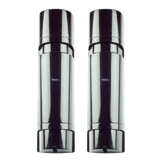
Thank you for purchasing our "intelligent" quad photoelectric beam. This unit will provide long term dependable service when properly
installed. Please read the Instruction Manual carefully for correct and effective use.
Please note:
This sensor is designed to detect intrusion and initiate an alarm; it is not a burglary-preventing device. TAKEX is
not responsible for damage, injury or losses caused by accident, theft, Acts of God (including inductive surge by
lightning), abuse, misuse, abnormal usage, faulty installation of improper maintenance.
FEATURE
The PB-IN-HF series beams are equipped with many features, which provide a wide choice of field selectable options.
These options result in considerable flexibility for a variety of application requirements. The features are;
• Four synchronised beams
4 beams are "and-gated" which helps to prevent false alarms
from flying debris and small animals.
• High power infrared
The active infrared transmission is exceptionally strong with a
maximum arrival distance ten times greater than the specified
protection distance.
• Four frequency selections
4 separate choices of frequency avoids cross-talk in stacked or
long linear installations. Allows stacking of Transmitters or
Receivers all on one side.
• Beam transmission strength selection
2 levels of beam transmission strength, which can be set to suit
the protection distance.
• Auto-gain lock
Optimal sensitivity gain is automatically set at any coverage
distance up to the maximum protection distance. (Audible
tone indicates setting is completed.)
1
PARTS DESCRIPTION
Cover
Horizontal fine
adjustment screw
Vertical
adjustment screw
Terminals
Tamper switch
(Receiver only)
Gain lock switch
(Receiver only)
Functions indications
as below
[Transmitter]
Beam channel
(frequency 1-4)
(1ch. set at factory)
Operation LED
PHOTOELECTRIC BEAM SENSOR [INTELLIGENT]
PB-IN-50HF
OUTDOOR 165' (50m) INDOOR 330' (100m)
PB-IN-100HF OUTDOOR 330' (100m) INDOOR 660' (200m)
PB-IN-200HF OUTDOOR 660' (200m) INDOOR 1320' (400m)
View finder
Mirror
Mirror
Adjustment dial
Functions / Indications
[Receiver]
Sensitivity attenuation LED
Response time adjustment
(50msec. set at factory)
• Environmental module
Environmental trouble signal is sent when beam reception level is
reduced below an acceptable level.
• Programmed AGC function
Sensitivity is automatically increased in bad weather to contend
with fog, rain, or frost.
• Alarm memory indicator
Alarm memory LED located on Receiver can be manually reset
(at sensor) or remotely controlled via panel.
• Audible signal for alignment
An alignment tone aids in quick set-up of beams for electrical
measurement of alignment.
• Other features
Monitor output, Response time changeover, Tamper output.
Mounting plate
Bracket
Shading plate
Alarm LED
1.
SOLD SEPARATELY
Knockout
Pole cover
Accessory
Tapping screw
(ø4x30) : 8
Oval countersunk
head screw
(ø4x20) : 8
Knockout
Monitor jack
Beam channel (frequency 1-4)
(1ch. set at factory)
Environmental output terminal
Advertisement
Table of Contents

Summary of Contents for Takex PB-IN-50HF
- Page 1 Please read the Instruction Manual carefully for correct and effective use. Please note: This sensor is designed to detect intrusion and initiate an alarm; it is not a burglary-preventing device. TAKEX is not responsible for damage, injury or losses caused by accident, theft, Acts of God (including inductive surge by lightning), abuse, misuse, abnormal usage, faulty installation of improper maintenance.
- Page 2 CAUTIONS Position the sensor with consideration to installation site, installation height and protection distance for effective use. 1) DON'T'S 2) Installation height and protection distance 95mm 134mm Avoid strong light from sun, automobile headlights etc. • Do not install in a site where shining on transmitter or 95mm receiver (Avoid light in a...
- Page 3 6. Wiring Distance between sensor and control panel. Note PB-IN-50HF PB-IN-100HF PB-IN-200HF • Max. wiring distance Wire Size Dia. when two or more sets AWG22 0.65 394' (120m) 3610' (1100m) 361' (110m) 3281' (1000m) 328' (100m) 2953' ( 900m) are connected is the above value divided by AWG20 0.80...
- Page 4 • Attach U brackets to pole and secure to mounting plate with screws. • Attach sensor body. • Pull through wire. • Connect terminals. • Attach covers. (Break knockouts on cover and *pole cover to adapt to pole diameter and configuration.) *SOLD SEPARATELY U bracket Knockout...
- Page 5 SET-UP OF FUNCTIONS AND BEAM ALIGNMENT 1) Supply power with cover detached. 2) Set function options. (Refer to 7. FUNCTIONS DESCRIPTION for detailed explanation of each option.) Location Functions Function Switches Voltmeter Beam channel 1 ch. 2 ch. 3 ch. (10V DC) TR / RE (frequency)
- Page 6 FUNCTIONS DESCRIPTION 1. Four channel frequency selection The beam pairs may be set at various frequency levels to 1) Linear protection avoid crosstalk between units which are stacked, in-line, or other configurations which have the potential of spill-over transmission from one beam to another. Set the frequency level as illustrated.
- Page 7 2) A "beep" tone is issued from the receiver approximately 5 seconds after the cover is put into position. This tone indicates the Auto-gain has been set. Refer to the chart below. Tone Indicates Result Cause Remedy One pulse Optimal sensitivity has (Beep) been set.
- Page 8 3. Remove reflecting object. Set beam power to beam is broken sent into the receiver Low. Contact TAKEX for further remedies 4. Four beams are not broken simultaneously 4. Ensure all beams are broken at same time 5. Beam interruption time is shorter than response time 5.


Need help?
Do you have a question about the PB-IN-50HF and is the answer not in the manual?
Questions and answers