Advertisement
Quick Links
We appreciate your purchase of a TAKEX passive infrared sensor. This sensor will provide long and dependable service when properly
installed. Please read this Instruction Manual carefully for correct and effective use.
Please Note: This sensor is designed to detect intrusion and to initiate an alarm ; it is not a burglary-preventing device.
TAKEX is not responsible for damage, injury or losses caused by accident, theft, Acts of God ( including inductive
surge by lightning ), abuse, misuse, abnormal usage, faulty installation or improper maintenance.
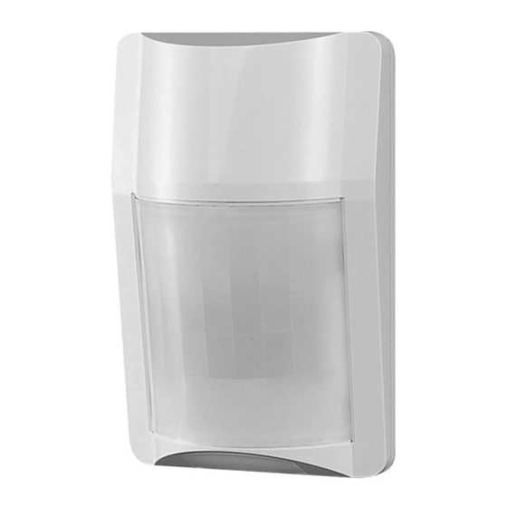
Cove r
Lens
Cover lock screw /
•Install the sensor in a location such that intruders are more likely
to cross the protection zones, rather than approach head on.
•Do not install in a site which is subject to electrical noise or intense
vibration.
•Avoid direct sunlight, spot light or intense reflections on the sensor
or the protection zone.
•Do not install the sensor outdoors (indoor use only).
•Do not install the sensor directly on the ceiling. (When installed on
ceiling, use optional attachment BCW-401.)
TAKEX
Wide angle protection : PIR-T45WP (40 lbs PET IMMUNE)
1. PARTS DESCRIPTION
,,
---
2. DO'S AND DON'T'S
3. COVERAGE RANGE AND PET IMMUNITY
■
Wide Angle PIR-T45WP
Base
Wiring hole
(Knockout)
Lock screw
Index
Mounting hole
(Knockout)
The area of protection can be adjusted to allow
for different mounting heights as below side view.
Loosen Lock Screw, and by moving the inner
PCB upwards, the coverage of the sensor can be
shortened.
There are three field coverage index marks that
are printed onto th � P <? B located Matched to the
on the left hand side 1ust below
the left PCB guide rail. They are
to be matched to the bottom of
the guide rail. If the PCB is raised
past the bottom index the tamper
plunger will not activate, leaving
the circuit open; in alarm.
eThe sensor is designed to not detect animals
under 40lbs. (20kg).
eTo maintain maximum pet immunity, the sensor
is required to be installed 8.2ft (2.5m) from the
floor vertically without changing the set up as it
comes.
eThe sensor may detect multiple animals in the
protection area even that are smaller than
401bs.
eArea adjustment by PCB will decrease the pet
immunity.
e11 is therefore recommended
to use optional BCW-401 multi
purpose mounting bracket if
area adjustment is required,
which
will
minimize
performance deterioration of
the pet immunity.
PASSIVE INFRARED SENSOR
Instruction Manual
PROTECTION AREA ADJUSTMENT
PET IMMUNITY
Terminals
Tamper switch
Alarm LED
(Red)
Mode selector
Recessed
Wiring hole
•The passive infrared sensor is designed to detect infrared energy variations
caused by the presence of a human body. Therefore, note that similar
variations in conditions in protection area, due to other reasons, may cause
the sensor to create an alarm as it is unable to distinguish between sources.
[MAINTENANCE]
•When the unit is soiled, clean the cover with a soft cloth moistened with a
small amount of cleansing -solution. Do not use chemicals such as thinners
or alcohol.
•Check operation once a week. Do not fail to check operation
furniture in coverage area is moved.
non - polarity N.C./N.O.
ege
;t
�\ \
�
�
Indexes
Allowable wiring distance between sensor ]
and power source
Size of wire used
AWG 22 (Dia. 0.65mm)
AWG 20 (Dia. 0.80mm)
AWG 18 (Dia. 1.00mm)
•The maximum wire length, when two or more units
are connected, is the above distance divided by the
number of units.
•The protection circuit can be wired to a distance of
3,300 ft (1,000m) with AWG 22 (0.65mm dia.) wire.
•All wiring should be in accordance with the national
electric code NFPA-70.
•The power supply used with this unit must have a
minimum 4 hours standby power capability.
�
the
ir
c«>
E�
:, a,
� :!
4. WIRING
POWER ALARM
10-18VDC 24V/0.25A
25mA
1 k k1 k k1
I
"l
Distance at 12VDC
830 ft. (250m)
1470 ft. (450m)
2300 ft. (700m)
�
TAMPER
30VDC/0.1A
(AC/DC)
Corner
Mounting
Hole
whenever
N.C.
Advertisement

Related Manuals for Takex PIR-T45WP


Summary of Contents for Takex PIR-T45WP
- Page 1 We appreciate your purchase of a TAKEX passive infrared sensor. This sensor will provide long and dependable service when properly installed. Please read this Instruction Manual carefully for correct and effective use. Please Note: This sensor is designed to detect intrusion and to initiate an alarm ; it is not a burglary-preventing device.
- Page 2 , faul , improp epairs thos provid d by e or nten r an TAKEX. All impli d warra s wi o TAKEX, i cludi g impli d warra s for merchant bility nd impli d warr...
Need help?
Do you have a question about the PIR-T45WP and is the answer not in the manual?
Questions and answers