Advertisement
Quick Links
Advertisement

Related Manuals for H-KING NIEUPORT 28


Summary of Contents for H-KING NIEUPORT 28
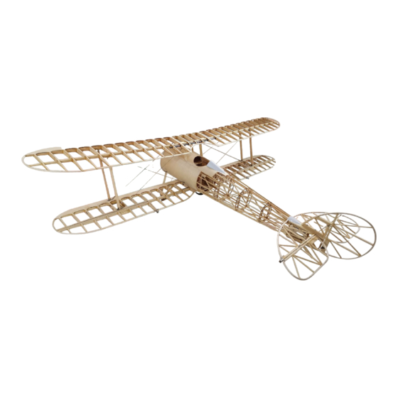
- Page 1 1:3 SCALE 2830MM NIEUPORT 28 laser cut balsa kit BUILDING INSTRUCTION...
-
Page 2: Safety Precautions
• This is a radio controlled flying model and as such must always be flown with caution and care. This is not a toy. • The NIEUPORT 28 is designed for intermediate to advanced pilots. • Alway exercise great caution when using the recommended battery to power this product. For full safety notes and operating procedures, please see information provided by your battery supplier. - Page 3 NIEUPORT 28 Features: • 1/3 Scale detail and scheme-based on NIEUPORT 28c-1. • Extremely lightweight, state-of-the-art all-wood construction • Fiberglass cowl • Complete Hardware Pack. • Stainless Steel Flying Wires and Terminations. • Sprung and Damped Telescopic Undercarriage. • Full-scale simulation metallic structure.
-
Page 4: Fuselage Assembly
NIEUPORT 28 A. Fuselage Assembly. 1. Laminate together the 2 parts to make the motor firewall and the 2 components that form the curved top as shown. 2. Follow the next steps to assemble the 2 wing support sections. Please ensure you build a left-hand and a right-hand side. - Page 5 NIEUPORT 28 3. Assemble over the plan the rear fuselage sections, you need to make 2 of these, one for each side. Then follow the next sequence of pictures to join the wing support section to the rear fuselage section. Once again remember, you must join them together to make a left-hand and a right-hand side.
- Page 6 NIEUPORT 28 4. Glue the motor firewall to the front of the the 2 fuselage sides. Do this over the plan and be very careful that the firewall stays square to sides and the assembly stays level as the glue dries.
- Page 7 NIEUPORT 28 6. Position the fuselage frame over the plan and make sure the assembly stays square and level. Cut from the supplied stripwood a cross brace and insert at the rear and base of the wing support section. Use clamps as shown to hold the parts together as the glue dries.
- Page 8 NIEUPORT 28...
- Page 9 NIEUPORT 28 8. Add the firewall stiffener plate which is reinforced with triangular shaped strips. 9. Trim the triangular shaped strip and glue to the rear of A19 as shown.
- Page 10 NIEUPORT 28 10. Glue into place the rear fuselage cross brace. Then using one of the supplied stringers cut it according to the plan and glue to the rear of the fuselage as shown. Add the triangular reinforcing strips to the corners of the rear cross brace and the fuselage sides.
- Page 11 NIEUPORT 28 12. Trim to fit the 10x28x270mm stringers as shown. Glue to plywood parts A4-A5, when these are dry cut of the excess from the stringers. 13. Use a hobby saw to cut the 6x8mm stringer as shown. Install a 10x28x27mm pine strip to this area as shown on the plan, trim off the...
- Page 12 NIEUPORT 28 14. At this point glue into place all the rounded formers to the bottom of the fuselage. When these are dry add the stringers as shown.
- Page 13 NIEUPORT 28 15. Identify the parts for the rear servo mount and assemble as shown. When assembled glue into position. 16. Identify the parts for the front servo and equipment mounts and assemble as shown. When assembled glue them into position in the...
- Page 14 NIEUPORT 28 17. Wing struts: Drill 3mm and 12mm holes into the struts as shown, refer to the plan for the exact positions. Sand the struts to the oval streamlined profiles shown. 18. Lay the struts onto the plan and mark their mounting position.
- Page 15 NIEUPORT 28 19. Remove the part of the stringer that is stopping the struts being positioned in the fuselage. Carefully check the alignment of the struts before glueing into place.
- Page 16 NIEUPORT 28 20. Use the thin plywood sheets to form the top of the fuselage, hold with masking tape as the glue dries. 21. Install the metal fittings ready for the rigging wires etc.
- Page 17 NIEUPORT 28 22. Use the thin plywood sheets to form the sides of the fuselage, hold with masking tape and pins as the glue dries. Slot the ply to allow the metal fittings to pass through. 23. Identify the pinewood parts for the landing gear and assemble according to the drawing on the plan.
- Page 18 NIEUPORT 28 24. Identify the pinewood parts for the landing gear and assemble according to the drawing on the plan. 25. Landing gear assembly.
- Page 19 NIEUPORT 28 26. Use the thin plywood sheets to form the bottom of the fuselage, hold with masking tape as the glue dries. 27. Using wing rib A17 as a template, draw a line around it onto the fuselage plywood turtle deck as shown. Next, cut the plywood to the...
- Page 20 NIEUPORT 28 28. Make a hole in the plywood turtle deck for the servo lead in the position shown. 29. Glue the wing rib to the struts as shown. When dry plank the openings/gaps with plywood sheet then sand to shape.
- Page 21 NIEUPORT 28 30. Drill holes in the plywood covering for the landing gear screws. 31. Assemble the landing gear to the fuselage using the metal parts provided and install the diagonal wire bracing.
- Page 22 NIEUPORT 28 32. Glue the tail skid mount to the rear of the fuselage.
- Page 23 NIEUPORT 28 33. Identify the parts for the tail skid and assemble as shown. When built fit to the rear of the fuselage. 34 Plank the rear of the fuselage as shown and when dry cut a slot for the pushrod to exit.
- Page 24 NIEUPORT 28 35. Installation of the center wing section. Instructions for building 36. Make the wing struts to the profiles shown on the plan. Drill the center section are shown near the end of the manual. holes in the positions shown and sand to shape.
-
Page 25: Wing Assembly
NIEUPORT 28 38. Contruct the windshield and rear cockpit fairing using the parts supplied as shown. Install now or after covering. B. Wing Assembly. 1. Assemble the upper wings over the plan using the wing ribs, wing spars, leading edge and trailing edge strips. Ensure that you make a left... - Page 26 NIEUPORT 28 2. Trim the leading edge and trailing edge at the wing tip end to allow for a good glue joint of the wing tip itself. Glue the curved wing tip to the leading edge, trailing edge and spars.
- Page 27 NIEUPORT 28 4. Assemble the lower wings once again over the drawing as per the upper wings in steps 1 to 2. Once again ensure that you make a left and right wing panel. 5. Sand the wooden reinforcement blocks to fit into the position shown in the lower wings, when satisfied with the fit, glue into place.
- Page 28 NIEUPORT 28 6. Sheet the leading edge of both wing panels with plywood as shown. Pin and clamp into position as the glue dries. 7. Glue to both left and right wing panels the pinewood strips to form the trailing edge as shown.
- Page 29 NIEUPORT 28 8. Glue the supplied 1mm balsa strips to the wing ribs as shown and sand to shape. At this point also add the wing servo mounts, refer to the plan for the positions. 9. Assemble a left and right-hand aileron over the plan using the parts supplied.
- Page 30 NIEUPORT 28 10. Assemble a left and right-hand aileron over the plan using the parts supplied. 11. Drill holes and install the ailerons using the supplied pin hinges as shown. Ensure each aileron surface moves freely up and down and...
-
Page 31: Tail Assembly
NIEUPORT 28 C. Tail Assembly. 1. Before you start to build the horizontal stabilizer assemblies you will need to soak the balsa strips in water before bending to the shape shown on the plan. We recommend that you cover this part of the plan using clear food wrapping film and scotch tape before pinning the balsa down in the required shape as it dries out, this will keep the plan clean and dry. - Page 32 NIEUPORT 28 2. Drill holes in the positions shown to install the supplied pin hinges. 3. Mark the positions of the holes to be drilled in 4. Use a 3mm drill to drill the 2 holes. 5. Install two blind nuts and glue into position the rudder base block as shown on the plan.
- Page 33 NIEUPORT 28 6. Build the rudder and fin assemblies over the plan. 7. Follow the instructions in steps 1 and 2 above for building the rudder and fin, soak the balsa strip and cover the plan in clear film etc.
- Page 34 NIEUPORT 28 8. Trial fit the horizontal stabilizer to the fuselage to the position shown on the plan. Sand as necessary to achieve a good fit and to ensure it is square and level to the fuselage. Once satisfied with the fit, glue into place using a good slow setting epoxy, ensure it remains square and level as the glue sets.
- Page 35 NIEUPORT 28 10. Make the tail flying wires to the different lengths shown on the plan. Install the metal fittings to the fin, fuselage and horizontal stabilizer. Then attach the flying wires to the metal fittings as shown on the plan.
- Page 36 NIEUPORT 28 D. Wing Center Section Assembly. 1. Before you start to build the center section, as 2. Once the balsa strip is dry, assemble the 3. Assemble the wing ribs to the spar to form before, you will need to soak the balsa strips structure in the sequence shown.
- Page 37 NIEUPORT 28 4. Trial fit then glue the trailing edge into place. 6. Glue the 6x8mm Paulownia strips to the front spar. Drill two 3mm holes in the spar in the Use a mediun CA glue and ensure it is pinned positions shown on the plan.
- Page 38 NIEUPORT 28 7. Glue into place the leading edge plywood sheeting, use pins and clamps to hold in position as the glue dries. Give all the assemblies a final sanding before covering with a film or fabric of your choice.
- Page 39 NIEUPORT 28 1/3 Scale Nieuport 28 part list. List of 1/3 Scale Nieport28 Parts item spec item spec Wood sticks Wood sticks NW-01 12X25X1250 NW-23 8X6MM girder NW-02 12X20X1250 NW-24 8X8MM NW-03 12X35X420 NW-25 pine 10X10MM wing brace rod NW-04...
- Page 40 NIEUPORT 28 Pictures for accessories of 1/3 Niueport 28 PIC. PIC. NA-01-02 NA-11 NA-03-04 NA-12 NA-05 NA-13 NA-06 NA-14-15 NA-07-09 NA-16 NA-10 NA-17 NA-18...
Need help?
Do you have a question about the NIEUPORT 28 and is the answer not in the manual?
Questions and answers