
Related Manuals for ADLINK Technology AMP-304C


Summary of Contents for ADLINK Technology AMP-304C
- Page 1 AMP-304C 4-Axis Pulse Motion Controller User’s Manual Manual Rev.: Revision Date: Nov. 4, 2021 Part No: 50M-00053-1000...
- Page 2 Revision History Revision Release Date Description of Change(s) 2021-11-04 Initial release Revision History...
-
Page 3: Preface
AMP-304C Preface Copyright © 2021 ADLINK Technology Inc. This document contains proprietary information protected by copy- right. All rights are reserved. No part of this manual may be repro- duced by any mechanical, electronic, or other means in any form without prior written permission of the manufacturer. - Page 4 California Proposition 65 Warning WARNING: This product can expose you to chemicals including acrylamide, arsenic, benzene, cadmium, Tris(1,3-dichloro-2-propyl) phosphate (TDCPP), 1,4- Dioxane, formaldehyde, lead, DEHP, styrene, DINP, BBP, PVC, and vinyl materials, which are known to the State of California to cause cancer, and acrylamide, benzene, cadmium, lead, mercury, phthalates, toluene, DEHP, DIDP, DnHP, DBP, BBP, PVC, and vinyl materials, which are known to the State of California to cause...
-
Page 5: Table Of Contents
AMP-304C Table of Contents Revision History..............ii Preface ..................iii List of Tables................. vii List of Figures ................ ix 1 Introduction ................ 1 Overview................1 Features................2 1.2.1 General Features ............2 1.2.2 Motion Features ............3 Specifications............... 4 Supported Software ............. 6 1.4.1... - Page 6 Connector Pin Assignments..........19 2.6.1 CN1 – Extended TTL DIO ........... 19 2.6.2 CN2 – AMP-304C Main Connector ......20 2.6.3 CN4 – Encoder Feedback, LTC, and CMP Signals ..23 2.6.4 CN5 – Manual Pulser Input Signals ......25 3 Signal Connections ............
-
Page 7: List Of Tables
CN3 – CMP Output Voltage Selection...... 18 Table 2-6: CN3 Extended TTL DIO ........... 19 Table 2-7: CN2 AMP-304C Main Connector ......20 Table 2-8: CN4 Encoder Feedback, LTC, and CMP Signals..23 Table 2-9: CN5 Manual Pulser Input Signals......25 Table 3-1: Pulse Output Signals .......... - Page 8 This page intentionally left blank. viii List of Tables...
-
Page 9: List Of Figures
AMP-304C List of Figures Figure 1-1: Functional Diagram............1 Figure 2-1: AMP-304C Board Layout..........10 List of Figures... - Page 10 This page intentionally left blank. List of Figures...
-
Page 11: Introduction
AMP-304C Introduction 1.1 Overview AMP-304C is an advanced 4-axis motion controller card with a PCI Express® interface that can generate a pulse train up to 9.99MHz to control a motor. With more general purpose as well as dedicated IOs, functional logic selection switches, 4-channel encoder feedback input, AMP-304C can be used for a multitude of scenarios or applications. -
Page 12: Features
1.2 Features The following lists summarize the main features of the AMP-304C motion control system. 1.2.1 General Features 4-axis pulse type motion card PCI Express® Gen1 x1 Supports up to 16 cards in one system Pulse output frequency up to 9.99 Mpps... -
Page 13: Motion Features
AMP-304C 1.2.2 Motion Features T-Curve and S-Curve: configurable asymmetric profile 13 home return modes Speed and position change on-the-fly Linear / Circular / Helical interpolation Motion stop method selection: EMG / deceleration Backlash compensator / vibration suppression High speed position latch function with configurable filter... -
Page 14: Specifications
1.3 Specifications Pulse Type Motion Control Max. Axes Pulse Output Frequency up to 9.99 Mpps Pulse Output Mode CW/CCW, OUT/DIR, AB Phase Pulse Output Type Differential / Single-End Encoder Feedback Input Mode CW/CCW; 1x/2x/4x AB Phase Encoder Feedback Input Frequency 4 MHz (up to 16 MHz at 4x AB) Positon/Encoder Counter Resolution 32-bit... - Page 15 AMP-304C Other I/O Interface Signals Pulsar Input 1-ch Position Latch Input (Dedicated) 4-ch LTC (up to 1MHz) Position Comparison Trigger Output 4-ch CMP (up to 1MHz) (Dedicated) CMP Output Voltage Selection 5, 24 V or Open Collector 4-ch Optically Isolated DI (up to 10KHz)
-
Page 16: Supported Software
APS Function Library Support 1.4.2 APS Functions The AMP-304C is fully compliant with the APS (Automation Prod- uct Software) function library, independent of programming lan- guages and operating systems (OS). A complete detailed listing of functions can be found in the APS Function Library User Manual. -
Page 17: Accessories
AMP-304C 1.5 Accessories ADLINK’s exclusive DIN-304C terminal board is designed for all AMP-304C signals and functions using ACL-10569, ACL-10437 and ACL-10137 cables. Another way to connect is with ADLINK’s DIN-68S terminal board and ACL-10569 cable. For extended connectors, Encoder Feed- back, LTC, and CMP as well as TTL DIO, use a DIN-37 terminal board with ACL-10437 and ACL-10137 cables (sold separately). - Page 18 This page intentionally left blank. Introduction...
-
Page 19: Getting Started
This chapter describes how to install and connect to the AMP- 304C, its hardware settings, and related signals. 2.1 Package Contents The package includes the following items: 1x AMP-304C Card 4-Axis Pulse Motion Controller 1x ACL-10437 (DB37F - IDC40) Cable 4x Mini Jumper (2P) Product Warranty Card If any of these items are missing or damaged, contact the dealer from whom you purchased the product. -
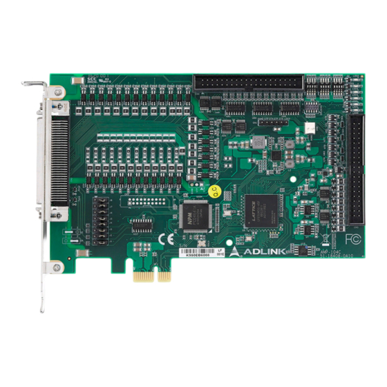
Page 20: Board Layout
2.2 Board Layout Figure 2-1: AMP-304C Board Layout Item Description Card ID Selection Switch End Limit Type Selection Switch DO Initial State Selection Switch J1-J8 Pulse Output Mode Selection Jumper Extended TTL DIO 40-pin box header AMP-304C Main Connector 68-pin SCSI... -
Page 21: Hardware And Software Driver Installation
2.3 Hardware and Software Driver Installation 2.3.1 Hardware Configuration The AMP-304C is fully Plug-and-Play compliant and can be installed in any PCI Express slot. It employs a PCI Express Gen1 x1 bus, and the system BIOS can auto-configure memory and IRQ channels. -
Page 22: Troubleshooting
2.3.3 Troubleshooting If the computer cannot power on normally or the motion control system operates abnormally after system installation, follow the steps described below for troubleshooting. If the problem persists, consult your dealer for technical services. Problem Correction The card does not appear in Ensure the card is properly mounted in Windows Device Manager after its the PCI Express slot and the driver is... -
Page 23: Software Driver Installation
1. Download the APS SDK file from ADLINK and run it. Installation executes automatically. 2. Select NEXT as prompted to complete installation. 3. After installation is complete, select FINISH. 4. Ensure the Windows Device Manager lists the AMP-304C. 5. Restart the computer. Getting Started... -
Page 24: Dip Switch Settings
2.4 DIP Switch Settings 2.4.1 SW1 – Card ID Selection The SW1 switch is used to set the card ID. For example, if SW1 Pin 1 is set to ON and the others are OFF, the card index is 1. The index value can be from 0 to 15. -
Page 25: Sw2 - End Limit Type Selection
AMP-304C 2.4.2 SW2 – End Limit Type Selection The SW2 switch is used to set the type of end limit logic, which are Normally Open (NO) and Normally Closed (NC). For example, if the switch pin is set to “OFF”, the type of end limit logic is Normally Open. -
Page 26: Sw3 - Do Initial State Selection
2.4.3 SW3 – DO Initial State Selection The SW3 switch is used to set the initial DO state group setting. For example, if the SW3 Pin1 is set to “OFF”, the initial states of “DO0 to DO3” are Inactive. DO # SW3 Pin No. -
Page 27: Jumper Setting: Pulse Output Mode Selection
AMP-304C 2.5 Jumper Setting: Pulse Output Mode Selection 2.5.1 J1-J8 – Pulse Output Mode Selection Jumpers J1-J8 are used to set the mode of pulse output signals. The output signal mode can either be differential line driver or sin- gle-ended output. Refer to Section 3.1 for detailed jumper set- tings. -
Page 28: Cn3 - Cmp Output Voltage Selection
2.5.2 CN3 – CMP Output Voltage Selection The CN3 jumper is used to set the CMP output (dedicated) volt- age, which are Open Collector Output (default), VDD (5V) and E24V. CMP # Open Collector (Default) VDD (5V) E24V Close Breaks Between 1 and 2 2 and 3 4 and 5... -
Page 29: Connector Pin Assignments
AMP-304C 2.6 Connector Pin Assignments 2.6.1 CN1 – Extended TTL DIO Name Function Name Function TDI0/ TDI1/ 3.3V/5V TTL Input 3.3V/5V TTL Input T-LTC0 T-LTC1 TDI2/ TDI3/ 3.3V/5V TTL Input 3.3V/5V TTL Input T-LTC2 T-LTC3 TDI4 3.3V/5V TTL Input TDI5 3.3V/5V TTL Input... -
Page 30: Cn2 - Amp-304C Main Connector
ALM3 Servo Alarm Signal SVON0 Servo On Signal ALM1 Servo Alarm Signal /DO8 / Digital Output Position Comparison CMP4 SVON1 Servo On Signal Trigger /DO0 /DO9 / Digital Output / Digital Output Table 2-7: CN2 AMP-304C Main Connector Getting Started... - Page 31 / Digital Input Emergency Stop EMG2 RDY3 Servo Ready Signal Signal /DI2 /DI11 / Digital Input / Digital Input Servo In-Position EMG3 Emergency Stop INP0 Signal /DI3 / Digital Input /DI12 / Digital Input Table 2-7: CN2 AMP-304C Main Connector Getting Started...
- Page 32 PEL3 Signal Signal Negative End Limit Negative End Limit MEL1 MEL3 Signal Signal Origin Position Origin Position ORG1 ORG3 Signal Signal External +24V EGND -- External Power GND 68 E24V Power Input Table 2-7: CN2 AMP-304C Main Connector Getting Started...
-
Page 33: Cn4 - Encoder Feedback, Ltc, And Cmp Signals
AMP-304C DGND, used for OUT+/- and DIR+/- signals. EGND, used for others IO signals. DO0-7, configured as CMP Output if not used. NOTE: NOTE: DI0-3, configured as EMG Input if not used. DI4-7, configured as Multi-function if not used. SD: Direction Ramping-down Point Detection Signal. - Page 34 Name Function Name Function External Power EGND O +5V Power Output EZ3- Encoder Z-phase- EZ3+ Encoder Z-phase+ Encoder B- EB3- Encoder B-phase- EB3+ phase+ Encoder A- EA3- Encoder A-phase- EA3+ phase+ EZ2- Encoder Z-phase- EZ2+ Encoder Z-phase+ Encoder B- EB2- Encoder B-phase- EB2+ phase+...
-
Page 35: Cn5 - Manual Pulser Input Signals
AMP-304C 2.6.4 CN5 – Manual Pulser Input Signals Name Function +5V Power Output Pulser A-phase+ Input Pulser A-phase- Input Pulser B-phase+ Input Pulser B-phase- Input EGND External Power GND Table 2-9: CN5 Manual Pulser Input Signals VDD: Generated from E24V in CN2. - Page 36 This page intentionally left blank. Getting Started...
-
Page 37: Signal Connections
Signal Connections Signal connections of all I/O’s are described in this chapter. Refer to the contents of this chapter before wiring any cables between the AMP-304C and any motor drivers. This chapter contains the following sections: Section 3.1: Pulse Output Signals Section 3.2: Encoder Feedback Input Signal... -
Page 38: Pulse Output Signals
3.1 Pulse Output Signals There are 4 axis pulse output signals on the AMP-304C, each supporting up to 9.99 MHz output frequency. For each axis, two pairs of OUT and DIR signals are used to transmit the pulse train and to indicate the direction. In this section, the electrical charac- teristics of the OUT and DIR signals are detailed. - Page 39 AMP-304C The output of the signals can be configured by jumpers as either Single-Ended or Differential Line Driver output. Users can select the output mode either by closing breaks between 1 and 2, or 2 and 3 of jumpers J1-J8 as follows:...
-
Page 40: Encoder Feedback Input Signal
3.2 Encoder Feedback Input Signal The AMP-304C provides 4 encoder feedback input channels each with up to 4MHz and EA, EB, and EZ signals. Each group of EA, EB, and EZ signals contains a pair of differential signals (e.g. the EA signal contains EA+ and EA-). -
Page 41: Motion I/O Interface Signal
3.3 Motion I/O Interface Signal 3.3.1 Emergency Stop Input (EMG) The AMP-304C provides an EMG signal, common with DI. If one of the EMG signals is triggered, all motion control commands will be stopped immediately. Another way to stop operation of each motor immediately is by transmitting an external EMG signal via the DIN-304C to a servo or stepper motor driver. - Page 42 3.3.2.1 Origin Position Signal (ORG) The AMP-304C provides one original or home signal for each axis. This signal is used for defining the zero position of this axis. The logic of this signal must be set properly before performing the home procedure.
- Page 43 These two signals are for safety, which can prevent a machine from crashing when missing an operation. The AMP-304C provides two direction end limit signals, PEL and MEL, for each axis. PEL indicates the end limit signal is in the pos- itive direction and MEL indicates the end limit signal is in the nega- tive direction.
- Page 44 3.3.2.3 Direction Ramping-down Point Detection Signal (SD) The AMP-304C provides one slow-down function through SD sig- nal input for each axis. SD indicates both positive and negative directions. For more information and settings, see the APS Func- tion Library User’s Manual.
-
Page 45: Servo Interface Io
Servo Interface IO 3.3.3.1 Servo-ON Output Signal (SVON) The AMP-304C provides one servo on output signal, SVON, to enable servo drivers for each axis. For more information and set- tings, see the APS Function Library User’s Manual. SVON output signals can be configured as General-Purpose Digi- tal Output signals if not used. - Page 46 Servo Deviation Counter Clear Output Signal (ERC) The AMP-304C provides one deviation counter clear function through ERC for each axis, which can be a pulse or a LEVEL sig- nal output. The output logic and pulse width can be changed using software.
- Page 47 3.3.3.3 Servo Alarm Input Signal (ALM) The AMP-304C provides one servo alarm input signal, ALM, for each axis. The alarm signal is sent by servo drivers. If the ALM signal is triggered, motion of an axis stops immediately, or will decelerate and stop.
- Page 48 3.3.3.4 Servo Ready Input Signal (RDY) The AMP-304C provides one servo ready input signal, RDY, for each axis, which is used to receive the ready signal from a servo driver. If RDY is enabled, the servo driver is ready to receive the pulse command from the AMP-304C.
- Page 49 3.3.3.5 Servo In-Position Input Signal (INP) The AMP-304C provides one in-position input signal, INP, for each axis. It is used to check the position complete signal, which is from the servo driver if the position mode is set. The input logic can be changed using software.
-
Page 50: Gpio Interface Signal
3.4 GPIO Interface Signal The AMP-304C provides a 32-channel onboard optically isolated GPIO (DI/DO) and a 32-channel extended TTL GPIO (TDI/TDO). 16-ch Optically Isolated DI GPIO Onboard Main Connector CN2 16-ch Optically Isolated DO 16-ch Non-isolated TTL DI GPIO Extended... - Page 51 AMP-304C Optically Isolated Digital Input: D3.3V Schmitt E24V FPGA Trigger 3.3K Connector Optically Isolated Digital Output: Connector Digital FPGA Isolator EGND Signal Connections...
-
Page 52: 32-Channel Extended Ttl Gpio (Tdi/Tdo)
3.4.2 32-Channel Extended TTL GPIO (TDI/TDO) CN1 Pin No. Signal Name CN1 Pin No. Signal Name TDI0 TDO0 TDI1 TDO1 TDI2 TDO2 TDI3 TDO3 TDI4 TDO4 TDI5 TDO5 TDI6 TDO6 TDI7 TDO7 TDI8 TDO8 TDI9 TDO9 TDI10 TDO10 TDI11 TDO11 TDI12 TDO12 TDI13... -
Page 53: Other I/O Interface Signals
Any 12-channel position latch input can be assigned to a latch source to trigger any axis by software. The AMP-304C provides 256 position latch buffer points for each axis. For more information, see the APS Function Library User’s Manual. -
Page 54: Position Comparison Trigger Output (Cmp)
3.5.2 Position Comparison Trigger Output (CMP) The AMP-304C provides 16-channel position comparison trigger outputs. CMP 0-3: 4-channal dedicated and isolated output, up to 1MHz CMP 4-11: 8-channel isolated, common with DO, up to 1MHz T-CMP 0-3: 4-channel TTL, common with TDO, up to 1MHz Voltage output selection is controlled by jumper in dedicated CMP outputs;... -
Page 55: Manual Pulser Input Signal (Pa/Pb)
EGND 3.5.3 Manual Pulser Input Signal (PA/PB) The AMP-304C provides one set of manual pusler functions through PA/PB for all axes. CW/CCW and 1x/2x/4x AB Phase modes are supported for receiving external drive pulses. For more information, see the APS Function Library User’s Manual. -
Page 56: Multi-Function Input Signals (Di/Sd/S-Ltc/Pcs/Clr)
3.5.4 Multi-function Input Signals (DI/SD/S-LTC/PCS/ CLR) Multi-function input signals (DI/SD/S-LTC/PCS/CLR) are allocated through DI4-7. For DI, see Section 3.4.1: 32-Channel Onboard Isolated GPIO (DI/DO). For SD, see Section 3.3.2.3: Direction Ramping-down Point Detection Signal (SD). For S-LTC, see Section 3.5.1: Position Latch Input (LTC). PCS is used to override a target position. -
Page 57: Important Safety Instructions
AMP-304C Important Safety Instructions For user safety, please read and follow all instructions, Warnings, Cautions, and Notes marked in this manual and on the associated device before handling/operating the device, to avoid injury or damage. Read these safety instructions carefully. - Page 58 A Lithium-type battery may be provided for uninterrupted backup or emergency power. Risk of explosion if battery is replaced with one of an incorrect type; please dispose of used batteries appropriately. CAUTION: This equipment is not suitable for use in locations where children are likely to be present.
-
Page 59: Consignes De Sécurité Importante
AMP-304C Consignes de Sécurité Importante S'il vous plaît prêter attention stricte à tous les avertissements et mises en garde figurant sur l'appareil, pour éviter des blessures ou des dommages. Lisez attentivement ces consignes de sécurité. Conservez le manuel de l'utilisateur pour pouvoir le con- sulter ultérieurement. - Page 60 Si l'appareil ne doit pas être utilisé pendant de longues péri- odes, éteignez-le et débranchez-le de sa source d'alimenta- tion N'essayez jamais de réparer l'appareil, qui ne doit être réparé que par un personnel technique qualifié à l'aide d'outils appro- priés Une batterie de type Lithium peut être fournie pour une ali- mentation de secours ininterrompue ou d'urgence.
- Page 61 AMP-304C RISQUE DE BRÛLURES Partie chaude! Ne touchez pas cette surface, cela pourrait entraîner des blessures. Pour éviter tout danger, laissez la surface refroidir avant de la toucher. Consignes de Sécurité Importante...
- Page 62 This page intentionally left blank. Consignes de Sécurité Importante...
-
Page 63: Getting Service
San Jose, CA 95119-1208, USA Tel: +1-408-360-0200 Toll Free: +1-800-966-5200 (USA only) Fax: +1-408-600-1189 Email: info@adlinktech.com ADLINK Technology (China) Co., Ltd. 300 Fang Chun Rd., Zhangjiang Hi-Tech Park Pudong New Area, Shanghai, 201203 China Tel: +86-21-5132-8988 Fax: +86-21-5132-3588 Email: market@adlinktech.com ADLINK Technology GmbH Hans-Thoma-Straße 11...
Need help?
Do you have a question about the AMP-304C and is the answer not in the manual?
Questions and answers