Advertisement
Quick Links
MODEL EV1020
MODEL EV1220
MODEL EV1520
I
NSTALLATION
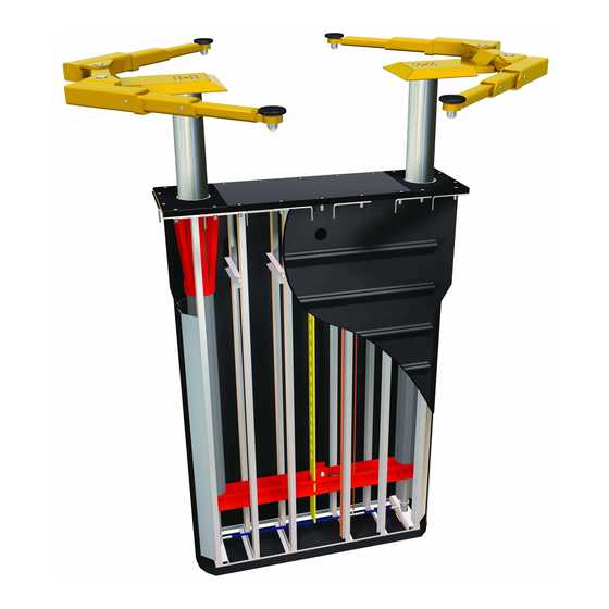
Two Post, Inground, Cassette EnviroLift™
200 Cabel Street, P.O. Box 3944 Louisville, Kentucky 40201-3944
Email:
sales@challengerlifts.com
Office 800-648-5438 / 502-625-0700 Fax 502-587-1933
IMPORTANT:
(10,000 LB CAPACITY – 2500 LB PER ARM)
(12,000 LB CAPACITY – 3000 LB PER ARM)
(15,000 LB CAPACITY – 3750 LB PER ARM)
, O
& M
PERATION
READ THIS MANUAL COMPLETELY BEFORE
INSTALLING or OPERATING LIFT
AINTENANCE
Web site:
www.challengerlifts.com
M
ANUAL
Rev. 6/5/12
EV-IOM-A.doc
Advertisement

Subscribe to Our Youtube Channel
Related Manuals for Challenger Lifts EnviroLift EV1020


Summary of Contents for Challenger Lifts EnviroLift EV1020
- Page 1 MODEL EV1020 (10,000 LB CAPACITY – 2500 LB PER ARM) MODEL EV1220 (12,000 LB CAPACITY – 3000 LB PER ARM) MODEL EV1520 (15,000 LB CAPACITY – 3750 LB PER ARM) & M NSTALLATION PERATION AINTENANCE ANUAL Two Post, Inground, Cassette EnviroLift™ 200 Cabel Street, P.O.
-
Page 2: General Specifications
Models EV1020, EV1220, EV1520 Installation, Operation and Maintenance General Specifications Lifting Time*………………………...…..……..…………..………….(EV1020) Approximately 40 Seconds (EV1220) Approximately 48 Seconds (EV1520) Approximately 60 seconds Lowering Time*..………………………..............Approximately 45 Seconds Motor......……………………......…….....2HP, 230 Volt, Single Phase, 60 Hz Optional-2HP, 240 Volt, 3 Phase, 60 Hz Optional-2HP, 480 Volt, 3 Phase, 60 Hz Dimensions Adapter Height. - Page 3 Models EV1020, EV1220, EV1520 Installation, Operation and Maintenance EV1020, EV1220, EV1520 EV1020MP9 Rev. 6/5/12 EV-IOM-A.doc...
- Page 4 ERTICAL LEARANCE Check the height of the area where the lift is to be installed. Clearance should be calculated based on the full raised height of the lift. Failure by purchaser to provide adequate WARNING clearance could result in unsatisfactory lift performance, property...
- Page 5 If it is apparent that the lift has been mishandled in shipment, or if parts or assemblies are missing, note the damage or missing part(s) on the shipping papers and notify Challenger Lifts, Inc. immediately. The Challenger 2-Post EnviroLift™ consists of two packages, the lift-containment assy.
- Page 6 Models EV1020, EV1220, EV1520 Installation, Operation and Maintenance Installation Procedure Location Locate lift to allow plenty of working room on all sides. Allow room for workbenches at front of bay, aisles, lubrication equipment or other obstructions. Check overhead clearances. Ordinarily 12 feet is ample for automobiles. Observe the recommended minimums in Fig 1.
- Page 7 Models EV1020, EV1220, EV1520 Installation, Operation and Maintenance Existing Facility Excavation Excavation is the same as in new construction. However, it will be necessary to break out a trench 6"-8" wide by 12" deep to run the PVC chase. Installation 1.
- Page 8 Models EV1020, EV1220, EV1520 Installation, Operation and Maintenance 1/2-13 x 18 1/2-13 1/2-13 x 18 1/2-13 All Thread Rod Nut and Washer All Thread Rod Nut and Washer 6 x 6 Support Finished Concrete Tie Anchor Floor Lift / Containment Assembly Existing Floor New Floor...
- Page 9 Models EV1020, EV1220, EV1520 Installation, Operation and Maintenance 6. Before beginning to back fill take care to protect the plunger tops, cover joints and hardware from debris. Duct tape should be used to cover these joints. Make sure all factory supplied thread protectors and caps are in place. Recheck plumb and back fill approximately 2 feet with pea gravel.
- Page 10 Models EV1020, EV1220, EV1520 Installation, Operation and Maintenance Pour concrete floor taking care not to run concrete in or on top of the lift / containment assembly. The floor should slope away from the lift for drainage. The floor slope should not accede 1/16" per foot. DO NOT use the lift until the concrete has fully cured to 3500 psi.
- Page 11 Models EV1020, EV1220, EV1520 Installation, Operation and Maintenance (Normally Open) FIELD CONECTIONS ...
- Page 12 Models EV1020, EV1220, EV1520 Installation, Operation and Maintenance 30 feet of factory assembled air valve. Failure to provide clean, dry lubricated and pressure regulated air will void warranty on pneumatic components. Push ¼” airline through the PVC chase beginning at the power unit. Connect the airline to the appropriate push lock fittings at each end.
- Page 13 Models EV1020, EV1220, EV1520 Installation, Operation and Maintenance check clearance of the foot pad screw to ensure it does not make contact with the floor. Use the height adjustment bolt (see figure 10) to either raise or lower the bolster as necessary. If there is more then 3/8” of clearance on both screws with the bolt fully seated against the bottom of the bolster remove the bolt.
- Page 14 Models EV1020, EV1220, EV1520 Installation, Operation and Maintenance Be sure the adapters are in the lowered position and the arms are parked as seen in Figure 1 before attempting to drive on or off of the lift. Failure to do so may damage the adapters or vehicle.
-
Page 15: Operation Procedure
ANSI/ALI ALOIM-2000, of the questionnaires to: American National Standard for Automotive Lifts- Challenger Lifts, Inc. Safety Requirements for Operation, Inspection and Maintenance. 200 Cabel Street The Owner/Employer shall display the lift Louisville, KY. - Page 16 Models EV1020, EV1220, EV1520 Installation, Operation and Maintenance Maintenance To avoid personal injury, permit only qualified personnel to perform maintenance on this equipment. Maintenance personnel should follow lockout/tagout instructions per ANSI Z244.1. The following maintenance points are suggested as the basis of a routine maintenance program. The actual maintenance program should be tailored to the installation.
-
Page 17: Parts Breakdown
Model EV1020, EV1220, EV1520 IMPORTANT Replace all worn or broken parts with genuine Challenger Lifts, Inc. parts. Contact your local Challenger Lifts parts distributor for pricing and availability. Call Challenger Lifts, Inc. at (502) 625-0700 for the distributor in your area. - Page 18 Models EV1020, EV1220, EV1520 Installation, Operation and Maintenance B17250SLB B17250SRB EV1020 Super Structure Item Part Qty. / Lift Description B2260 Foot Pad Assembly (items 1A-1F) B2208 Rubber Insert B2262 Foot Pad Weld B17256 2 x 30mm Retaining Ring B17257 3 x 45mm Retaining Ring B2261 Threaded Sleeve B17276-1...
- Page 19 Models EV1020, EV1220, EV1520 Installation, Operation and Maintenance EV1020MP9 Super Structure Item Part Qty./Lift Description 16160 CENTER HOLE CAP 16154 7/8” EXT. TOOTH LOCK WASHER 16154 7/8”-9 x 3 1/2" HEX HEAD CAP SCREW P049-68EV PAD BOLSTER CAL044 M10 x 15mm SOCKET HEAD CAP SCREW 10341-28 CAPACITY LABEL, 9000 LBS (2250/PAD) 10341-05L...
- Page 20 Models EV1020, EV1220, EV1520 Installation, Operation and Maintenance 1 1 1 1 3 3 3 3 5 5 5 5 2 2 2 2 7 7 7 7 3 3 3 3 4 4 4 4 8 8 8 8 9 9 9 9 CS1520 SUPER STRUCTURE CS1220 SUPER STRUCTURE...
- Page 21 Models EV1020, EV1220, EV1520 Installation, Operation and Maintenance Containment 1 1 1 1 Item Part Qty./Lift Description 17200 Single Piece Rubber Gasket 16380 Containment Tub (Not Serviceable after Installation) 15009 2" PVC Grommet (Not Serviceable after Installation) 17321 Concrete Tie Weld-Short (Not Serviceable after Installation) 17320 Concrete Tie Weld-Long (Not Serviceable after Installation) Rev.
- Page 22 Models EV1020, EV1220, EV1520 Installation, Operation and Maintenance Bearings Item Part Qty / Lift Description 16116L ½-13 x 2”lg Hex Flange Head Bolt 16485EV Wiper 16486EV Bearing VS5096 1/8 NPT Grease Fitting B17212 Bearing Weld 16132 ¼” x 12” lg Grease Line 17410 ¼”...
- Page 23 Models EV1020, EV1220, EV1520 Installation, Operation and Maintenance Frame Item Part Qty./Lift Description 16157 ½-13 x 1 Frame Support Bolt 16158 ½" External Tooth Lock washer 16159 ½-13 Hex Nut 15010 Hydraulic Line Clamp 16411 Frame Support Weld 16410 Frame Support 16400 Frame Weld (Not Serviceable after Installation) 16413...
- Page 24 Models EV1020, EV1220, EV1520 Installation, Operation and Maintenance Plunger/Rail Assembly Rev. 6/5/12 EV-IOM-A.doc...
- Page 25 Plunger/Rail Assembly Item Part Qty./Lift Description 16480C Chrome Plunger 16154 7/8" Split Lock Washer 16475 7/8-9 x 3 1/2 Socket Head Cap Screw 16138R 2 x 68 Hydraulic RAM Cylinder (EV1020/EV1220) 15075 2.5 x 68 Hydraulic Cylinder (EV1520) 16139 Cylinder Sleeve (EV1020/EV1220) 16483 Synch.
- Page 26 Models EV1020, EV1220, EV1520 Installation, Operation and Maintenance Synchronizing Rail Item # Part # Qty./Lift Description 40142 3/4 x 1 ½ Reverse Single Acting Air Cylinder 40144 1/4-28 Hex Jam Nut 16214 Air Cylinder Clevis 16215 1/4 x 1 ½ Roll Pin 16213 Locking Pawl 36059...
Need help?
Do you have a question about the EnviroLift EV1020 and is the answer not in the manual?
Questions and answers