Table of Contents
Advertisement
Quick Links
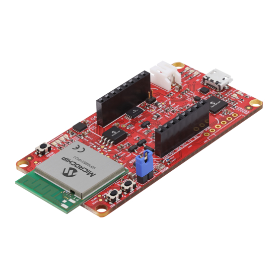
Introduction
The WFI32-IoT board is a compact, stand-alone and easy-to-use board that helps the user to develop the Internet-
of-Things (IoT) applications with the WFI32E01PC module, a highly integrated Wi-Fi
smart Wi-Fi functionalities and premium MCU features. The WFI32E01PC module has a PCB antenna and Trust&GO
hardware secure element, which is pre-provisioned to popular cloud platforms.
The WFI32-IoT board:
•
Provides an easy way to connect the embedded application to cloud IoT platforms, such as AWS and Azure
•
Includes a PICkit On-board 4 (PKOB4) debugger interface, and requires no external hardware to program and
debug the WFI32E01PC module
™
•
Includes a mikroBUS
various MikroElectronika mikroBUS
•
Requires only a Micro USB cable to power up and program the board
Features
•
Certified WFI32E01PC Module
•
Four User LEDs
•
Two User Configurable Switch
•
One Reset Switch
•
On-board Temperature Sensor
•
On-board Light Sensor
•
32-Mbit External SPI Flash Memory
™
•
mikroBUS
Socket to Expand Functionality using MikroElectronika Click Boards
•
Li-Ion/LiPo Battery Charger with Power Path Management
©
2022 Microchip Technology Inc.
and its subsidiaries
WFI32-IoT Board User's Guide
™
Click
header, which helps the users to expand the functionalities by connecting to
™
™
Click
adapter boards
®
User Guide
EV36W50A
MCU module that supports
DS50003262A-page 1
Advertisement
Table of Contents

Related Manuals for Microchip Technology WFI32-IoT


Summary of Contents for Microchip Technology WFI32-IoT
-
Page 1: Introduction
EV36W50A WFI32-IoT Board User's Guide Introduction The WFI32-IoT board is a compact, stand-alone and easy-to-use board that helps the user to develop the Internet- ® of-Things (IoT) applications with the WFI32E01PC module, a highly integrated Wi-Fi MCU module that supports smart Wi-Fi functionalities and premium MCU features. -
Page 2: Table Of Contents
3.8. Ambient Light Sensor......................... 14 3.9. Serial Flash..........................14 3.10. Secondary Oscillator........................15 3.11. WFI32E01PC Module.........................15 WFI32-IoT Board Out of Box Demo...................... 16 Appendix A: Reference Circuit......................17 5.1. WFI32-IoT Board Schematics....................17 5.2. WFI32-IoT Board Bill of Materials....................26 Appendix: B Regulatory Approval...................... - Page 3 EV36W50A Quality Management System........................36 Worldwide Sales and Service........................37 User Guide DS50003262A-page 3 © 2022 Microchip Technology Inc. and its subsidiaries...
-
Page 4: Quick References
(DS20002090) • Universal Serial Bus Specification and Associated Documents (www.usb.org) ™ • mikroBUS Specification (www.mikroe.com/mikrobus) Hardware Prerequisites • EV36W50A (WFI32-IoT board) kit Software Prerequisites ® • MPLAB Integrated Development Environment (MPLAB X IDE) tool (version 5.50 or later) • MPLAB XC32 Compiler (version 2.40 or later) - Page 5 Real Time Clock and Calendar RTOS Real-Time Operating System Receiver Serial Clock Serial Data Surface Mount System-on-Chip Serial Peripheral Interface Transmitter UART Universal Asynchronous Receiver-Transmitter Universal Serial Bus User Guide DS50003262A-page 5 © 2022 Microchip Technology Inc. and its subsidiaries...
-
Page 6: Kit Overview
EV36W50A Kit Overview Kit Overview The WFI32-IoT board has a single-chip Wi-Fi module that supports rapid prototyping of IoT devices and demonstrates cloud connectivity. The WFI32-IoT board: • Offers various types of on-board sensors, such as a temperature sensor and ambient light sensor to build their own applications •... -
Page 7: Kit Contents
EV36W50A Kit Overview Figure 2-2. WFI32-IoT Board (EV36W50A) – Bottom View Voltage Regulator (U104) Power Distribution Switch (U100) Li-Ion/LiPo USB-to-UART Serial Charger (U101) Converter (U202) PKOB4 Main Controller (U300) Temperature Sensor (U402) Secondary Oscillator (Y400) Kit Contents The EV36W50A (WFI32-IoT board) kit contains the following: •... -
Page 8: Hardware
Microchip Sales office. Power Supply The following are the power supply sources to power the WFI32-IoT board; see the following figure: • PKOB4 Micro-B USB (Debug USB) (J200) • Battery Header (J101) - Page 9 ATSAME70N PKOB4 Micro-B USB (Debug USB) (J200) The Debug USB (J200) supplies power to the WFI32-IoT board from the host PC using Type-A male to Micro-B USB cable. Note: The maximum available current from the Debug USB (J200) is limited to 500 mA. The current is shared between charging the external battery (if connected) and the target application section.
-
Page 10: Mplab Pickit On-Board 4 (Pkob4)
3.2.1 Recovery Method When the MPLAB PKOB4 is unresponsive, use the MPLAB X IDE tool to recover the WFI32-IoT board through the following recovery method: Short the pin1 and pin2 of the connector (J301) to the ground for approximately 15 seconds; see the following figure. -
Page 11: Usb Connectivity
(DS50002751) and MPLAB Snap In-Circuit Debugger User's Guide (DS50002787). USB Connectivity The WFI32E01PC module has an integrated full-speed USB peripheral. This feature enables the user to implement USB functionality through the Micro-AB USB connector (J200) on the WFI32-IoT board. User Guide DS50003262A-page 11 ©... -
Page 12: Mikrobus Socket
To have a fully functional UART click board, the R432 and R435 (default) resistors are populated on the WFI32-IoT board. To have a fully functional CAN click board, populate the R433 and R434 resistors on the WFI32-IoT board. To have a fully functional OLED click board, depopulate the R436 resistor on the WFI32-IoT board. -
Page 13: Switches
EV36W50A Hardware Switches The following are the available switches on the WFI32-IoT board: • User-configurable switches – (SW400) and (SW401) • Reset switch (SW402) – Connected with the MCLR signal of the WFI32E01PC module In the Idle state, the level of the user-configurable switch is pulled high (+3.3V) and, when the switch is pressed, it drives the I/O line to low (GND). -
Page 14: Ambient Light Sensor
Alert ASYNC external interrupt TDO/AN7/CVD7/CVDR7/CVDT0/RPB7 Ambient Light Sensor A OPT3001 is a sensor that measures the intensity of visible light. The light sensor is mounted on the WFI32-IoT board for measuring the light intensity. Table 3-5. Light Sensor Pin Name... -
Page 15: Secondary Oscillator
Hardware-based Security Accelerator Data Sheet (DS70005425). Note: The user can configure the Peripheral Pin Select (PPS) pins for any of the supported peripheral functions based on the end user application. User Guide DS50003262A-page 15 © 2022 Microchip Technology Inc. and its subsidiaries... -
Page 16: Wfi32-Iot Board Out Of Box Demo
WFI32-IoT Board Out of Box Demo The WFI32-IoT board’s Out of the Box (OOB) demo is preloaded with a firmware image that enables the user to quickly connect and send data to the AWS cloud using the on-board temperature and light sensors. The users can easily build their own custom projects with software libraries and example codes provided in Harmony v3 framework. -
Page 17: Appendix A: Reference Circuit
EV36W50A Appendix A: Reference Circuit Appendix A: Reference Circuit WFI32-IoT Board Schematics Figure 5-1. Power Distribution Switch for PKOB4 C100 0.1uF VBUS 0402 C101 0.1uF 3V3_PKOB Power Class R101 TP103 U100 0402 VBIAS VOUT R102 C102 0402 VOUT 3V3_PKOB R104... - Page 18 1206 0805 SHDN CDELAY R128 147k C113 0402 PWRGD R126 0603 C114 C115 C116 4.7uF MCP1727/0.8V-5V 200K 0.1uF 4.7uF 0.1uF 0603 0402 0603 0402 R129 PG_SYSTEM PG_SYSTEM 0603 User Guide DS50003262A-page 18 © 2022 Microchip Technology Inc. and its subsidiaries...
- Page 19 CLK_EN R219 ICSP_SPI0_SPCK (ICSP_SCK) R220 330R PGC2/AN4/CVD4/CVDR4/CVDT3/RPB4 0402 74LVC1T45FW4-7 0402 R221 ISP_SPI1_SPCK (SCK_IN) 330R 0402 R223 4.7k R224 0402 3.3k Buffer voltage range is 1.2V to 5..5V 0402 User Guide DS50003262A-page 19 © 2022 Microchip Technology Inc. and its subsidiaries...
- Page 20 0.1uF VCCA VCCB 0201 0201 R225 U3RX ETXEN/CVDT11/RPC13 74LVC1T45FW4-7 0402 3V3_PKOB 3V3_IN C230 C229 U206 0.1uF 0.1uF VCCA VCCB TXD2 0201 0201 RXD2 R226 U3TX ETXD1/CVDT12/RPC14 74LVC1T45FW4-7 0402 User Guide DS50003262A-page 20 © 2022 Microchip Technology Inc. and its subsidiaries...
- Page 21 SCK2/RPA11/RA11 SCK2/RPA11 ANA0/RPB12/RB12 ANA0/RPB12 C416 C415 AN17/CVD17/CVDR17/INT0/RPA10/RA10 INT0/AN17/CVD17/CVDR17/RPA10 22pF 22pF AN15/ANN1/CVD15/CVDR15/RPA13/RA13 ANN1/CVD15/CVDR15/RPA13 AN14/ANN0/CVD14/CVDR14/RPA14/RA14 ANN0/CVD14/CVDR14/RPA14 0201 0201 CAD NOTE All the DATA and CLK lines should have proper GND. User Guide DS50003262A-page 21 © 2022 Microchip Technology Inc. and its subsidiaries...
- Page 22 0402 Figure 5-14. Buttons 3V3_IN 3V3_IN R405 R406 100k 100k 0402 0402 TP416 R437 R438 TP415 0402 0402 PGC4/TCK/AN8/CVD8/CVDR8/RPB8 INT0/AN17/CVD17/CVDR17/RPA10 C409 C408 SW401 10000pF 10000pF SW400 0402 0402 User Guide DS50003262A-page 22 © 2022 Microchip Technology Inc. and its subsidiaries...
- Page 23 I2C address: 0x18 U402 SDA1/RPA5 SCL1/RPA4 C420 TDO/AN7/CVD7/CVDR7/CVDT0/RPB7 Alert 0.1uF MCP9808 0402 Figure 5-17. ICSP HDR J401 3V3_IN NMCLR NMCLR R429 0201 PGD2/AN5/CVD5/CVDR5/CVDT2/RTCC/RPB5 0201 PGC2/AN4/CVD4/CVDR4/CVDT3/RPB4 R430 HDR-2.54 Male 1x6 User Guide DS50003262A-page 23 © 2022 Microchip Technology Inc. and its subsidiaries...
- Page 24 MISO SCL1/RPA4 0402 BT_CLK_OUT/RPK4 MOSI SDA1/RPA5 R436 3V3_IN +3.3V mikroBUS C422 C421 4.7uF R432 4.7uF 0402 U2RX PGD4/TDI/AN9/CVD9/CVDR9/RPB9 0402 0402 R434 R433 0402 0402 R435 0402 PTA_BT_ACTIVE/RPK7 U2TX User Guide DS50003262A-page 24 © 2022 Microchip Technology Inc. and its subsidiaries...
- Page 25 Figure 5-21. User LEDs 3V3_IN R425 D400 ERXDV/CVDT14/RPK12 470R 0402 DATA D401 R426 EMDIO/CVDT15/RPK13 470R YELLOW 0402 D402 CONN R427 EMDC/CVDT16/RPK14 470R GREEN 0402 WIFI D403 R428 0402 ERXERR/CVDT7/RPC9 4.99k BLUE User Guide DS50003262A-page 25 © 2022 Microchip Technology Inc. and its subsidiaries...
-
Page 26: Wfi32-Iot Board Bill Of Materials
EV36W50A Appendix A: Reference Circuit WFI32-IoT Board Bill of Materials The following table provides the Bill of Materials (BOM) of the WFI32-IoT board. Table 5-1. WFI32-IoT Board Bill of Materials Designator Description Manufacturer Manufacturer Part Number C100, C101, C104, Capacitor, ceramic, 0.1 uF, 10V, 10%,... - Page 27 0402 Mechanics America, Inc. ® R108 Resistor, TKF, 47k, 1%, 1/10W, SMD, Panasonic - ECG ERJ-2RKF4702X 0402 R109, R302 Resistor, TKF, 5.62k, 1%, 1/16W, SMD, Vishay/Dale CRCW04025K62FKED 0402 User Guide DS50003262A-page 27 © 2022 Microchip Technology Inc. and its subsidiaries...
- Page 28 Yageo Corporation RC0402FR-07100RL 0402 R307, R425, R426, Resistor, TKF, 470R, 5%, 1/16W, SMD, Yageo Corporation RC0402JR-07470RL R427 0402 R404, R412 Resistor, TKF, 10k, 1%, 1/10W, SMD, Panasonic ERJ-2RKF1002X 0402 User Guide DS50003262A-page 28 © 2022 Microchip Technology Inc. and its subsidiaries...
- Page 29 MB, 384K x 8, ATSAME70N21B-CNT, Technology Inc. TFBGA-100 U301 Microchip, Memory serial, EEPROM, Microchip 24LC256T-E/ST 256k, I C, 24LC256T-E/ST, TSSOP-8 Technology Inc. U400 MOD, Wi-Fi, WFI32E01PCI Microchip WFI32E01PCI Technology Inc. User Guide DS50003262A-page 29 © 2022 Microchip Technology Inc. and its subsidiaries...
- Page 30 Mechanical, hardware, Nut, M3, Nylon Keystone 4688 NUT102, NUT103 Electronics Corp. ™ STANDOFF100, Mechanical, hardware, Stand-off, M, Duratool D01496 STANDOFF101, 3x10 mm, M/F, Thread, 6 mm Hex, 5.5 STANDOFF102, mm Nylon STANDOFF103 User Guide DS50003262A-page 30 © 2022 Microchip Technology Inc. and its subsidiaries...
-
Page 31: Appendix: B Regulatory Approval
Appendix: B Regulatory Approval This equipment (WFI32-IoT Board/EV36W50A) is an evaluation kit and not a finished product. It is intended for laboratory evaluation purposes only. It is not directly marketed or sold to the general public through retail; it is only sold through authorized distributors or through Microchip. -
Page 32: Europe
Radio Equipment Directive (RED). Simplified EU Declaration of Conformity Hereby, Microchip Technology Inc. declares that the radio equipment type [EV36W50A] is in compliance with Directive 2014/53/EU. The full text of the EU declaration of conformity is available at www.microchip.com/en-us/development-tool/... -
Page 33: Document Revision History
EV36W50A Document Revision History Document Revision History Revision Date Section Description 02/2022 Document Initial Revision User Guide DS50003262A-page 33 © 2022 Microchip Technology Inc. and its subsidiaries... -
Page 34: The Microchip Website
It is your responsibility to ensure that your application meets with your specifications. Contact your local Microchip sales office for additional support or, obtain additional support at www.microchip.com/en-us/support/ design-help/client-support-services. User Guide DS50003262A-page 34 © 2022 Microchip Technology Inc. and its subsidiaries... -
Page 35: Trademarks
The Adaptec logo, Frequency on Demand, Silicon Storage Technology, Symmcom, and Trusted Time are registered trademarks of Microchip Technology Inc. in other countries. GestIC is a registered trademark of Microchip Technology Germany II GmbH & Co. KG, a subsidiary of Microchip Technology Inc., in other countries. - Page 36 EV36W50A Quality Management System For information regarding Microchip’s Quality Management Systems, please visit www.microchip.com/quality. User Guide DS50003262A-page 36 © 2022 Microchip Technology Inc. and its subsidiaries...
- Page 37 Tel: 631-435-6000 Sweden - Stockholm San Jose, CA Tel: 46-8-5090-4654 Tel: 408-735-9110 UK - Wokingham Tel: 408-436-4270 Tel: 44-118-921-5800 Canada - Toronto Fax: 44-118-921-5820 Tel: 905-695-1980 Fax: 905-695-2078 User Guide DS50003262A-page 37 © 2022 Microchip Technology Inc. and its subsidiaries...
Need help?
Do you have a question about the WFI32-IoT and is the answer not in the manual?
Questions and answers