Table of Contents
Advertisement
Quick Links
Advertisement
Table of Contents

Related Manuals for Microchip Technology PT100 RTD


Summary of Contents for Microchip Technology PT100 RTD
-
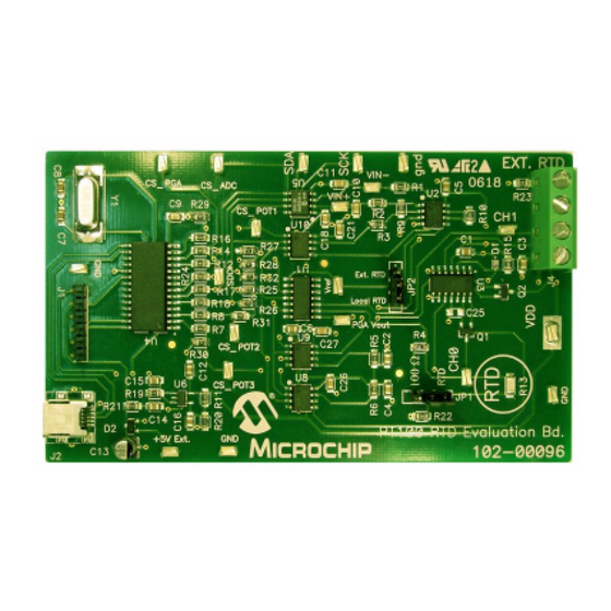
Page 1: Evaluation Board
PT100 RTD Evaluation Board User’s Guide © 2006 Microchip Technology Inc. DS51607A... - Page 2 Microchip products meet the specification contained in their particular Microchip Data Sheet. • Microchip believes that its family of products is one of the most secure families of its kind on the market today, when used in the intended manner and under normal conditions.
-
Page 3: Table Of Contents
Chapter 1. Product Overview ..................5 1.1 Introduction ..................... 5 1.2 What is the PT100 RTD Evaluation Board? ........... 5 1.3 What the PT100 RTD Evaluation Board Kit Includes ........5 Chapter 2. Installation and Operation ................. 7 2.1 Introduction ..................... 7 2.2 Features ...................... - Page 4 PT100 RTD Evaluation Board User’s Guide NOTES: © 2006 Microchip Technology Inc. DS51607A-page iv...
-
Page 5: Preface
• Document Revision History DOCUMENT LAYOUT This document describes how to use the PT100 RTD Evaluation Board as a develop- ment tool. The manual layout is as follows: • Chapter 1. “Product Overview” – Important information about the PT100 RTD Evaluation Board. -
Page 6: Conventions Used In This Guide
PT100 RTD Evaluation Board User’s Guide CONVENTIONS USED IN THIS GUIDE This manual uses the following documentation conventions: DOCUMENTATION CONVENTIONS Description Represents Examples Arial font: ® Italic characters Referenced books MPLAB IDE User’s Guide Emphasized text ...is the only compiler... -
Page 7: Recommended Reading
Preface RECOMMENDED READING This user's guide describes how to use the PT100 RTD Evaluation Board. The following Microchip documents are available on our web site (www.microchip.com) and recommended as supplemental reference resources. MCP6S26 Data Sheet, “Single-Ended, Rail-toRail I/O, Low Gain PGA“ (DS21117) This data sheet provides detailed information regarding the MCP6S26 device. -
Page 8: Customer Support
PT100 RTD Evaluation Board User’s Guide CUSTOMER SUPPORT Users of Microchip products can receive assistance through several channels: • Distributor or Representative • Local Sales Office • Field Application Engineer (FAE) • Technical Support • Development Systems Information Line Customers should contact their distributor, representative or field application engineer for support. -
Page 9: Chapter 1. Product Overview
BOARD USER’S GUIDE Chapter 1. Product Overview INTRODUCTION This chapter provides an overview of the PT100 RTD Evaluation Board and covers the following topics: • What is the PT100 RTD Evaluation Board? • What the PT100 RTD Evaluation Board kit includes. - Page 10 PT100 RTD Evaluation Board User’s Guide NOTES: © 2006 Microchip Technology Inc. DS51607A-page 6...
-
Page 11: Chapter 2. Installation And Operation
Chapter 2. Installation and Operation INTRODUCTION The PT100 RTD Evaluation Board allows the user to evaluate Microchip’s solution to accurately measure temperature using RTD. When biasing RTDs to measure temperature, self-heat due to power dissipation has to be considered. RTD resistance availability typically ranges from 100Ω... -
Page 12: Getting Started
PT100 RTD Evaluation Board User’s Guide GETTING STARTED This section describes how to quickly configure the PT100 RTD Evaluation Board. A simplified block diagram of the configuration is provided in Figure 2-1. PT100 RTD Evaluation Board Diff Amp FIGURE 2-1: PT100 RTD Evaluation Board Simplified Block Diagram. - Page 13 4. Click start to start acquisition, stop to stop acquisition. Reset to Clear buffer. 5. Adjust the digital potentiometer positions to select the differential amplifier gain and trim the current sources for the local and external RTDs. © 2006 Microchip Technology Inc. DS51607A-page 9...
-
Page 14: Functional Description
PT100 RTD Evaluation Board uses surface mount RTD to measure tempera- ture. An external 2, 3 or 4-wire PT100 RTD can also be connected to measure temper- ature in remote locations. The RTDs are biased using a constant current source. In order to reduce self-heat due to power dissipation, the current magnitude is relatively low. - Page 15 When start is clicked, the macro double checks hardware availability before starting the acquisition. All user options such as Sampling time, Stripchart buffer size, Digi. Pot Positions, or PGA Chn/Gain setup can be changed during acquisition. © 2006 Microchip Technology Inc. DS51607A-page 11...
- Page 16 PT100 RTD Evaluation Board User’s Guide NOTES: © 2006 Microchip Technology Inc. DS51607A-page 12...
-
Page 17: Appendix A. Schematic And Layouts
PT100 RTD EVALUATION BOARD USER’S GUIDE Appendix A. Schematic and Layouts INTRODUCTION This appendix contains the following schematics and layouts for the PT100 RTD Evaluation Board: • Board Schematic • Board - Top Layer • Board - Silk-screen Layer • Board - Bottom Layer ©... -
Page 18: Board Schematic
PT100 RTD Evaluation Board User’s Guide BOARD SCHEMATIC - PAGE 1 © 2006 Microchip Technology Inc. DS51607A-page 14... -
Page 19: Board Schematic
Schematic and Layouts BOARD SCHEMATIC - PAGE 2 © 2006 Microchip Technology Inc. DS51607A-page 15... -
Page 20: Board - Top Silk-Screen Layer
PT100 RTD Evaluation Board User’s Guide BOARD - TOP SILK-SCREEN LAYER BOARD - TOP LAYER © 2006 Microchip Technology Inc. DS51607A-page 16... -
Page 21: Board - Bottom Silk
Schematic and Layouts BOARD - BOTTOM SILK BOARD - BOTTOM LAYER © 2006 Microchip Technology Inc. DS51607A-page 17... - Page 22 PT100 RTD Evaluation Board User’s Guide NOTES: © 2006 Microchip Technology Inc. DS51607A-page 18...
-
Page 23: Appendix B. Bill Of Materials (Bom)
Panasonic - ECG ERJ-6ENF1002V ® RES 1.80M OHM 1/8W 1% 0805 Yageo America RC0805FR-071M8L PLATINUM RTD CHIP ENERCORP Model: PCS 1.1503.1 TEMPERATURE SENSOR SMD enercorp.com RES 35.7K OHM 1/8W 1% 0805 Panasonic - ECG ERJ-6ENF3572V © 2006 Microchip Technology Inc. DS51607A-page 19... - Page 24 PT100 RTD Evaluation Board User’s Guide TABLE B-1: BILL OF MATERIALS (CONTINUED) Reference Description Manufacturer Part Number R18, R22, RES 1.00K OHM 1/10W 1% 0805 Panasonic - ECG ERJ-6ENF1001V R19, R21 RES 10.0 OHM 1/8W 1% 0805 SMD Panasonic - ECG...
- Page 25 Bill Of Materials (BOM) NOTES: © 2006 Microchip Technology Inc. DS51607A-page 21...
-
Page 26: Worldwide Sales And Service
Fax: 949-462-9608 Tel: 886-2-2500-6610 Fax: 86-29-8833-7256 San Jose Fax: 886-2-2508-0102 Mountain View, CA Thailand - Bangkok Tel: 650-215-1444 Tel: 66-2-694-1351 Fax: 650-961-0286 Fax: 66-2-694-1350 Toronto Mississauga, Ontario, Canada Tel: 905-673-0699 Fax: 905-673-6509 02/16/06 © 2006 Microchip Technology Inc. DS51607A-page 22...
Need help?
Do you have a question about the PT100 RTD and is the answer not in the manual?
Questions and answers