
Related Manuals for Microchip Technology MCP6 series


Summary of Contents for Microchip Technology MCP6 series
- Page 1 MCP6XXX Amplifier Evaluation Board 3 User’s Guide © 2007 Microchip Technology Inc. DS51673A...
- Page 2 Microchip products meet the specification contained in their particular Microchip Data Sheet. • Microchip believes that its family of products is one of the most secure families of its kind on the market today, when used in the intended manner and under normal conditions.
-
Page 3: Table Of Contents
Chapter 1. Product Overview ..................5 1.1 Introduction ..................... 5 1.2 MCP6XXX Amplifier Evaluation Board 3 Kit Contents ........5 1.3 Microchip’s Web-Based Mindi™ Analog Simulator Tool ........ 6 1.4 MCP6XXX Amplifier Evaluation Board 3 Description ........6 Chapter 2. Installation and Operation ................. 7 2.1 Introduction ..................... - Page 4 MCP6XXX Amplifier Evaluation Board 3 User’s Guide NOTES: © 2007 Microchip Technology Inc. DS51673A-page iv...
-
Page 5: Preface
Preface NOTICE TO CUSTOMERS All documentation becomes dated, and this manual is no exception. Microchip tools and documentation are constantly evolving to meet customer needs, so some actual dialogs and/or tool descriptions may differ from those in this document. Please refer to our web site (www.microchip.com) to obtain the latest documentation available. -
Page 6: Conventions Used In This Guide
Curly brackets and pipe Choice of mutually exclusive errorlevel {0|1} character: { | } arguments; an OR selection Ellipses... Replaces repeated text var_name [, var_name...] Represents code supplied by void main (void) user { ... © 2007 Microchip Technology Inc. DS51673A-page 2... -
Page 7: Recommended Reading
This data sheet provides detailed information regarding the MCP602X product family. THE MICROCHIP WEB SITE Microchip provides online support via our web site at www.microchip.com. This web site is used as a means to make files and information easily available to customers. - Page 8 MCP6XXX Amplifier Evaluation Board 3 User’s Guide NOTES: © 2007 Microchip Technology Inc. DS51673A-page 4...
-
Page 9: Chapter 1. Product Overview
Items discussed in this chapter include: • Section 1.2 “MCP6XXX Amplifier Evaluation Board 3 Kit Contents” • Section 1.3 “Microchip’s Web-Based Mindi™ Analog Simulator Tool” • Section 1.4 “MCP6XXX Amplifier Evaluation Board 3 Description” MCP6XXX AMPLIFIER EVALUATION BOARD 3 KIT CONTENTS •... -
Page 10: Microchip's Web-Based Mindi™ Analog Simulator Tool
“Online Simulation Tools” or by going directly to the Mindi web site at http://www.microchip.com/mindi. The circuit simulator within the Mindi™ Analog Simulator tool can be downloaded and installed on a personal computer (PC) for more convenient simulations. Modified circuit files can also be downloaded to the PC. -
Page 11: Chapter 2. Installation And Operation
3. Figure 2-1 shows the circuit diagram for the board. * Test Points Mid-supply Reference Block VREF 0.1 µF Power Supply 1.0 µF RISO Source Configuration Block FIGURE 2-1: MCP6XXX Amplifier Evaluation Board 3 Circuit Diagram. © 2007 Microchip Technology Inc. DS51673A-page 7... - Page 12 The power supply voltage needs to be in the allowed range for the installed op amps. Any of Microchip’s op amps that operate below 5.5V can be used. Moreover, the power supply is protected by a zener diode with nominal voltage 6.2V and bypassed by a 1.0 µF capacitor.
- Page 13 The mid-supply reference consists of a voltage divider and a buffer amplifier. Figure 2-4 shows the circuit diagram for the mid-supply reference. = 0.1 µF, R = 20.0 kΩ. Mid-supply Reference FIGURE 2-4: Mid-Supply Reference Block. © 2007 Microchip Technology Inc. DS51673A-page 9...
- Page 14 R is used to stabilize the amplifier when it drives a large capacitive load (C ). R is a short circuit (0Ω) when C is small. Output Load FIGURE 2-5: Output Load Block. © 2007 Microchip Technology Inc. DS51673A-page 10...
- Page 15 • Source configuration consists of an inverting amplifier and a jumper. Figure 2-4 shows the circuit diagram for the source configuration. = 0.1 uF, R = 20.0 kΩ, R = 10.0 kΩ Source Configuration FIGURE 2-7: Source Configuration Block. © 2007 Microchip Technology Inc. DS51673A-page 11...
- Page 16 * Test Points Mid-supply Reference Block VREF 0.1 µF Power Supply 1.0 µF RISO Source Configuration Block FIGURE 2-8: Difference Amplifier Example Supported by the MCP6XXX Amplifier Evaluation Board 3. © 2007 Microchip Technology Inc. DS51673A-page 12...
-
Page 17: Mcp6Xxx Amplifier Evaluation Board 3 Operation
• Power Supply Voltage is 5.0V • Differential Mode Input Signal • Desired Closed Loop Gain is 1 V/V • Load Capacitance is 56 pF FIGURE 2-9: Difference Amplifier Designed In the Mindi™ Amplifier Designer. © 2007 Microchip Technology Inc. DS51673A-page 13... - Page 18 1.98 kΩ RISO 0Ω 1.98 kΩ 56 pF MCP6021, PDIP-8, 10 MHz For the differential mode input signal, the jumper JP position is listed in Table 2-2. TABLE 2-2: JUMPER POSITION Jumper Position JPS1 © 2007 Microchip Technology Inc. DS51673A-page 14...
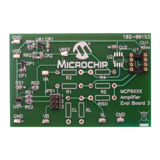
- Page 19 MCP6XXX Amplifier Evaluation Board 3. The fully assembled MCP6XXX Amplifier Evaluation Board 3 top view is shown in Figure 2-12. FIGURE 2-12: Picture of the Difference Amplifier Supported by the MCP6XXX Amplifier Evaluation Board 3. © 2007 Microchip Technology Inc. DS51673A-page 15...
- Page 20 Figure 2-13 shows the test points to check. VREF Test Point Test Point Test Point Test Point Test Point Test Point Test Point Test Point FIGURE 2-13: Checking the Test Points. © 2007 Microchip Technology Inc. DS51673A-page 16...
- Page 21 2.0V above center Note: The center voltage of V is set at V /2 (For V = 5.0V, = 2.5V) = 4.5V = 3.5V = 2.5V FIGURE 2-14: Measured Step Response. © 2007 Microchip Technology Inc. DS51673A-page 17...
- Page 22 2.0V above center) Note: The center voltage of V is set at V /2 (For V = 5.0V, = 2.5V) = 4.5V = 3.5V = 2.5V FIGURE 2-15: Simulated Step Response. © 2007 Microchip Technology Inc. DS51673A-page 18...
- Page 23 100.0 Hz, a peak-to-peak voltage of 4.0V and a center voltage of 2.5V Note: The center voltage of V is set at V /2 (For V = 5.0V, = 2.5V) FIGURE 2-16: Measured Sine Wave Response. © 2007 Microchip Technology Inc. DS51673A-page 19...
- Page 24 100.0 Hz, a peak-to-peak voltage of 4.0V and a center voltage of 2.5V Note: The center voltage of V is set at V /2 (For V = 5.0V, = 2.5V) FIGURE 2-17: Simulated Sine Wave Response. © 2007 Microchip Technology Inc. DS51673A-page 20...
- Page 25 Evaluation Board 3. Figure 2-19 shows a SOIC-8 op amp and a DIP-8 socket, soldered onto the 8-Pin SOIC/MSOP/TSSOP/DIP Evaluation Board available from Microchip Technology Inc. (order # SOIC8EV). The two interconnect strips on the bottom are Samtec part # BBS-14-T-B or equivalent and are soldered into the through holes for the DIP-8 socket.
- Page 26 MCP6XXX Amplifier Evaluation Board 3 User’s Guide (Back View) (Front View) FIGURE 2-19: Op Amp in SOIC-8 package soldered onto a separate board. FIGURE 2-20: Connecting Adaptor Board onto MCP6XXX Amplifier Evaluation Board 3. © 2007 Microchip Technology Inc. DS51673A-page 22...
-
Page 27: Appendix A. Schematic And Layouts
This appendix contains the following schematics and layouts for the MCP6XXX Ampli- fier Evaluation Board 3: • Board – Schematic • Board – Top Silk Layer • Board – Top Trace and Silk Layer • Board – Bottom Layer © 2007 Microchip Technology Inc. DS51673A-page 23... -
Page 28: Board - Schematic
MCP6XXX Amplifier Evaluation Board 3 User’s Guide BOARD - SCHEMATIC © 2007 Microchip Technology Inc. DS51673A-page 24... -
Page 29: Board - Top Silk Layer
Schematic and Layouts BOARD - TOP SILK LAYER © 2007 Microchip Technology Inc. DS51673A-page 25... -
Page 30: Board - Top Trace And Silk
MCP6XXX Amplifier Evaluation Board 3 User’s Guide BOARD - TOP TRACE AND SILK © 2007 Microchip Technology Inc. DS51673A-page 26... -
Page 31: Board - Bottom Layer
Schematic and Layouts BOARD - BOTTOM LAYER © 2007 Microchip Technology Inc. DS51673A-page 27... - Page 32 MCP6XXX Amplifier Evaluation Board 3 User’s Guide NOTES: © 2007 Microchip Technology Inc. DS51673A-page 28...
-
Page 33: Appendix B. Bill Of Materials (Bom)
CONN IC SOCKET 8POS DIP Tyco Electronics/Amp 2-641260-1 Note 1: The components listed in this Bill of Materials are representative of the PCB assembly. The released BOM used in manufacturing uses all RoHS-compliant components. © 2007 Microchip Technology Inc. DS51673A-page 29... - Page 34 ESD Sample Box MCP6021 Single OpAmp Microchip Technology Inc MCP6021-E/P PDIP-8 Note 1: The components listed in this Bill of Materials are representative of the PCB assembly. The released BOM used in manufacturing uses all RoHS-compliant components. © 2007 Microchip Technology Inc. DS51673A-page 30...
- Page 35 Bill of Materials (BOM) NOTES: © 2007 Microchip Technology Inc. DS51673A-page 31...
-
Page 36: Worldwide Sales And Service
China - Wuhan Thailand - Bangkok Tel: 408-961-6444 Tel: 86-27-5980-5300 Tel: 66-2-694-1351 Fax: 408-961-6445 Fax: 86-27-5980-5118 Fax: 66-2-694-1350 Toronto China - Xian Mississauga, Ontario, Tel: 86-29-8833-7252 Canada Fax: 86-29-8833-7256 Tel: 905-673-0699 Fax: 905-673-6509 06/25/07 © 2007 Microchip Technology Inc. DS51673A-page 32...
Need help?
Do you have a question about the MCP6 series and is the answer not in the manual?
Questions and answers