
Related Manuals for Microchip Technology MCP2221


Summary of Contents for Microchip Technology MCP2221
- Page 1 MCP2221 C Demonstration Board User’s Guide 2016 Microchip Technology Inc. DS50002480A Arrow.com. Downloaded from...
- Page 2 WiperLock, Wireless DNA, and ZENA are trademarks of Microchip Technology Incorporated in the U.S.A. and other countries. SQTP is a service mark of Microchip Technology Incorporated in the U.S.A. Microchip received ISO/TS-16949:2009 certification for its worldwide Silicon Storage Technology is a registered trademark of headquarters, design and wafer fabrication facilities in Chandler and Microchip Technology Inc.
- Page 3 Object of Declaration: MCP2221 I C Demonstration Board User’s Guide 2016 Microchip Technology Inc. DS50002480A-page 3 Arrow.com. Arrow.com. Arrow.com. Downloaded from Downloaded from Downloaded from...
- Page 4 MCP2221 I C Demonstration Board User’s Guide NOTES: 2016 Microchip Technology Inc. DS50002480A-page 4 Arrow.com. Arrow.com. Arrow.com. Arrow.com. Downloaded from Downloaded from Downloaded from Downloaded from...
-
Page 5: Table Of Contents
C Slave Addresses ..................41 Chapter 5. Troubleshooting 5.1 Board Not Detected by PC ................43 5.2 USB Driver Installation Issues ..............43 5.3 PC Application Reports “MCP2221 Not Connected” ........43 5.4 PC Application Reports I C Errors ............... 44 ®... - Page 6 A.7 Board – Bottom Copper ................49 A.8 Board – Bottom Copper and Silk ..............50 A.9 Board – Bottom Silk ..................50 Appendix B. Bill of Materials (BOM) ................51 Worldwide Sales and Service ..................54 2016 Microchip Technology Inc. DS50002480A-page 6 Arrow.com. Arrow.com. Arrow.com.
-
Page 7: Preface
Customer Support • Document Revision History DOCUMENT LAYOUT This document describes how to use the MCP2221 I C Demonstration Board as an evaluation tool to debug a target motor system. The manual layout is as follows: • – Important information on the board. -
Page 8: Conventions Used In This Guide
{ | } arguments; an OR selection Ellipses... Replaces repeated text var_name [, var_name...] Represents code supplied by void main (void) user { ... 2016 Microchip Technology Inc. DS50002480A-page 8 Arrow.com. Arrow.com. Arrow.com. Arrow.com. Arrow.com. Arrow.com. Arrow.com. Arrow.com. -
Page 9: Recommended Reading
Preface RECOMMENDED READING This user’s guide describes how to use the MCP2221 I C Demonstration Board. Other useful documents are listed below. The following Microchip documents are available and recommended as a supplemental reference resource. • MCP2221 Data Sheet – “USB 2.0 to I C™/UART/Protocol Converter with GPIO”... - Page 10 MCP2221 I C Demonstration Board User’s Guide NOTES: 2016 Microchip Technology Inc. DS50002480A-page 10 Arrow.com. Arrow.com. Arrow.com. Arrow.com. Arrow.com. Arrow.com. Arrow.com. Arrow.com. Arrow.com. Arrow.com. Downloaded from Downloaded from Downloaded from Downloaded from Downloaded from Downloaded from Downloaded from Downloaded from...
-
Page 11: Chapter 1. Product Overview
(EEPROM) • Output voltage level control of the MCP4726 Digital-to-Analog Converter (DAC) • Creating a USB to RS-232 bridge, based on the MCP2221 device and a Texas Instrument’s MAX3232 transceiver; alternately creating a USB to UART bridge to the PIC16F1509 microcontroller ... - Page 12 PIC16F1509 for custom applications. 1.2.3 C Devices Available on the Board Table 1-1 identifies the I C devices (master and slaves) available on the MCP2221 I Demonstration Board. TABLE 1-1: C DEVICES AVAILABLE ON THE MCP2221 BOARD Device...
-
Page 13: What The Mcp2221 I 2 C Demonstration Board Kit Includes
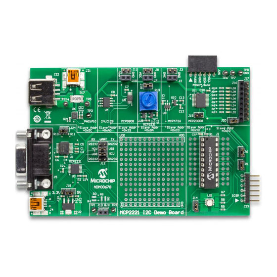
Figure 1-1 illustrates the components on the top view. FIGURE 1-1: MCP2221 TOP VIEW – I C DEVICES ON THE BOARD 24LC128 MCP3221 MCP23008 PAC1710 MCP4726 MCP9808 MCP2221 PIC16F1509 WHAT THE MCP2221 I C DEMONSTRATION BOARD KIT INCLUDES The MCP2221 I C Demonstration Board Kit (ADM00678) includes: •... - Page 14 MCP2221 I C Demonstration Board User’s Guide NOTES: 2016 Microchip Technology Inc. DS50002480A-page 14 Arrow.com. Arrow.com. Arrow.com. Arrow.com. Arrow.com. Arrow.com. Arrow.com. Arrow.com. Arrow.com. Arrow.com. Arrow.com. Arrow.com. Arrow.com. Arrow.com. Downloaded from Downloaded from Downloaded from Downloaded from Downloaded from Downloaded from...
-
Page 15: Chapter 2. Installation And Operation
1. Check if the board is properly powered from USB by setting jumper J19 to either 5V or 3.3V; by default, it is set to 5V. 2. Connect the MCP2221 I C Demonstration Board to a PC through the mini-USB port (J4). -
Page 16: Jumpers And Connectors Description
MCP2221 I C Demonstration Board User’s Guide 2016 Microchip Technology Inc. DS50002480A-page 16 Arrow.com. Arrow.com. Arrow.com. Arrow.com. Arrow.com. Arrow.com. Arrow.com. Arrow.com. Arrow.com. Arrow.com. Arrow.com. Arrow.com. Arrow.com. Arrow.com. Arrow.com. Arrow.com. Downloaded from Downloaded from Downloaded from Downloaded from Downloaded from... - Page 17 Jumper for configuring the UART/RS-232 traffic directions: • MCP2221 to PIC16F1509: Short-circuit (RX MCU) with (TX USB), then (TX MCU) with (RX USB). This is the default setting. • MCP2221 to RS232: Short-circuit (RX RS-232) with (RX USB), then (TX RS-232) with (TX USB).
-
Page 18: Test Points Description
MCP2221 I C Demonstration Board User’s Guide TABLE 2-1: MCP2221 BOARD JUMPERS CONFIGURATION (CONTINUED) Jumper Function Description Designator Jumper enabling the 4.7 pull-up resistors for the I C data (SDA) and clock (SCL) lines on the board. Consider removing it if the demonstration board connects to an external I... -
Page 19: Chapter 3. Testing Board Features
Section 2.2 “Board Setup”. ABOUT THE MPC2221 I C DEMO BOARD APPLICATION The PC application for the device is named the MCP2221 I C Demo Board Application. The three main sections that can be observed in Figure 3-1 are the Feature tabs, General Information panel and Setup area. -
Page 20: General Information Panel Description
Click the Clear I2C Status Box button to clear the I2C Communication Status box. Note that clearing the text in the box does not cancel or revert any previously performed action. 2016 Microchip Technology Inc. DS50002480A-page 20 Arrow.com. Arrow.com. -
Page 21: Feature Tabs
The charging current is provided by a digital output pin of the MCP2221 board and limited by a 470 kΩ resistor. The Measure R, C tab also generates a charging graph for the capacitor, as well as an indicator of its voltage. - Page 22 C Demonstration Board Kit is not recommended for precision measurements. • For both capacitor and resistance measurements, voltages are generated by digital output pins and measured using the analog input pins of the MCP2221 I Demonstration Board. 2016 Microchip Technology Inc.
- Page 23 Prior to measuring the current/power of the USB device, make sure that: • The load to be measured (for example a USB mouse) is connected to the MCP2221 board’s USB socket marked with J22 • The power source (such as the PC) is connected to the mini-USB socket marked with J21 3.3.2.1...
- Page 24 USB Flash drive when connected to the PC via the measuring circuit. FIGURE 3-6: MEASURING CURRENT, VOLTAGE AND POWER OF A USB DEVICE 2016 Microchip Technology Inc. DS50002480A-page 24 Arrow.com. Arrow.com.
- Page 25 (devices) that do not draw a current above ~2.5A. • A shunt resistor of 0.025Ω is used, which sets the PAC1710 chip’s full-scale cur- rent value to 3.2A. However, current limitations are also imposed by the MCP2221 board’s design.
- Page 26 LED blinking on the board. Custom LED notifications are described in Section 3.3.8 “RGB LED Notifications Tab”. Figure 3-7 shows an example for measuring the temperature in °C. FIGURE 3-7: TEMPERATURE MEASUREMENT 2016 Microchip Technology Inc. DS50002480A-page 26 Arrow.com. Arrow.com. Arrow.com. Arrow.com. Arrow.com.
- Page 27 The MCP9808 temperature sensor can be configured to output an alert signal when the temperature changes beyond the specified boundary limits. The signal can be read on the MCP2221 board through the pin extensions marked with J10 and J11. More information is available in Section 2.3 “Jumpers and Connectors...
- Page 28 The Erase All EEPROM Data button resets the entire content of the EEPROM to 0xFF. The Reset Entire Table to 0xFF button only affects the displayed matrix, not the actual EEPROM memory. 2016 Microchip Technology Inc. DS50002480A-page 28 Arrow.com.
- Page 29 Custom LED notifications (for example: voltage readings above 2.31V results in a green LED blinking on the board) are described in Section 3.3.8 “RGB LED Notifications Tab”. 2016 Microchip Technology Inc. DS50002480A-page 29 Arrow.com. Arrow.com. Arrow.com. Arrow.com.
- Page 30 MCP2221 I C Demonstration Board User’s Guide Figure 3-9 shows an example for measuring the voltage: FIGURE 3-9: VOLTAGE MEASUREMENT 2016 Microchip Technology Inc. DS50002480A-page 30 Arrow.com. Arrow.com. Arrow.com. Arrow.com. Arrow.com. Arrow.com. Arrow.com. Arrow.com. Arrow.com. Arrow.com. Arrow.com. Arrow.com. Arrow.com.
- Page 31 5. To read the output voltage value back from the chip’s register, click the Read Voltage Data button. The value is displayed in the read-only text box, below the “Current Voltage” label. 2016 Microchip Technology Inc. DS50002480A-page 31 Arrow.com.
- Page 32 Custom LED notifications for pin GP0 (for example: the pin having a logical high state results in a yellow LED blinking on the board) are described in Section 3.3.8 “RGB LED Notifications Tab”. 2016 Microchip Technology Inc. DS50002480A-page 32 Arrow.com. Arrow.com. Arrow.com.
- Page 33 Every 100ms” check box is selected; • Manually, by clicking on the Read Pin States button. Figure 3-11 shows an example of using the GPIO Expander tab. FIGURE 3-11: INTERFACING THE GPIO EXPANDER 2016 Microchip Technology Inc. DS50002480A-page 33 Arrow.com. Arrow.com. Arrow.com. Arrow.com.
- Page 34 Pulse-Width Modulation (PWM) pins of the PIC16F1509, which receives commands (as I C slave) from the MCP2221 DLL through the MCP2221 board. The LED color and brightness are configured from the PC application. It is recommended to avoid light color tones, because they can translate into very intense LED brightness.
- Page 35 7. Optional. Users can also click the Save Preferences into EERPROM button to save the current created configuration inside the 24LC128 EEPROM that’s on the MCP2221 board (data is stored inside its last memory page, 255). Also, the Load Preferences from EEPROM button can be used to restore configurations from the EEPROM.
- Page 36 C Demonstration Board User’s Guide Figure 3-13 shows how the LED is configured to blink (blue color) in case the measured USB current exceeds 85 mA. FIGURE 3-13: CONFIGURING LED NOTIFICATIONS 2016 Microchip Technology Inc. DS50002480A-page 36 Arrow.com. Arrow.com. Arrow.com. Arrow.com.
- Page 37 2. Click the Get COM Ports Info button for the system to display information (in the text box below it) about the COM ports present in the system; this can be used to determine the COM port number of the MCP2221 USB to I C/UART converter from the demonstration board.
- Page 38 C Demonstration Board User’s Guide Figure 3-14 shows an example of sending the text ‘12’ to the PIC microcontroller and receiving ‘23’ back. FIGURE 3-14: UART COMMUNICATION WITH THE PIC16F1509 2016 Microchip Technology Inc. DS50002480A-page 38 Arrow.com. Arrow.com. Arrow.com. Arrow.com.
-
Page 39: Usb To I
C/SMBus Terminal for Windows or the MCP2221 Terminal Android Application for Android. In order to create a custom application (GUI), the user can call the MCP2221 associ- ated functions (for its configuration or actual data transfer) through the DLL files that can be downloaded from the same location. -
Page 40: Pic16F1509 As I C Master
C bus by short-circuiting jumpers J6 and J9. • The I C data and clock lines’ pull-up resistors are connected; if no pull-up resistors are externally connected to the board, then jumper J24 must be connected. 2016 Microchip Technology Inc. DS50000000A-page 40 Arrow.com. Arrow.com. Arrow.com. -
Page 41: C Slave Addresses
0x40 0x41 MCP3221 0x9A 0x9B MCP4726 0xC0 0xC1 MCP9808 0x32 0x33 PAC1710 0x5C 0x5D PIC16F1509 0x10 0x11 2016 Microchip Technology Inc. DS50000000A-page 41 Arrow.com. Arrow.com. Arrow.com. Arrow.com. Arrow.com. Arrow.com. Arrow.com. Arrow.com. Arrow.com. Arrow.com. Arrow.com. Arrow.com. Arrow.com. Arrow.com. Arrow.com. Arrow.com. - Page 42 MCP2221 I C Demonstration Board User’s Guide NOTES: 2016 Microchip Technology Inc. DS50000000A-page 42 Arrow.com. Arrow.com. Arrow.com. Arrow.com. Arrow.com. Arrow.com. Arrow.com. Arrow.com. Arrow.com. Arrow.com. Arrow.com. Arrow.com. Arrow.com. Arrow.com. Arrow.com. Arrow.com. Arrow.com. Arrow.com. Arrow.com. Arrow.com. Arrow.com. Arrow.com. Arrow.com. Arrow.com. Arrow.com.
-
Page 43: Chapter 5. Troubleshooting
After the driver installs, a system restart may be required. PC APPLICATION REPORTS “MCP2221 NOT CONNECTED” When a USB device (such as the MCP2221) connects to the USB Host (such as the PC), the host will ask for the device’s Product and Vendor IDs (VID & PID). -
Page 44: Pc Application Reports I C Errors
PIC16F1509 cannot be programmed, the cause may be that the PICkit 3 cannot provide enough power to the PIC device. In such a case, it is recommended to power the MCP2221 board externally through: • The mini-USB connector marked as J19 (as opposed to powering from the PICkit 3) from the PC;... -
Page 45: Appendix A. Schematics And Layouts
C DEMONSTRATION BOARD USER’S GUIDE Appendix A. Schematics and Layouts INTRODUCTION This appendix contains the schematics and layouts for the following devices which are included in the MCP2221 I C Demonstration Board Kit (ADM00678): • Board – Interface Schematic •... - Page 46 MCP2221 I C Demonstration Board User’s Guide 2016 Microchip Technology Inc. DS50002480A-page 46 Arrow.com. Arrow.com. Arrow.com. Arrow.com. Arrow.com. Arrow.com. Arrow.com. Arrow.com. Arrow.com. Arrow.com. Arrow.com. Arrow.com. Arrow.com. Arrow.com. Arrow.com. Arrow.com. Arrow.com. Arrow.com. Arrow.com. Arrow.com. Arrow.com. Arrow.com. Arrow.com. Arrow.com. Arrow.com. Arrow.com.
- Page 47 Schematics and Layouts 2016 Microchip Technology Inc. DS50002480A-page 47 Arrow.com. Arrow.com. Arrow.com. Arrow.com. Arrow.com. Arrow.com. Arrow.com. Arrow.com. Arrow.com. Arrow.com. Arrow.com. Arrow.com. Arrow.com. Arrow.com. Arrow.com. Arrow.com. Arrow.com. Arrow.com. Arrow.com. Arrow.com. Arrow.com. Arrow.com. Arrow.com. Arrow.com. Arrow.com. Arrow.com. Arrow.com. Arrow.com. Arrow.com. Arrow.com.
-
Page 48: Board - Top Silk
MCP2221 I C Demonstration Board User’s Guide BOARD – TOP SILK BOARD – TOP COPPER AND SILK 2016 Microchip Technology Inc. DS50002480A-page 48 Arrow.com. Arrow.com. Arrow.com. Arrow.com. Arrow.com. Arrow.com. Arrow.com. Arrow.com. Arrow.com. Arrow.com. Arrow.com. Arrow.com. Arrow.com. Arrow.com. Arrow.com. Arrow.com. -
Page 49: Board - Top Copper
Schematics and Layouts BOARD – TOP COPPER BOARD – BOTTOM COPPER 2016 Microchip Technology Inc. DS50002480A-page 49 Arrow.com. Arrow.com. Arrow.com. Arrow.com. Arrow.com. Arrow.com. Arrow.com. Arrow.com. Arrow.com. Arrow.com. Arrow.com. Arrow.com. Arrow.com. Arrow.com. Arrow.com. Arrow.com. Arrow.com. Arrow.com. Arrow.com. Arrow.com. Arrow.com. Arrow.com. -
Page 50: Board - Bottom Copper And Silk
MCP2221 I C Demonstration Board User’s Guide BOARD – BOTTOM COPPER AND SILK BOARD – BOTTOM SILK 2016 Microchip Technology Inc. DS50002480A-page 50 Arrow.com. Arrow.com. Arrow.com. Arrow.com. Arrow.com. Arrow.com. Arrow.com. Arrow.com. Arrow.com. Arrow.com. Arrow.com. Arrow.com. Arrow.com. Arrow.com. Arrow.com. Arrow.com. -
Page 51: Appendix B. Bill Of Materials (Bom)
Clear, SMD, 0603 LD8, LD9 The components listed in this Bill of Materials are representative of the PCB assembly. The released BOM used Note 1: in manufacturing uses all RoHS-compliant components. 2016 Microchip Technology Inc. DS50002480A-page 51 Arrow.com. Arrow.com. Arrow.com. - Page 52 Reference Description Manufacturer Part Number PAD1, PAD2, Mechanical HW, Rubber Pad, SJ-5012 PAD3, PAD4 Cylindrical, D12.7, H3.5, Gray MCP2221 Printed Circuit Board — 04-10437-R2 ® R1, R2 Resistor TKF, 10k, 5%, 1/10W, SMD, 0603 Panasonic ERJ-3GEYJ103V R3, R4, R5 Resistor TF, 10k, 1%, 1/8W, SMD, 0603...
- Page 53 Ltd. JP19, JP20, JP24 The components listed in this Bill of Materials are representative of the PCB assembly. The released BOM Note 1: used in manufacturing uses all RoHS-compliant components. 2016 Microchip Technology Inc. DS50002480A-page 53 Arrow.com. Arrow.com. Arrow.com.
-
Page 54: Worldwide Sales And Service
Fax: 886-2-2508-0102 San Jose, CA Fax: 86-29-8833-7256 Tel: 408-735-9110 Thailand - Bangkok Tel: 66-2-694-1351 Canada - Toronto Fax: 66-2-694-1350 Tel: 905-673-0699 Fax: 905-673-6509 07/14/15 2016 Microchip Technology Inc. DS50002480A-page 54 Arrow.com. Arrow.com. Arrow.com. Arrow.com. Arrow.com. Arrow.com. Arrow.com. Arrow.com. Arrow.com.
Need help?
Do you have a question about the MCP2221 and is the answer not in the manual?
Questions and answers