Table of Contents
Advertisement
Quick Links
AVR-IoT WA Development Board User Guide
Preface
Introduction
The AVR-IoT WA Development Board is a small and easily expandable demonstration and development platform for
IoT solutions. Based on the AVR
demonstrate that the design of a typical IoT application can be simplified by partitioning the problem into three blocks:
•
Smart – represented by the ATmega4808 microcontroller
•
Secure – represented by the ATECC608A secure element
•
Connected – represented by the WINC1510 Wi-Fi controller module
The AVR-IoT WA Development Board features the following elements:
™
•
The PICkit
On-Board (PKOB nano) supplies full programming and debugging support through Atmel Studio/
®
MPLAB
X IDE Communication Library. It also provides access to a serial port interface (serial to USB bridge)
and two logic analyzer channels (debug GPIO)
•
On the PC, the on-board debugger acts as a mass storage interface device for easy drag-and-drop
programming, Wi-Fi configuration, and full access to the microcontroller application Command Line Interface
(CLI)
™
•
A mikroBUS
socket allows for expansion of the board capabilities with the selection from 450+ sensors and
actuators options offered by MikroElektronika (www.mikroe.com) via a growing portfolio of Click boards
•
A light sensor used to demonstrate published data
•
Microchip MCP9808 high-accuracy temperature sensor used to demonstrate published data
•
Microchip MCP73871 Li-Ion/LiPo battery charger with power path management
©
2020 Microchip Technology Inc.
AVR-IoT WA User Guide
®
microcontroller architecture and using Wi-Fi
User Guide
®
technology, it is designed to
DS50002998A-page 1
™
Advertisement
Table of Contents
Troubleshooting

Related Manuals for Microchip Technology AVR-IoT WA


Summary of Contents for Microchip Technology AVR-IoT WA
-
Page 1: Preface
AVR-IoT WA User Guide AVR-IoT WA Development Board User Guide Preface Introduction The AVR-IoT WA Development Board is a small and easily expandable demonstration and development platform for ® ® IoT solutions. Based on the AVR microcontroller architecture and using Wi-Fi... -
Page 2: Table Of Contents
AVR-IoT WA User Guide Table of Contents Preface................................1 Overview..............................3 1.1. The AVR-IoT WA Board....................... 3 1.2. LED Indicators..........................3 1.3. Switch Button Use Cases......................4 Getting Started............................5 2.1. Connecting the Board to the Host PC..................5 2.2. The AVR-IoT Web Page....................... 5 ®... -
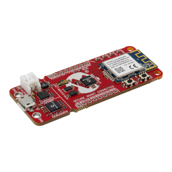
Page 3: Overview
AVR-IoT WA User Guide Overview Overview The AVR-IoT WA Board AVR-Io T WG De ve lo pme nt Bo ard Pino ut The AVR-IoT WA Development Board is shown in AVR-IoT Development Board. Figure 1-1. AVR-IoT Development Board Charg e S tatus LEDs... -
Page 4: Switch Button Use Cases
Indicates an error in the application. Switch Button Use Cases The AVR-IoT WA board also has two switches that can be used to enter modes at power-up: • Hold SW0 for two LED cycles to enter Soft AP mode (refer to Section 2.3.3 Via Soft... -
Page 5: Getting Started
Connecting the Board to the Host PC The AVR-IoT WA development board can be connected to a computer using a standard Micro-USB cable. Once plugged in, the LED array at the top right-hand corner of the board should flash twice in the following order: Blue, Green, Yellow, and Red. -
Page 6: Connecting The Board To Wi-Fi Networks
Via AVR-IoT Web Page There are several ways to connect the AVR-IoT WA Development Board to the Internet. The easiest way is through the AVR-IoT web page (www.avr-iot.com/aws). The lower left-hand corner of the site will show a wireless network connection window where the user can choose to connect to an open (no password required) network or enter the credentials for a password protected (WPA/WPA2/WEP) Wi-Fi network. - Page 7 • The AVR-IoT WA Development Board supports only 2.4 GHz networks inline, thus it is recommended to use mobile hotspots to connect the board to the Internet. Figure 2-4. Entering Wi-Fi Credentials in AVR-IoT Web Page Once the required details are entered, click the Download Configuration button.
- Page 8 AVR-IoT WA User Guide Getting Started Figure 2-5. Wi-Fi Configuration via Serial Command Line (Open Network) Figure 2-6. Wi-Fi Configuration via Serial Command Line (Secured Network) 2.3.3 Via Soft AP The last method to connect to the Wi-Fi is through the advanced Software Access Point (Soft AP) mode, a feature of the WINC module on board.
-
Page 9: Visualizing Cloud Data In Real Time
Out of the box, all AVR-IoT WA Development Boards are pre-registered to Microchip’s AWS Cloud sandbox account. This account is set up for demonstration purposes only. All data gathered by the sensors of the AVR-IoT WA Development Boards are published on the Microchip sandbox account and can be identified by the following details: Table 2-1. Project Details... - Page 10 AVR-IoT WA User Guide Getting Started sensors. The frequency of sending a PUBLISH packet can be decided by the user application. The application is written such that the sensor data is published to the Cloud every second. 2.4.1.1 Updating the Device Shadow In order to control the device from the Cloud, the AWS Shadow Service feature is used.
- Page 11 AVR-IoT WA User Guide Getting Started The device subscribes to ‘$aws/things/thingName/shadow/update/delta’.The shadow service will send updates on this topic when there is a difference in attribute values. For example, the reported toggle state is 1 but a client sent a desired state for toggle as 0. The device would receive update like below: "version": 1349,...
- Page 12 AVR-IoT WA User Guide Getting Started Figure 2-8. Illustration of AWS Shadow Service Publish-Subscribe Model 2.4.3 Sending the Messages The AVR-IoT web page displays a section called What's Next, two sections below the Light and Temperature graphs. In this section, the user can go through the steps of building their own custom application. To quickly preview the capability to send messages from the Cloud to the board, click the Implement a Cloud-Controlled Actuator ( icon, and then click the Learn More button to expand the section.
- Page 13 Viewing Messages Received on Subscribed Topic The toggle switch value corresponds to a short forced ON/OFF state to the yellow LED on the AVR-IoT WA Development Board. The LED will stay on/off for a short time depending on the position of the toggle switch before it...
-
Page 14: Configuring Other Settings
Microchip sandbox and migrated to a private account. Configuring Other Settings While the AVR-IoT WA Development Board comes fully programmed and provisioned right out of the box, the user can still control aspects of the application firmware behavior through the USB interface. There are three methods to do this: Hex file (reprogram) or WIFI.CFG (reconfigure credentials) drag and drop using the mass storage feature. - Page 15 AVR-IoT WA User Guide Getting Started Table 2-3. Serial Command Line Commands Command Arguments Description reset — Reset the settings on the device device — Print the unique device ID of the on-board ECC device thing — Print the unique thing name of the board reconnect —...
-
Page 16: Migrating To A Private Aws Cloud Account
Migrating to a Private AWS Cloud Account Once the features and capabilities of the AVR-IoT WA board have been explored, the user can begin the process to move development out of the MCHP sandbox environment and into a private AWS Cloud. In MCC, under the settings for the AVR-IoT AWS Sensor Node Library, tick the Use custom endpoint URL check box and fill in the AWS cloud details. -
Page 17: Code Source Platforms
Code Generation from MCC ® The source code of the AVR-IoT WA development board demo program is available for generation via the MPLAB Code Configurator (MCC) plugin in MPLAB X IDE. To generate the code, the following software and the appropriate versions should be installed. - Page 18 AVR-IoT WA User Guide Code Source Platforms Figure 3-1. Create New Project Figure 3-2. Selecting a Device ATmega4808 User Guide DS50002998A-page 18 © 2020 Microchip Technology Inc.
- Page 19 AVR-IoT WA User Guide Code Source Platforms Figure 3-3. Selecting a Programmer Figure 3-4. Selecting a Compiler User Guide DS50002998A-page 19 © 2020 Microchip Technology Inc.
- Page 20 AVR-IoT WA User Guide Code Source Platforms Figure 3-5. Naming a New Project Figure 3-6. MCC Start Page 3.1.1.2 Configuring the Settings of the Project The example module makes use of multiple libraries and peripherals. To configure the libraries, double click on each library in the Device Resources window to view their setup windows.
- Page 21 AVR-IoT WA User Guide Code Source Platforms Figure 3-7. AVR-IoT Peripheral Libraries Figure 3-8. AVR-IoT AWS Sensor Node Library Configuration 3.1.1.3 Component Libraries and Peripherals Important: Launching MCC v3.95 or earlier will automatically install an obsolete deprecated version of the AVR-IoT WG library. To avoid using this outdated library and its components, always check that you are loading the AVR-IoT AWS Sensor Node Library and not the "AVR-IoT WG Sensor Node"...
- Page 22 CrypthoAuthLib – The Crypto Authentication Library (CryptoAuthLib) shows the settings needed to configure the on-board ECC608 chip that provides the security features of the AVR-IoT WA board to work. It also indicates the communication settings between the ECC608 chip and the embedded microcontroller on board, as shown in CryptoAuthLib MCC.
- Page 23 AVR-IoT WA User Guide Code Source Platforms Figure 3-10. WINC MCC User Guide DS50002998A-page 23 © 2020 Microchip Technology Inc.
- Page 24 AVR-IoT WA User Guide Code Source Platforms Figure 3-11. MQTT MCC 3.1.1.4 Generating MCC Files and Programming the Board • After the addition and/or configuration of component libraries and peripherals, click the Generate button on the left-hand corner of the window, as shown in the Generating MCC Code, and wait for the generation to complete.
-
Page 25: Getting The Source Code From Github
Getting the Source Code from GitHub The source code for the AVR-IoT WA development board can also be downloaded from GitHub. There are different versions of the source code for MPLAB X and Atmel Studio. The hex file is also available for download from the releases tab for drag-and-drop programming. -
Page 26: Hardware Guide
Hardware Guide Hardware Guide The AVR-IoT WG and AVR-IoT WA boards, collectively referred to as the AVR-IoT Wx boards, share the same hardware components, configuration, and schematics. For in-depth information on the hardware features of the AVR- IoT Wx boards, see the full AVR-IoT Wx Hardware User Guide. -
Page 27: Faqs, Tips, And Troubleshooting
4. The user scanned the bar code with the phone/tablet, but nothing happened? Ensure the scanning of the QR code present on the sticker under the AVR-IoT WA board. It can be recognized by the distinguishing squares on the three of its corners and its proximity (same sticker) to the MCHP and Amazon logos (in color). -
Page 28: Led Status Troubleshooting
AVR-IoT WA User Guide FAQs, Tips, and Troubleshooting do no use WEP nor OPEN.) This Wi-Fi configuration is the factory default for all boards, so it will minimize the effort for first-time users. If preparing for a (medium/large) classroom demo, the user should set up a proper Wi-Fi router (2.4 GHz) instead. - Page 29 AVR-IoT WA User Guide FAQs, Tips, and Troubleshooting ...continued LED Sequence Description Diagnosis Action Blue LED is ON, Green Board is not connected to • Verify MQTT required LED is BLINKING the AWS Cloud Servers ports • Verify project credentials •...
-
Page 30: Relevant Links
Find schematics, design files, and ProductDetails.aspx?PartNO=EV15R70A purchase the board. Set up for Amazon Web Services AVR-IoT WA on www.microchipdirect.com/ProductSearch.aspx? Purchase the AVR-IoT WA board MCHPDirect Keywords=EV15R70A on Microchip Direct AVR-IoT Wx Hardware microchip.com/DS50002805 Find more information on the User Guide hardware of the AVR-IoT Wx boards. - Page 31 AVR-IoT WA User Guide Relevant Links Table 6-2. Related Tools and Resources Description MPLAB X IDE www.microchip.com/mplab/ Free IDE to develop applications for Microchip mplab-x-ide microcontrollers and digital signal controllers. Atmel Studio www.microchip.com/ Free IDE for the development of C/C++ and assembler code development-tools/atmel- for microcontrollers.
-
Page 32: Revision History
AVR-IoT WA User Guide Revision History Revision History Doc Rev. Date Comments 06/2020 Initial document release. User Guide DS50002998A-page 32 © 2020 Microchip Technology Inc. -
Page 33: The Microchip Website
AVR-IoT WA User Guide The Microchip Website Microchip provides online support via our website at www.microchip.com/. This website is used to make files and information easily available to customers. Some of the content available includes: • Product Support – Data sheets and errata, application notes and sample programs, design resources, user’s guides and hardware support documents, latest software releases and archived software •... -
Page 34: Trademarks
The Adaptec logo, Frequency on Demand, Silicon Storage Technology, and Symmcom are registered trademarks of Microchip Technology Inc. in other countries. GestIC is a registered trademark of Microchip Technology Germany II GmbH & Co. KG, a subsidiary of Microchip Technology Inc., in other countries. -
Page 35: Worldwide Sales And Service
New York, NY Tel: 46-31-704-60-40 Tel: 631-435-6000 Sweden - Stockholm San Jose, CA Tel: 46-8-5090-4654 Tel: 408-735-9110 UK - Wokingham Tel: 408-436-4270 Tel: 44-118-921-5800 Canada - Toronto Fax: 44-118-921-5820 Tel: 905-695-1980 Fax: 905-695-2078 User Guide DS50002998A-page 35 © 2020 Microchip Technology Inc.
Need help?
Do you have a question about the AVR-IoT WA and is the answer not in the manual?
Questions and answers