Table of Contents
Advertisement
Quick Links
AVR-IoT WG Development Board User Guide
Preface
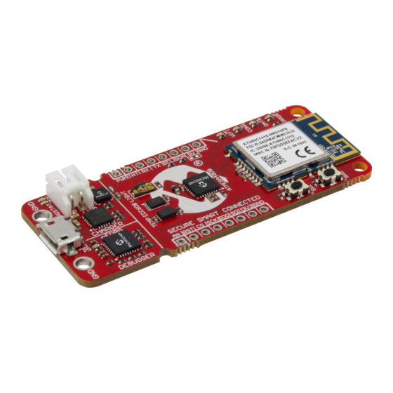
The AVR-IoT WG development board is a small and easily expandable demonstration and development
platform for IoT solutions, based on the AVR
designed to demonstrate that the design of a typical IoT application can be simplified by partitioning the
problem into three blocks:
•
Smart - represented by the ATmega4808 microcontroller
•
Secure - represented by the ATECC608A secure element
•
Connected - represented by the WINC1510 Wi-Fi controller module
The AVR-IoT WG development board features a USB interface chip Nano Embedded Debugger (nEDBG)
that provides access to a serial port interface (serial to USB bridge), a mass storage interface for easy
'drag and drop' programming, configuration and full access to the AVR microcontroller UPDI interface for
programming and debugging directly from Microchip MPLAB
AVR-IoT WG development board comes preprogrammed and configured for demonstrating connectivity
to the Google Cloud IoT Core.
The AVR-IoT WG development board features two sensors:
•
A light sensor
•
A high-accuracy temperature sensor - MCP9808
Additionally, a mikroBUS
actuators offered by MikroElektronika (www.mikroe.com) via a growing portfolio of Click boards
©
2018 Microchip Technology Inc.
AVR-IoT WG User Guide
®
microcontroller architecture using Wi-Fi
™
connector is provided to expand the board capabilities with 450+ sensors and
®
X IDE and the Atmel
User Guide
®
technology. It was
®
Studio 7.0 IDE. The
™
.
DS50002809A-page 1
Advertisement
Table of Contents

Related Manuals for Microchip Technology AVR-IoT WG


Summary of Contents for Microchip Technology AVR-IoT WG
-
Page 1: Preface
AVR-IoT WG User Guide AVR-IoT WG Development Board User Guide Preface The AVR-IoT WG development board is a small and easily expandable demonstration and development ® ® platform for IoT solutions, based on the AVR microcontroller architecture using Wi-Fi technology. It was... -
Page 2: Table Of Contents
AVR-IoT WG User Guide Table of Contents Preface..........................1 1. Chapter 1: Overview....................3 1.1. Board Layout..........................3 1.2. LED Indicators..........................3 2. Chapter 2: Getting Started..................4 2.1. Connecting the board to the PC....................4 2.2. AVR-IoT Development on START....................10 2.3. -
Page 3: Chapter 1: Overview
Chapter 1: Overview Chapter 1: Overview Board Layout The AVR-IoT WG development board layout can be seen below. LED Indicators The development board features four LEDs that the demo code uses to provide diagnostic information as represented in the table below. -
Page 4: Chapter 2: Getting Started
Connecting the board to the PC First, connect the AVR-IoT WG development board to the computer using a standard micro-USB cable. Once plugged in, the LED array at the top right-hand corner of the board should flash in the following order twice: Blue->Green->Yellow->Red. - Page 5 AVR-IoT WG User Guide Chapter 2: Getting Started the Yellow LED on the board. If there is no data streaming, the lower right-hand side of the page will be showing the video demonstration of the setup instructions. Figure 2-2. Webpage Status Indicators...
- Page 6 AVR-IoT WG User Guide Chapter 2: Getting Started Figure 2-3. AVR-IoT WG Webpage (No Wi-Fi Connection) 2.1.2 Connecting to the Wi-Fi Network When the connection has not been established, the lower left-hand corner of the Microsite will show a wireless network connection window where the user can enter the credentials for the Wi-Fi network. For...
- Page 7 2.1.3 Security Provisions The secure element (ATECC608A), present on the AVR-IoT WG boards, comes pre-registered within the MCHP AVR-IoT (sandbox) account on Google Cloud. Each secure element provides an 18-digit hexadecimal Unique Identification Number (UID) and a public or private key pair, pre-generated using Elliptic Curve cryptography.
- Page 8 2.1.5 The USB Interface While the AVR-IoT WG development board comes out of the box fully programmed and provisioned, the user can still access the firmware through the USB interface. There are three methods to do this: through User Guide DS50002809A-page 8 ©...
- Page 9 .hex file for each project it builds. This .hex file contains the code of the project. The AVR-IoT WG board facilitates putting code into the board by having this drag and drop feature. This feature does not require any USB driver to be installed and works in all major OS environments.
-
Page 10: Avr-Iot Development On Start
AVR-IoT WG User Guide Chapter 2: Getting Started WPA/WPA2 Figure 2-7. Serial Command Line Interface Figure 2-8. Wi-Fi Authentication Example III. USB Programmer/Debugger interface For users familiar with the Atmel Studio interface, the AVR microcontroller can also be programmed and debugged directly via the Atmel Studio 7.0 IDE. The AVR-IoT development board is automatically detected by the Atmel Studio IDE, enabling full programming and debugging through the on-board nEDBG interface. - Page 11 Click. To generate code for either of these, select the corresponding project in the examples list in Atmel START and follow steps 2 to 4 to regenerate the AVR-IoT WG development demo code. Additional code examples will be posted in future releases of the Atmel START tool.
- Page 12 AVR-IoT WG User Guide Chapter 2: Getting Started Figure 2-9. ATMEL START Homepage User Guide DS50002809A-page 12 © 2018 Microchip Technology Inc.
- Page 13 AVR-IoT WG User Guide Chapter 2: Getting Started Figure 2-10. ATMEL START Browse Examples Page User Guide DS50002809A-page 13 © 2018 Microchip Technology Inc.
- Page 14 AVR-IoT WG User Guide Chapter 2: Getting Started Figure 2-11. AVR-IoT WG Firmware Map User Guide DS50002809A-page 14 © 2018 Microchip Technology Inc.
- Page 15 AVR-IoT WG User Guide Chapter 2: Getting Started Figure 2-12. AVR-IoT WG Configuration Section User Guide DS50002809A-page 15 © 2018 Microchip Technology Inc.
-
Page 16: Advanced Modes
Switch 0 (SW0) and Switch 1 (SW1). Table 2-2 enumerates these advanced modes, descriptions, physical indicators of entering a specific mode, and how to enter them. Table 2-2. AVR-IoT WG Advanced Modes Advanced Mode Description Instructions... -
Page 17: Migrating To A Private Google Cloud Account
2.3.1 Soft AP Mode The AVR-IoT WG development board can be accessed through a Wi-Fi access point enabled by the Software-Enabled Access mode of the WINC1510. This can be another way to connect the board to a Wi-Fi network. To enter Soft AP mode, press and hold the SW0 push button before plugging the board. - Page 18 AVR-IoT WG User Guide Chapter 2: Getting Started Figure 2-15. Migrating to a Private Google Cloud Account User Guide DS50002809A-page 18 © 2018 Microchip Technology Inc.
-
Page 19: Chapter 3: Troubleshooting
AVR-IoT WG User Guide Chapter 3: Troubleshooting Chapter 3: Troubleshooting Table 3-1. Troubleshooting and Diagnostics LED Sequence Description Diagnosis Action ® Only Red LED is On Board is not connected Verify Wi-Fi credentials ® to Wi-Fi Blue and Red LEDs are Board is not connected •... -
Page 20: Appendix A: Hardware Components
AVR-IoT WG User Guide Appendix A: Hardware Components Appendix A: Hardware Components The AVR-IoT WG board features the following hardware components: • ATmega4808 Microcontroller • WINC1510 Wi-Fi Module • Light and Temperature Sensors • Four Light Emitting Diodes (1 each of Blue, Green, Yellow and Red) •... -
Page 21: Atecc608A
AVR-IoT WG User Guide Appendix A: Hardware Components Figure 4-2. WINC1510 ATECC608A ™ The ATECC608A is a secure element from the Microchip CryptoAuthentication portfolio with advanced Elliptic Curve Cryptography (ECC) capabilities. With ECDH and ECDSA being built right in, this device is... -
Page 22: Nedbg
ATmega4808 and provides an easy way to communicate with the target application through terminal software. It offers variable baud rate, parity, and Stop bit settings. The nEDBG controls one power and status LED on the AVR-IoT WG board. The table below shows how the LED is controlled in different operation modes. - Page 23 AVR-IoT WG User Guide Appendix A: Hardware Components ...continued Operation Mode Status LED Programming Activity indicator; the LED flashes slowly during programming/debugging with the nEDBG Fault The LED flashes fast if a power fault is detected. Sleep/Off LED is off. The nEDBG is either in Sleep mode or powered down.
-
Page 24: Appendix B: Board Layout
AVR-IoT WG User Guide Appendix B: Board Layout Appendix B: Board Layout Figure 5-1. AVR-IoT WG Development Board Layout User Guide DS50002809A-page 24 © 2018 Microchip Technology Inc. -
Page 25: Appendix C: Firmware Flowchart
AVR-IoT WG User Guide Appendix C: Firmware Flowchart Appendix C: Firmware Flowchart Figure 6-1. AVR-IoT WG Firmware Flowchart User Guide DS50002809A-page 25 © 2018 Microchip Technology Inc. -
Page 26: Appendix D: Relevant Links
Appendix D: Relevant Links Appendix D: Relevant Links The following list contains links to the most relevant documents and software for the AVR-IoT WG board. For those accessing the electronic version of this document, the underlined labels are clickable and will redirect to the appropriate website. -
Page 27: Document Revision History
AVR-IoT WG User Guide Document Revision History Document Revision History Doc. rev. Date Comment 09/2018 Initial document release. User Guide DS50002809A-page 27 © 2018 Microchip Technology Inc. -
Page 28: The Microchip Web Site
AVR-IoT WG User Guide The Microchip Web Site Microchip provides online support via our web site at http://www.microchip.com/. This web site is used as a means to make files and information easily available to customers. Accessible by using your favorite Internet browser, the web site contains the following information: •... -
Page 29: Product Identification System
AVR-IoT WG User Guide Product Identification System To order or obtain information, e.g., on pricing or delivery, refer to the factory or the listed sales office. PART NO. Device Tape and Reel Temperature Package Pattern Option Range Device: PIC16F18313, PIC16LF18313, PIC16F18323, PIC16LF18323... -
Page 30: Legal Notice
SQTP is a service mark of Microchip Technology Incorporated in the U.S.A. Silicon Storage Technology is a registered trademark of Microchip Technology Inc. in other countries. GestIC is a registered trademark of Microchip Technology Germany II GmbH & Co. KG, a subsidiary of Microchip Technology Inc., in other countries. -
Page 31: Quality Management System Certified By Dnv
AVR-IoT WG User Guide All other trademarks mentioned herein are property of their respective companies. © 2018, Microchip Technology Incorporated, Printed in the U.S.A., All Rights Reserved. ISBN: 978-1-5224-3574-7 AMBA, Arm, Arm7, Arm7TDMI, Arm9, Arm11, Artisan, big.LITTLE, Cordio, CoreLink, CoreSight, Cortex, DesignStart, DynamIQ, Jazelle, Keil, Mali, Mbed, Mbed Enabled, NEON, POP, RealView, SecurCore, Socrates, Thumb, TrustZone, ULINK, ULINK2, ULINK-ME, ULINK-PLUS, ULINKpro, µVision, Versatile... -
Page 32: Worldwide Sales And Service
New York, NY Sweden - Stockholm Tel: 631-435-6000 Tel: 46-8-5090-4654 San Jose, CA UK - Wokingham Tel: 408-735-9110 Tel: 44-118-921-5800 Tel: 408-436-4270 Fax: 44-118-921-5820 Canada - Toronto Tel: 905-695-1980 Fax: 905-695-2078 User Guide DS50002809A-page 32 © 2018 Microchip Technology Inc.
Need help?
Do you have a question about the AVR-IoT WG and is the answer not in the manual?
Questions and answers