
Subscribe to Our Youtube Channel
Related Manuals for CommScope ONECELL RP5200


Summary of Contents for CommScope ONECELL RP5200
- Page 1 ® ONECELL RP5200 Hardware Installation Guide Release 5.5 Document Number: M0304AG Document Revision: 5.5.01 Date: April 2021 DRAFT...
- Page 2 Copyright 2021 CommScope, All rights reserved. THIS DOCUMENT HAS BEEN DEVELOPED BY COMMSCOPE, AND IS INTENDED FOR THE USE OF ITS CUSTOMERS AND CUSTOMER SUPPORT PERSONNEL. THE SPECIFICATIONS AND INFORMATION REGARDING THE PRODUCTS IN THIS MANUAL ARE SUBJECT TO CHANGE WITHOUT NOTICE. ALL STATEMENTS, INFORMATION, AND RECOMMENDATIONS IN THIS MANUAL ARE BELIEVED TO BE ACCURATE BUT ARE PRESENTED WITHOUT WARRANTY OF ANY KIND, EXPRESS OR IMPLIED.
-
Page 3: Table Of Contents
Purpose......................... xi What you need to know ....................xi Customer documentation ..................... xi Conventions .......................xiii Notes, cautions, and warnings ................... xiv Chapter 1 CommScope ONECELL® overview Overview........................1-2 CommScope ONECELL system................1-2 ONECELL hardware components ................1-3 Baseband Controller physical ports..............1-3 Chapter 2 RP5200 installation RP5200 installation overview ..................2-2... - Page 4 Contents Appendix C Specifications Environmental and physical specifications............... C-1 SPF/SPF+ specifications................... C-2 Appendix D Cable installation and power separation guidelines Overview........................D-2 Cable handling ......................D-2 Cable termination......................D-3 Cable splicing .....................D-4 Cable termination ....................D-5 Cable grounding ....................D-10 Lightning protection....................D-12 Important guidelines..................D-12 Indoor box ......................D-12 Outdoor protection ...................D-13 Ceiling connector ....................D-15...
- Page 5 Contents ® ONECELL RP5200 Hardware Installation, Release 5.5...
- Page 6 List of figures Figure 1-1 ONECELL solution .................1-3 Figure 1-2 Baseband Controller ports ...............1-5 Figure 2-1 CommScope ceiling mount kit (CommScope PN ????)....2-3 Figure 2-2 Drop rail (CommScope PN ?????) ..........2-4 Figure D-1 Unreel cable ..................D-2 Figure D-2 Cable with sock attached using tie wrap.........D-3 Figure D-3 RJ45, IP67 connector..............D-3...
- Page 7 List of tables Table 1 Customer documentation ..............xii Table 2 Conventions ..................xiii Table 1-1 Baseband Controller physical port assignments.........1-4 Table A-1 RF exposure for ONECELL at maximum power internal antennas for RP5200 .................A-3 Table C-1 Environmental and Physical specifications........C-1 Table D-1 CAT-6A protection equipment parts list .........D-13 ®...
- Page 8 List of tables viii M0304AG 5.5.01 April 2021...
-
Page 9: Document Revision History
Document revision history ® The following section lists documentation changes in ONECELL RP5200 Installation Guide, v5.5 (M0304AG). Revision 5.5.01 (April 20, 2021) • Initial document release ® ONECELL RP5200 Hardware Installation, Release 5.5... - Page 10 Document revision history M0304AG 5.5.01 April 2021...
-
Page 11: About This Document
This document is written for computer hardware installers and administrators, network architects and business planners who are responsible for the planning and design of the CommScope ONECELL deployment environment. Purpose This guide provides the information necessary for installing the RP5200 hardware in the operator’s network. -
Page 12: Table 1 Customer Documentation
Contains a description of anchor features for the ® ONECELL Feature Guide, v5.5 current and previous releases, and a system overview, (M0304AE) including CommScope provided components and required components from other vendors. Describes main components of the ONECELL ® ONECELL Network Planning system, high-level view of hardware components, Guide, v5.5 (M0304AF) -
Page 13: Conventions
About this document Conventions This guide uses the following text conventions, as applicable. Table 2. Conventions Convention Description Syntax symbols < > Enclose a required parameter or set of parameters. For example: >band-class <class> is a required parameter. <class> Enclose an optional parameter or set of parameters. For example: >activate image <version>... -
Page 14: Notes, Cautions, And Warnings
About this document Table 2. Conventions Convention Description Indicates file names, directory paths, book titles, chapter Plain italic font titles, and user accounts. Bold font Indicates text that appears on screen exactly as shown, for example, names of screens, names of buttons, items on menus, and items on pull down lists. -
Page 15: Commscope Onecell® Overview
Chapter 1 ® CommScope ONECELL overview This chapter contains a high level overview of the ONECELL deployment and the ONECELL components installed in the ONECELL system. Overview CommScope ONECELL system ONECELL hardware components ® ONECELL RP5200 Hardware Installation, Release 5.5... -
Page 16: Commscope Onecell System
Chapter 1 CommScope ONECELL® overview Overview ONECELL is a revolutionary wireless system that can deliver the ultimate in wireless performance. • It eliminates cell borders and handovers • It can cover a large area with consistent user experience without any significant interference •... -
Page 17: Onecell Hardware Components
Chapter 1 CommScope ONECELL® overview Figure 1-1. ONECELL solution ONECELL hardware components The ONECELL hardware consists of the following components: • Baseband Controller — Baseband Controller Chassis — Baseband Controller Module — Power/Fan Unit (PFU) • Radio Points — RP2000 series —... -
Page 18: Table 1-1 Baseband Controller Physical Port Assignments
Chapter 1 CommScope ONECELL® overview Table 1-1. Baseband Controller physical port assignments Port Network Port Speed Media Type Description Assignment External Interface to access the WebGUI on the MGMT Local 1 Gbps RJ45 Management Baseband Controller. Not used 1 Gbps... -
Page 19: Figure 1-2 Baseband Controller Ports
Chapter 1 CommScope ONECELL® overview Figure 1-2. Baseband Controller ports Copper wire ports Fiber optic ports ® ONECELL RP5200 Hardware Installation, Release 5.5... - Page 20 Chapter 1 CommScope ONECELL® overview M0304AG 5.5.01 April 2021...
-
Page 21: Rp5200 Installation
Chapter 2 RP5200 installation This chapter describes installing RP5200 Radio Points on ceiling tiles, above ceiling tiles, on poles and in a flown configuration. RP5200 installation overview Ceiling mount ® ONECELL RP5200 Hardware Installation, Release 5.5... -
Page 22: Rp5200 Installation Overview
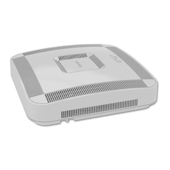
Chapter 2 RP5200 installation RP5200 installation overview The RP5200 is the Radio Point for indoor solutions. There are two configurations for installing the RP5200, which are dependent on the ceiling type. • Ceiling mount • Wall mount NOTE Once the Radio Point is installed and powered on, it may take up to 20 minutes for the frequency to stabilize and lock. -
Page 23: Ceiling Mount
CommScope: • Radio Point plate and screws • 4" octagon box, 1-1/2" deep with 1/2" side cutouts • Clamp and screw Figure 2-1. CommScope ceiling mount kit (CommScope PN ????) ® ONECELL RP5200 Hardware Installation, Release 5.5... -
Page 24: Figure 2-2 Drop Rail (Commscope Pn ?????)
Chapter 2 RP5200 installation Figure 2-2. Drop rail (CommScope PN ?????) Drop rail Clamp 2 screws M0304AG 5.5.01 April 2021... -
Page 25: Mounting The Radio Point On The Ceiling Tile
Chapter 2 RP5200 installation Mounting the Radio Point on the ceiling tile Remove two ceiling tiles from the overhead. Place the RP plate on the tile and mark the four holes on the tile. ® ONECELL RP5200 Hardware Installation, Release 5.5... - Page 26 Chapter 2 RP5200 installation Cut the opening according to the dimensions in the following drawing. Attach the octagon box to the ceiling bracket using a clamp and screw. Clamp Drop ceiling rail Octagon Screws M0304AG 5.5.01 April 2021...
- Page 27 Chapter 2 RP5200 installation Replace the ceiling tile with the cutout. Install the drop rail/octagon box assembly over the modified tile. ® ONECELL RP5200 Hardware Installation, Release 5.5...
- Page 28 Chapter 2 RP5200 installation Attach the mounting plate onto the octagon box on the RP side of the tile. Need drawing M0304AG 5.5.01 April 2021...
- Page 29 Chapter 2 RP5200 installation Attach base plate to the Radio Point. Install the blue and red Ethernet cables provided in the mounting kit on the RP as shown below. Is there a step for connecting the RP Ethernet cables to the switch Ethernet cables? 11 Attach the RP to the octagon plate.
- Page 30 Chapter 2 RP5200 installation Align the keyhole opening on the octagon mounting plate with the button on the RP mounting plate. b Lift the RP vertically and slide it into the locked position. Is this the correct location 12 Mount the Radio Point on the octagon box plate. for this step? Delete this this step 2-10...
- Page 31 Chapter 2 RP5200 installation Need drawing 13 Replace the ceiling tile next to the Radio Point. ® ONECELL RP5200 Hardware Installation, Release 5.5 2-11...
-
Page 32: Mounting The Radio Point Above The Ceiling Tile
Chapter 2 RP5200 installation Mounting the Radio Point above the ceiling tile Remove ceiling tile from the overhead. 2-12 M0304AG 5.5.01 April 2021... - Page 33 Chapter 2 RP5200 installation Attach the octagon box to the bracket. CommScope recommends an Eaton B-line – BA50A adjustable bracket. NOTE: Clamp Drop rail Octagon Screw ® ONECELL RP5200 Hardware Installation, Release 5.5 2-13...
- Page 34 Chapter 2 RP5200 installation Attach the bracket to the mounting plate to the octagon box. Need revised drawing Attach plate to the Radio Point. Install the blue and red Ethernet cables provided in the mounting kit on the RP as shown below.
- Page 35 Chapter 2 RP5200 installation Is there a step for connecting the RP Ethernet cables to the switch Ethernet cables? Attach the RP to the octagon plate. Align the keyhole opening on the octagon mounting plate with the button on the RP mounting plate. b Lift the RP vertically and slide it into the locked position.
- Page 36 Chapter 2 RP5200 installation Is this the correct location Mount the Radio Point on the octagon box plate. for this step? Need drawing 2-16 M0304AG 5.5.01 April 2021...
- Page 37 Chapter 2 RP5200 installation Install drop rail above the ceiling tile. Need revised drawing with new plates ® ONECELL RP5200 Hardware Installation, Release 5.5 2-17...
- Page 38 Chapter 2 RP5200 installation Need revised drawing 3” Ceiling tile Replace the ceiling tile next to the Radio Point. The minimum clearance NOTE: for cooling is 3 inches. 10 Replace the ceiling tile. 2-18 M0304AG 5.5.01 April 2021...
- Page 39 Chapter 2 RP5200 installation ® ONECELL RP5200 Hardware Installation, Release 5.5 2-19...
- Page 40 Chapter 2 RP5200 installation 2-20 M0304AG 5.5.01 April 2021...
-
Page 41: Safety
Appendix A Safety This appendix contains specifications for CommScope ONECELL, including FCC information and technical data. Radiation Exposure Statement Human exposure limits for ONECELL deployments FCC ID ® ONECELL RP5200 Hardware Installation, Release 5.5... -
Page 42: Radiation Exposure Statement
Chapter A Safety Radiation Exposure Statement Important: Changes or modifications not expressly approved by CommScope LLC could void your authority to operate the equipment. FCC Part 15 The Baseband Controller and RP5100 have been tested and found to comply with the limits for Class A equipment, pursuant to Part 15 of the FCC Rules. -
Page 43: Table A-1 Rf Exposure For Onecell At Maximum Power Internal Antennas For Rp5200
Chapter A Safety Table A-1 includes values for one RP5200 Radio Point and four Radio Points per chassis. Table A-1. RF exposure for ONECELL at maximum power internal antennas for RP5200 RPM-A5A11- RPM-A5A11- RPM-I5A11- RPM-I5A11- RPM-I5A11- Parameter Tx Power (dBm) per 24.13 24.23 24.25... -
Page 44: Reference Documents
Chapter A Safety RPM-I5A11- RPM-A5A11- RPM-A5A11- RPM-A5A11- RPM-A5A11- Parameter Transmitter Duty Cycle % Number of Antennas (MIMO) Contribution due to 3.0103 3.0103 3.0103 3.0103 3.0103 multiple antennas (dB) Derived Total EIRP (dBW) -1.290 -1.110 -1.540 -3.410 -1.000 Bands Frequency Range (MHz) 734-746 729 - 746 758 - 768... -
Page 45: Fcc Id
Chapter A Safety FCC ID The FCC ID is available on the information labels attached to the RPs. RP5200 For the RP5200, the FCC ID for each of the installed radio modules is visible when the cover is removed. The drawing below shows the label on the radio module. ®... - Page 46 Chapter A Safety M0304AG 5.5.01 April 2021...
-
Page 47: Installation Troubleshooting
Appendix B Installation troubleshooting This section contains information on troubleshooting the ONECELL installation. It includes the LED patterns for the Baseband Controller and Radio points. Radio Point RP5200 LED patterns ® ONECELL RP5200 Hardware Installation, Release 5.5... -
Page 48: Radio Point Rp5200 Led Patterns
Appendix B Installation troubleshooting Radio Point RP5200 LED patterns The Radio Point RP5200 supports six LEDs on the front cover. Indicators are for • four radios (one for each) • ETH 1 – MR PORT:POE++, POE+, Ethernet link • ETH 2– SR PORT:POE++, POE+, Ethernet link ETH 1, 2 RADIO 1, 2, 3, 4 The following table shows:... - Page 49 Appendix B Installation troubleshooting • Action to take, if any, to resolve the issue Display Pattern Indicates Action to Take RADIO 1 Green, solid Power On, transmitting None RADIO 2 Amber, solid • RFTxState OFF • Check 1588 VLAN configuration RADIO 3 •...
- Page 50 Appendix B Installation troubleshooting M0304AG 5.5.01 April 2021...
-
Page 51: Environmental And Physical Specifications
Appendix C Specifications This appendix contains specifications for CommScope ONECELL, including FCC information and technical data. Environmental and physical specifications SPF/SPF+ specifications Environmental and physical specifications The following table lists the electrical ratings and technical data for the RP5200. Table C-1. -
Page 52: Spf/Spf+ Specifications
Appendix C Specifications SPF/SPF+ specifications The following table lists the SPF and SPF+ specifications required for the Baseband Controller. 1G SFP LC SX Transceiver; 220M to 1K M 1G SFP LC LX transceiver, 550M 10K M 10G SFP+ LC SR Transceiver; Multi mode 26M to 300M SFP-10G-LR Transceiver;... - Page 53 Appendix D Cable installation and power separation guidelines This section contains best practices for installing Ethernet cables and connecting them to RPs. Overview Cable handling Cable termination Lightning protection D-12 Ceiling connector D-15 Patch panel D-17 Power separation guidelines D-17 ®...
-
Page 54: Overview
Unreel long lengths of cable to ensure the cable does not become twisted or caught on objects. Figure D-1. Unreel cable CommScope recommends using a sock fitted and secured over the plug to pull cable through long conduits. Sock information Tie wrap information M0304AG 5.5.01 April 2021... -
Page 55: Cable Termination
Appendix D Cable installation and power separation guidelines Figure D-2. Cable with sock attached using tie wrap Sock Conduit Tie-wrap Feed the sock through the conduit and secure the sock on the terminal end of the cable with the tie-wrap. Once the sock and tie-wrap are in place, pull the cable through the conduit. -
Page 56: Cable Splicing
Appendix D Cable installation and power separation guidelines Use the split grommet provided. Once it is in place, coat it with silicone to ensure the connector is sealed. Figure D-4. Assembling the connector on the RP end Cable splicing Some cables are run in one piece from source to destination and have connector terminations. -
Page 57: Cable Termination
Appendix D Cable installation and power separation guidelines Position the filled tube to overlap the end of the inner jacket and seal the gel. Clean off all excess sealant. Tape can be used to stabilize the tube for immediate termination before NOTE: the sealant sets. - Page 58 Appendix D Cable installation and power separation guidelines Pull back the jacket along the slit and remove. M0304AG 5.5.01 April 2021...
- Page 59 Appendix D Cable installation and power separation guidelines Fold back the foil shielding and drain wire to expose the inner jacket. Prepare the inner jacket for blocking the gel and direct burial. Cut back the inner jacket b Trim the flute Clean the excess gel The flute can be cut longer to match the blocking tube length.
- Page 60 Appendix D Cable installation and power separation guidelines Fill all space inside the tubing with B-sealant and position the filled tube to overlap the end of the inner jacket and seal the gel. Fold the drain wire and foil back over the tube and position the foil to be folded back over the tube.
- Page 61 Appendix D Cable installation and power separation guidelines An extra piece of foil can be used to cover the foil seam. For an HGS620 termination, wrap the drain wire at least two times around and position it where the spring clips will capture them. Tape over the foil for stability.
-
Page 62: Cable Grounding
Appendix D Cable installation and power separation guidelines Cable grounding For CAT-6A cables, the shield termination method is to use the ground lug and B- bond clip that are available in the 12A1 Grounding Kit. Fold the foil back over the jacket end and wrap the drain wire around the end and push the ground lug over the wrap. - Page 63 Appendix D Cable installation and power separation guidelines Open the B-bonding clip to be placed and closed over the grounding lug. The lug tail can be cut off or used for ground attachment. Treat the inner jacket as described in step 4 on page D-7.
-
Page 64: Lightning Protection
• Maintain pair twists up to termination points • Avoid having pairs crossing over each other Indoor box To protect the cables in an indoor installation from lightning damage, CommScope recommends using the ITW Linx CAT6-A-LAN protector. NOTE The gel filled outdoor cable types will still need blocking. See... -
Page 65: Outdoor Protection
Appendix D Cable installation and power separation guidelines Figure D-5. CAT6-A lightning protector Outdoor protection The following is an example of a pole mounted CAT-6A configuration for protecting remote equipment installed outdoors. Table D-1 lists the recommended parts for installing the protection equipment. Table D-1. -
Page 66: Figure D-6 Remote Equipment Protection For Outdoor Devices
Appendix D Cable installation and power separation guidelines Figure D-6. Remote equipment protection for outdoor devices NEMA 4x enclosure Back panel Bottom Mounted Liquid Tight Cordgrips Bottom Mounted Liquid Tight Bushing Ground Buss NOTE Enclosure should be mounted close to the equipment for the best protection. D-14 M0304AG 5.5.01 April 2021... -
Page 67: Figure D-7 Protector Box Mounted To Pole
If surge protection is not needed, gel flooded cables can be blocked and transitioned to indoor cable using a ceiling connector. The following link is for the recommended CommScope part. Ceiling connector Terminate the indoor cable first – then lay down a bed of B sealant. - Page 68 Appendix D Cable installation and power separation guidelines Clean all gel from the end of the OSP cable. After the cable and conductors are positioned, fill the area around the cable end with sealant and close the connector housing. D-16 M0304AG 5.5.01 April 2021...
-
Page 69: Patch Panel
Appendix D Cable installation and power separation guidelines Patch panel CommScope recommends installing a patch panel in the NOC to connect and manage CAT-6A cables. The following is a list of recommended CommScope 24 and 48 port patch panels and high density information outlets. •... - Page 70 Appendix D Cable installation and power separation guidelines D-18 M0304AG 5.5.01 April 2021...
- Page 71 ® ONECELL RP5200 Hardware Installation, Release 5.5...
- Page 72 DRAFT ® ONECELL RP5200 Hardware Installation, Release 5.5 M0304AG 5.5.01 April 2021...
Need help?
Do you have a question about the ONECELL RP5200 and is the answer not in the manual?
Questions and answers