
Related Manuals for EVA Stampaggi SB 80


Summary of Contents for EVA Stampaggi SB 80
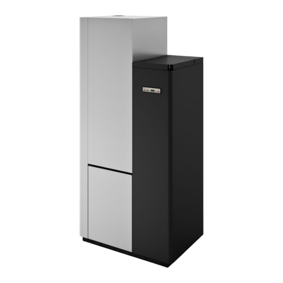
- Page 1 INSTRUCTION MANUAL PELLET STORAGE WATER HEATER PELLET THERMO- STOVE Models: SB 80 TEK 80...
- Page 2 IMPORTANT: PLEASE READ Eva Stampaggi S.r.l. assumes no responsibility for damage to persons and/or property or for the malfunction of the stove resulting from non-compliance with the provisions of this Instruction Manual The guarantee will remain valid for 1 year for professional operators and 2 years for consumers.
-
Page 3: Table Of Contents
TABLE OF CONTENTS PRODUCT SAFETY………………………………………………………………………………………………….………... p. 3 GENERAL SAFETY REGULATIONS……………………………………………………………………………………….. p. 3 PRODUCT DESCRIPTION……………………………………………………………………………………………………. p. 5 03.01 SB80/TEK 80…………………………………………………….……………………………………………………. p. 5 03.02 TECHNICAL DATA…………………………………………………………………………………………………… p. 5 MINIMUM INSTALLATION REQUIREMENTS…………………………………………………………………………….. p. 6 FLUE PIPE…………………………….………………………………………………………………………………………... p. 7 05.01 CHIMNEY……………………………………………………………………………………………………………… p. 8 05.02 DRAUGHT…………………………………………………………..……………………........p. 8 05.03 EFFICIENCY OF THE HYDRO/BOILER STOVE…………………………………………………………………. -
Page 4: Product Safety
Read this manual carefully before use or any maintenance operation. Eva Stampaggi aims to provide as much information as possible to ensure safer use and to avoid damage to persons, property or parts of the stove itself. Each stove is subjected to internal testing before shipment and, as such, residues inside the appliance may be found. - Page 5 • Do not modify the appliance without prior authorisation. • Use only original spare parts recommended by the manufacturer. • Make sure that the stove is transported in compliance with safety regulations. Avoid any improper transfers or knocks that may damage the ceramics or the structure.
-
Page 6: Product Description
03. PRODUCT DESCRIPTION 03.1 SB80 / TEK 80 TECHNICAL DRAWING 03.2 TECHNICAL DATA Technical data of the appliance: SB 80 / TEK 80 Dati tecnici dell’apparecchio: Name: Nominal heat Reduced output heat output Designazione: Potenza Potenza termica termica ridotta nominale Fuel throughput 2.42... -
Page 7: Minimum Installation Requirements
Eva Stampaggi S.r.l. assumes no criminal and/or civil liability, direct and/or indirect for the malfunction of the stove and for damage to persons or property caused by non-compliance with the requirements for installation of the stove and/or tampering with it. -
Page 8: Flue Pipe
05. FLUE PIPE FLUE PIPE SPECIFICATIONS SB 80 stoves have the following specifications: Chimney flue draught: 11 Pa Fume temperature: 230 °C Mass flow of fumes: 5.7 g/s Use a flue pipe and an anti-corrosion fume connection to the flue pipe. The temperature of the fumes and the pellet stove is very low. It could create condensation and corrode the fume exhaust. -
Page 9: Chimney
05.1 CHIMNEY COWL A properly installed chimney cowl ensures optimum stove operation. The anti-downdraught chimney cowl consists of a number of components whose outlet section sum always doubles the flue pipe section. Make sure the chimney cowl is at least 150cm above the roof rise so that it is fully exposed to the wind. - Page 10 By using coaxial tubes, the air will be pre-warmed contributing to improved combustion and lower emissions into the atmosphere. Before installing, the following indications must be met: Select the position where the stove is to be installed and: • Arrange the connection to the flue pipe for fume extraction. Arrange the external air intake (combustion air).
- Page 11 EXAMPLES OF INSTALLATION: EXAMPLES OF INCORRECT INSTALLATION: Outdoor air intake Outdoor air intake with non-resealable grid with non-resealable grid Exhaust pipes must never be fitted pointing downwards or horizontally so that fumes are discharged directly through the external wall.
-
Page 12: Connection/System Schematics
06.1 CONNECTION/SYSTEM SCHEMATICS STORAGE WATER HEATER MODE THERMO-STOVE MODE... -
Page 13: Installation
07. INSTALLATION HANDLING AND UNPACKING When transporting do not position the product horizontally. Unloading of the product must be performed using lifting means that are suitable and that have characteristics that are consistent with the weight of the stove. The operator must make sure that during offloading and lifting of the stove there are no persons or objects nearby. -
Page 14: Hydraulic Connection
07.1 HYDRAULIC CONNECTION CAUTION: THE FOLLOWING ARE NOT PROVIDED WITH THE ITEM: AUTOMATIC BLOW VALVE, SAFETY VALVE, ELECTRONIC PRESSURE SENSOR, or EXPANSION TANK. • Specifications of the pump to be installed: Electronic pump with a head of at least 6 metres. •... - Page 15 INSTALLATION INSTRUCTIONS STORAGE WATER HEATER MODE INSTALLATION Remove the 2 covers for the installation of the system pipes and the fume duct. The fume duct must be certified according to EN1856-2. The use of flexible tubing is recommended to connect the appliance to the hydraulic system as, in the case of routine or non-routine maintenance, this will make it easier to move.
-
Page 16: Electrical Connection
07.2 ELECTRICAL CONNECTION The electrical connection must be performed by qualified personnel who install circuit breakers upstream of the appliance. Particular attention must be paid when the stove is an integration to the system and all the equipment must operate as planned. Avoid installations with electric cables that run close to fume pipes or hot components that are suitably insulated. -
Page 17: Electronics With N.100 3 Button Led Display
08. ELECTRONICS WITH N.100 3 BUTTON LED DISPLAY 08.1 CONSOLE Console The control panel shows the information concerning the stove status. Several types of data can be displayed and the settings available according to the access level can be modified by entering the menu. A display and the LED indicators inform about the stove operational status. Depending on the operating mode, the displays may take on different meanings depending on their position on the display. -
Page 18: User Functions
Menu M6 – LOAD INITIAL This command is only available when the stove is OFF and allows the auger tube to be loaded the first time the stove is started when the pellet hopper is empty. After selecting the INITIAL LOAD menu, “Press more” will scroll on the display. Then press P2 (increase). The exhaust blower switches on at the maximum speed and the auger tube (auger tube LED on) starts working. -
Page 19: Alarms
The display shows “GO-STBY”. At the end of a preset time, the display shows the message “UAIT COOLING”. When the fume temperature reaches the threshold set by the Pr13 parameter, the stove goes into STAND-BY mode and the message “STOP ECO TEMP GOOD” scrolls on the display. If the boiler temperature falls below the set temperature minus the threshold given by the preset delta, the stove will restart. -
Page 20: Connections
General thermostat alarm In the event that the safety thermostat detects a temperature higher than the trigger threshold, it will intervene to disconnect the auger (which is simultaneously fed and in series). The message SAFETY THERMAL is displayed and the system is shut down. Unscrew the black cap near the pellet hopper cover and press the button to reset the contact. -
Page 21: Cleaning And Routine Maintenance
Eva Stampaggi S.r.l. assumes no criminal and/or civil liability, direct and/or indirect for the malfunction of the stove and for damage to persons or property caused by the failure/incorrect cleaning and routine maintenance of the stove. -
Page 22: Troubleshooting
12. TROUBLESHOOTING PROBLEM CAUSE SOLUTION IT MAY BE NECESSARY TO REPEAT THE FIRST LOAD PHASE A FEW TIMES TO FACILITATE THE APPLIANCE INITIAL FIRST START-UP START-UP AS THE AUGER TUBE IS COMPLETELY EMPTY AND IT MAY TAKE A SPECIFIC PERIOD OF TIME TO FILL. POWER OUTAGE CHECK PLUG AND POWER SUPPLY. - Page 23 ALAR FUME PROBE FAULTY FUME SENSOR CALL TECHNICAL SUPPORT. FUME PROBE ACTIVE ALARM AL2 FUME PROBE FUME SENSOR DISCONNECTED CALL TECHNICAL SUPPORT. AL. FUME P. FAULTY FUME SENSOR CALL TECHNICAL SUPPORT. ALAR HOT TEMP FAULTY CONTROL BOARD CALL TECHNICAL SUPPORT. HOT SMOKE ACTIVE ALARM FAULTY EXCHANGER BLOWER CALL TECHNICAL SUPPORT.
-
Page 24: Annual Scheduled Maintenance
13. YEARLY SCHEDULED MAINTENANCE Date 1st maintenance ____________ / ____________ / (Technical Assistance Centre stamp) Date 2nd maintenance ____________ / ____________ / (Technical Assistance Centre stamp) Date 3rd maintenance ____________ / ____________ / (Technical Assistance Centre stamp) 10. CERTIFIES... -
Page 25: Installation And Test Certification
14. CERTIFICATE OF INSTALLATION AND TESTING CERTIFICATE OF INSTALLATION AND TESTING CUSTOMER: _______________________________________ Dealer Stamp: STREET/ROAD: ____________________________________________ CITY: _________________________________________ Installer stamp: POSTAL CODE: ___________________________________________ PROVINCE: _____________________________________ TEL: ____________________________________________ First name: ___________________________________________ Delivery date: _________________________________ Last Name: ________________________________________ Delivery date: ____________________________ Address: ______________________Post Code:__________ Equipment mod.: _________________________________ Location: _________________________________________... -
Page 26: Warranty
Eva Stampaggi S.r.l. guarantees that the stove is free from defects that make it unsuitable for its intended use or significantly reduce its value. The rules of the Italian Civil Code or applicable national law governing the guarantee in the sales contract, or applicable national law ex D. Int. - Page 27 Proper waste disposal is important not only for the environment and the health of citizens, but also because this operation leads to a recovery of materials that have significant energy and resource savings. Eva Stampaggi S.r.l. Dealer Stamp and Signature Via Cal Longa Z.I.
- Page 28 Tel: +39 0438 740433 Fax: +39 0438 740821 I dati e le caratteristiche indicate non impegnano Eva Stampaggi S.r.l., che si riserva il diritto di apportare le modifiche ritenute opportune senza obbligo di preavviso o di sostituzione. Tutti i diritti riservati. Vietata riproduzione totale o parziale senza espressa autorizzazione di Eva Stampaggi S.r.l.
Need help?
Do you have a question about the SB 80 and is the answer not in the manual?
Questions and answers