Table of Contents
Advertisement
Quick Links
Advertisement
Table of Contents

Related Manuals for EVA Stampaggi NINA


Summary of Contents for EVA Stampaggi NINA
- Page 1 INSTRUCTION MANUAL PELLET STOVES PELLET STOVE...
- Page 2 IMPORTANT: ESSENTIAL TO READ 1. The warranty is only valid if the INITIAL IGNITION is carried out by an AUTHORISED TECHNICIAN. 2. Do not turn the product UPSIDE DOWN or LAY IT IN A HORIZONTAL POSITION DURING TRANSPORTATION AND INSTALLATION.. 3.
- Page 4 9. The burn pot and the combustion chamber MUST BE CLEANED DAILY. The manufacturer declines any liability for any malfunctioning due to a failure to do so. Eva Stampaggi S.r.l. declines any liability for any damage to persons or property arising from the failure to comply with the points mentioned...
-
Page 5: Table Of Contents
INDICE 01. PRODUCT SAFETY ......................... 5 01.1 SAFETY WARNINGS ....................5 01.2 GENERAL SAFETY PRECAUTIONS ................6 01.3 E CERTIFICATE OF CONFORMITY ................8 02. PRODUCT DESCRIPTION ....................... 9 02.1 DESCRIPTION OF COMPONENTS ................10 03. INSTALLING THE PRODUCT ....................11 03.1 INTRODUCTION .................... -
Page 6: Product Safety
Read this manual carefully before use or any maintenance operation. Eva Stampaggi aims to provide as much information as possible to ensure safer use and to avoid damage to persons, property or parts of the stove itself. -
Page 7: General Safety Precautions
01. PRODUCT SAFETY 01.2 GENERAL SAFETY PRECAUTIONS Use the stove only as described in this manual. Any other use not recommended by the manufacturer may cause fires or accidents to people. Make sure that the electrical power available corresponds to the value indicated in the data plate (220V~/50Hz). ... - Page 8 01. PRODUCT SAFETY Do not use the appliance as waste incinerator or for any other purpose other than the intended one. Do not use liquid fuels. Do not modify the appliance without prior authorisation. Use only original spare parts recommended by the manufacturer. ...
-
Page 9: E Certificate Of Conformity
01. PRODUCT SAFETY 01.3 EC CERTIFICATE OF CONFORMTY... -
Page 10: Product Description
02. PRODUCT DESCRIPTION Pellet stoves This type of stove combines the convenience of pellets with the proven tradition of an economic kitchen with which it is possible to prepare meals and heat the environment at the same time. Thanks to technology, in this case also not only is it possible to cook but the appliance was created to provide plenty of space to do so. -
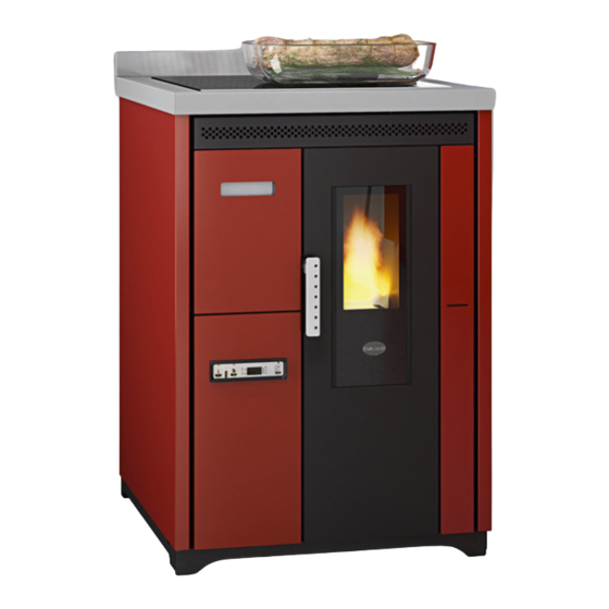
Page 11: Description Of Components
02. PRODUCT DESCRIPTION 02.1 DESCRIPTION OF COMPONENTS DOOR PELLET DRAWER HANDLE DISPLAY STEEL or GLASS CERAMIC PLATE VENTILATED AIR OUTLET SAFETY THERMOSTAT RS 232 ON/OFF SWITCH... -
Page 12: Installing The Product
INSTALLATION WITH WALL FUME OUTLET IS PROHIBITED. INSTEAD THE FUME OUTLET MUST BE ROOF-TYPE AS PROVIDED FOR BY NATIONAL REGULATIONS. Eva Stampaggi S.r.l. declines any liability for any damage to persons or property arising from the failure to comply with the points mentioned above and from non-compliant product installation. - Page 13 03. INSTALLING THE PRODUCT The vent pipe is one of the key features for guaranteeing the proper functioning of the stove. Thanks to the quality of the materials, the strength, the durability, the easy cleaning and maintenance, the best vent pipes are made of steel, either stainless steel or aluminised.
- Page 14 03. INSTALLING THE PRODUCT EXISTING VENT PIPE (TRADITIONAL) Types of vent pipe: Examples of vent pipe Steel vent pipe with Traditional clay vent pipe double chamber with cavities. Optimal insulated with material efficiency. resistant 400°C. Optimum efficiency. Avoid vent pipes with Refractory vent pipe with insulated double chamber internal...
-
Page 15: Chimney Cowl
03. INSTALLING THE PRODUCT 03.3 CHIMNEY COWL A properly installed chimney cowl ensures optimum stove functioning. The anti-downdraught chimney cowl consists of a number of components whose outlet section sum always doubles the vent pipe section. Make sure the chimney cowl is at least 150cm above the roof top so that it is fully exposed to the wind. -
Page 16: Draught
03. INSTALLING THE PRODUCT 03.4 DRAUGHT Fumes heat up during combustion, increasing their volume. Their density is therefore lower than the one of the surrounding colder air. This difference between the inside and outside temperatures of the chimney results in a negative pressure which increases proportionally to the vent pipe length and the temperature. -
Page 17: Stove Efficiency
03. INSTALLING THE PRODUCT 03.5 STOVE EFFICIENCY Highly efficient stoves may pose difficulties for fume extraction. In order for a vent pipe to work properly its internal temperature must increase as a consequence of the fumes generated during combustion. Importantly, the efficiency of a heater is determined by its ability to transfer most of the heat produced to the environment to be heated: consequently, the greater the efficiency of the stove, the "colder"... -
Page 18: Installation
03. INSTALLING THE PRODUCT 03.6 INSTALLATION Using coaxial tubes the air will be pre-warmed contributing to improved combustion and lower emissions into the atmosphere. Follow the instructions below before installing your stove. Select the position where the stove is to be installed and: ... - Page 19 03. INSTALLING THE PRODUCT The combustion air intake must be connected directly to the outside or to adjacent rooms provided they are fitted with external air supply vents and are not used as bedrooms or bathrooms or, whenever a fire hazard exists, as storage rooms, garages, combustible material warehouses, etc.
- Page 20 03. INSTALLING THE PRODUCT INSTALLATION EXAMPLE: EXAMPLE OF INCORRECT INSTALLATION: Exhaust pipes must never be fitted pointing downwards or horizontally so that fumes are discharged directly through the external wall.
- Page 21 03. INSTALLING THE PRODUCT INSTALLATION Before installing the stove rotate the rear upstand (if any), by loosening the screws. To install the stove with rear exhaust, it is necessary to break the semi-cut on the rear and then install the pipes. In compliance with the current regulations for installation, the pellet stove must be installed in a ventilated place with air that is sufficient to ensure correct combustion and therefore good operation.
- Page 22 03. INSTALLING THE PRODUCT ATTENTION: The pellet stove must be fitted with a 0.5 m-long pipe (Φ 80 mm) certified to EN 1856-2 standard. The pellet stove, depending on the model you have purchased, can be installed flush or with free-standing installation. In the case of free-standing installation respect the following distances from combustible wall: side: 20 cm FREE-STANDING INSTALLATION rear: 1 cm FREE-STANDING INSTALLATION...
-
Page 23: Product Use
04. PRODUCT USE 04.1 ELECTRONICS WITH 3-BUTTON DISPLAY Proper functioning and control adjustment devices Console The control board can be managed by simply pressing a few buttons on the control panel. A display and the LED indicators inform about the stove operational status. When in programming mode all the parameters that can be modified using the buttons are shown on the display. - Page 24 04. PRODUCT USE The menu Hold P1 button down to access the menu. It includes several items and levels to access settings and control board programming. User menu The table below briefly describes the menu structure, focusing in particular on the functions available to users. level 1 level 2 level 3...
- Page 25 04. PRODUCT USE M2-4 – weekend programming 01 – weekend chrono on/off 02 - start weekend 1 OFF-0-23:50 03 - stop weekend 1 OFF-0-23:50 04 - start weekend 2 OFF-0-23:50 05 - stop weekend 2 OFF-0-23:50 M2-5 - exit M3 – select language 01 –...
- Page 26 04. PRODUCT USE Select the desired day and press P3 button (figure 13b). Then set the hour (figure 13c), minutes (figure 13d), day (figure 13e), month (figure 13f) and year (figure 13g) by pressing P1 (decrease) and P2 (increase) buttons. Press P3 button to confirm the desired value.
- Page 27 04. PRODUCT USE Menu M02 - time clock setting Sub-menu M2 - 1 – Enable chrono All programmable thermostat functions can be disabled and enabled by means of the menu that appears on the display "M2 set chrono” (M2 chrono set). Press P3 button and then P1 or P2, for selecting On or Off respectively, to enable the programmable thermostat. Press P3 button to confirm.
- Page 28 04. PRODUCT USE PROGRAMME 1 menu level setting meaning available values M2-3-02 START PRG 1 switching-on time OFF-0-23:50 M2-3-03 STOP PRG 1 switching-off time OFF-0-23:50 M2-3-04 MONDAY PRG 1 on/off M2-3-05 TUESDAY PRG 1 on/off M2-3-06 WEDNESDAY PRG 1 on/off M2-3-07 THURSDAY PRG 1 on/off...
- Page 29 04. PRODUCT USE Sub-menu M2 - 4 – weekend programming The programmable thermostat functions can be enabled/disabled and set for the weekend (days 6 and 7, or Saturday and Sunday). Select “chrono weekend” (weekend chrono) item and press P3 button to enable it. Then select “on” using P1 (decrease) or P2 (increase) button. Set Start 1 fine - sett and Stop 1 fine –...
- Page 30 04. PRODUCT USE Menu M06 – first load This function is only available when the stove is switched OFF. It allows the auger tube to be loaded upon the first stove start-up when the pellet hopper is empty. After selecting menu M6, the message "Pressure inc" (figure 18a) will scroll on the display. Then press P2 (increase). The exhaust blower switches on at the maximum speed and the auger tube (auger tube LED on) starts working.
- Page 31 04. PRODUCT USE User functions Standard functioning of a control board properly installed on an air stove is described below with reference to the functions available to users. Before switching on the stove, the control board display is as in figure 3. figure 3 Stove ignition First connect the stove plug to the mains and load the pellet hopper.
- Page 32 04. PRODUCT USE Fire present Once fume temperature has reached and exceeded PR13 parameter value, the stove goes into the ignition mode: the message "Fire present" appears on the display and the ON/OFF LED starts flashing. During this phase the temperature remains stable for a period of time preset by PR02 parameter. The exhaust blower speed is set by PR17 parameter, the auger tube remains on for a period of time set by PR05 parameter (auger tube LED flashing) and the ignition plug is off (ignition plug LED off).
- Page 33 04. PRODUCT USE Changing set heat output During stove normal operation (“Working” – working mode), the heat output can be changed by using the P2 button (Heat output setting LED on). (Heat output set LED on). Press P2 button again to increase the heat output and P1 button to decrease it. The display will show the set heat output. (figure 8) Do not press any button for 5 seconds or press P3 button to exit the setting mode.
- Page 34 04. PRODUCT USE Alarms Should any malfunctioning be detected, the control board reports the problem in question: the alarm LED switches on (alarm LED on) and the buzzer goes off. The possible alarm messages are listed below: Cause Display shows Power outage AL 1 ALAR AL 1BLAC-OUT Fume temperature sensor...
- Page 35 04. PRODUCT USE Faulty fume encoder alarm The alarm is triggered in case of exhaust blower failure. The stove goes into the alarm status and the message “Al 4 alar al 4 Aspirat– fault” (figure 24) will scroll on the display. AL 4 figure 24 Ignition failure alarm...
- Page 36 04. PRODUCT USE Connections...
-
Page 37: Cleaning And Maintenance
05. CLEANING AND MAINTENANCE 14.1 Forewords The stove requires a simple yet constant cleaning to guarantee top efficiency and proper functioning. Constant maintenance by a qualified technician is recommended. The stove should be cleaned before the cold season because it can sometimes get clogged during the summer (by nests for example) preventing exhaust fumes to flow regularly. -
Page 38: Troubleshooting
06. TROUBLESHOOTING PROBLEM CAUSE SOLUTION IT MAY BE NECESSARY TO REPEAT THE FIRST LOAD PHASE A FEW TIMES TO FACILITATE THE APPLIANCE INITIAL START-UP FIRST START-UP AS THE AUGER TUBE IS COMPLETELY EMPTY AND IT MAY TAKE A SPECIFIC PERIOD OF TIME TO FILL. POWER OUTAGE CHECK PLUG AND POWER SUPPLY. - Page 39 06. TROUBLESHOOTING LET STOVE COOL DOWN, LET STOVE COOL DOWN, MANUALLY RESET THERMOSTAT ON BACK. IF THE MANUALLY RESET PROBLEM REMAINS UNSOLVED, CONTACT A SPECIALISED TECHNICIAN. THERMOSTAT ON BACK. LET STOVE COOL DOWN, MANUALLY RESET THERMOSTAT ON BACK. SWITCH TEMPORARY POWER OUTAGE ALARM SIC FIREBOX STOVE ON AGAIN.
-
Page 40: Yearly Scheduled Maintenance
07. YEARLY SCHEDULED MAINTENANCE Date 1st maintenance ____________ / ____________ / (Technical Assistance Centre stamp) Date 2nd maintenance ____________ / ____________ / (Technical Assistance Centre stamp) Date 3rd maintenance ____________ / ____________ / (Technical Assistance Centre stamp) -
Page 41: Certificate Of Installation And Testing
08. CERTIFICATE OF INSTALLATION AND TESTING CERTIFICATE OF INSTALLATION AND TESTING CUSTOMER: __________________________ Retailer's Stamp: ROAD: ______________________________ CITY: ______________________________ Installer's stamp: POSTAL CODE: _______________________ PROVINCE: __________________________ First name: ___________________________ TEL: ________________________________ Last Name: ___________________________ Address: ____________________Postal code: Delivery date:________________________ Location: _____________________________ Delivery date: _______________________ Tel: Equipment mod.: _____________________... -
Page 43: Warranty Certificate
09. WARRANTY CERTIFICATE Congratulations! Thank you for purchasing an Eva Stampaggi product. Warranty The warranty period is two years if fiscally described as sold to an individual (Legislative Decree no. 24 of 02.02.2002) and one year if sold to a company or profession (subject to VAT). - Page 44 Attention: after purchase, please keep this warranty certificate together with the original package, installation and testing certificate and the retailer receipt. Eva Stampaggi S.r.l. Retailer Stamp and Signature Via Cal Longa Z.I.
Need help?
Do you have a question about the NINA and is the answer not in the manual?
Questions and answers