
Subscribe to Our Youtube Channel
Related Manuals for SPX Johnson Pump CombiPrime V


Summary of Contents for SPX Johnson Pump CombiPrime V
- Page 1 Instruction Manual CombiPrime V Vertical self-priming centrifugal pump Orginal instructions Read and understand this manual prior to operating or servicing this product. CV/EN (1009) 5.3...
- Page 2 EC Declaration of conformity (Directive 2006/42/EC, appendix II-A) Manufacturer SPX Process Equipment NL B.V. Dr. A.F. Philipsweg 51 9403 AD Assen The Netherlands hereby declares that all pumps member of productfamilies CombiBloc, CombiBlocHorti, CombiChem, CombiDirt, CombiFlex(U)(B), CombiPrime H, CombiLine, CombiLineBloc,...
- Page 3 EC/EN (1001) 5.1...
- Page 4 SPX Process Equipment NL B.V. (hereafter called Johnson Pump) is part of SPX Process Equipment AB. The core activities of SPX Process Equipment AB are the development, production, sale and maintenance of pumps and pump units.
- Page 5 CV/EN (1009) 5.3...
-
Page 6: Table Of Contents
CombiPrime V Table of Contents Introduction Preface Safety Guarantee Inspection of delivered items Instructions for transport and storage 1.5.1 Weight 1.5.2 Use of pallets 1.5.3 Hoisting Storage Ordering parts General Pump description Type code Serial number Applications Construction 2.5.1 Pump casing/impeller/suction bend 2.5.2 Shaft sealing 2.5.3... - Page 7 3.7.1 Mounting of accessories 3.7.2 Connection diagram with service liquid tank 3.7.3 Indication of connections 3.7.4 Installation examples with service liquid tank Vacuum pump with float-controlled de-aerator 3.8.1 Mounting of accessories 3.8.2 Connection diagram with float-controlled de-aerator 3.8.3 Indication of connections 3.8.4 Installation examples with float-controlled de-aerator Connection of the electric motor...
- Page 8 CombiPrime V Bearing 7.9.1 Disassembling bearing 7.9.2 Assembling bearing 7.10 Adjustment of the axial play Dimensions Dimensions delivery flange Dimensions suction flange Dimensions foot pads Dimensions foot pads 200-200 / 250B-315 Pump dimensions Pump dimensions with suction bend Pump dimensions 200-200 / 250B-315 with suction bend Pump dimensions with service liquid tank Pump dimensions with float de-aerator Parts...
- Page 9 CV/EN (1009) 5.3...
-
Page 10: Introduction
CombiPrime V 1 Introduction Preface This manual is intended for technicians and maintenance staff and for those who are in charge of ordering spare parts. This manual contains important and useful information for the proper operation and maintenance of this pump. It also contains important instructions to prevent potential accidents and damage, and to ensure safe and fault-free operation of this pump. -
Page 11: Guarantee
Guarantee Johnson Pump shall not be bound to any guarantee other than the guarantee accepted by Johnson Pump. In particular, Johnson Pump will not assume any liability for explicit and/or implicit guarantees such as but not limited to the marketability and/or suitability of the products supplied. -
Page 12: Instructions For Transport And Storage
CombiPrime V Instructions for transport and storage 1.5.1 Weight A pump or a pump unit is generally too heavy to be moved by hand. Therefore, use the correct transport and lifting equipment. Weight of the pump or pump unit are shown on the label on the cover of this manual. -
Page 13: Storage
Storage If the pump is not to be used immediately the pump shaft must be turned by hand twice per week. Ordering parts This manual contains a survey of the spare parts recommended by Johnson Pump as well as the instructions for ordering them. A fax-order form is included in this manual. You should always state all data stamped on the type plate when ordering parts and in any other correspondence regarding the pump. -
Page 14: General
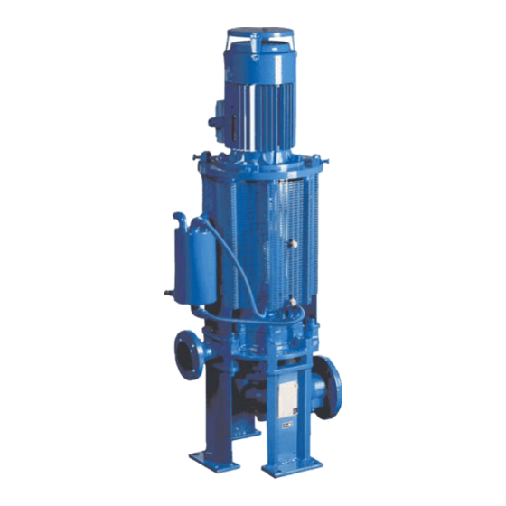
CombiPrime V 2 General Pump description The CombiPrime V is a range of vertical self-priming centrifugal pumps. Hydraulic application area complies with EN 733 (DIN 24255) (with the exception of 250B-315). The flange dimensions, bolt circle and number of holes comply with ISO 7005 ND 10. The CombiPrime V is characterized by the built-in vacuum pump. -
Page 15: Serial Number
Serial number Serial number of the pump or pump unit are shown on the name plate off the pump and on the label on the cover of this manual. Example: 01-1000675A year of manufacture 100067 unique number number of pumps pump with motor pump with free shaft end Applications... -
Page 16: Shaft Sealing
CombiPrime V 2.5.2 Shaft sealing On both sides of the self-priming part there is a mechanical seal or a number of lip seals. Both are mounted on shaft sleeves, which have been sealed in such a way that the pumped liquid cannot touch the pump shaft. The mechanical seals meet EN 12756 (DIN 24960), with the exception of the mounting length. -
Page 17: Re-Use
Re-use The pump may only be used for other applications after prior consultation with Johnson Pump or your supplier. Since the lastly pumped medium is not always known, the following instructions should be observed: • Flush the pump properly. • Make sure the flushing liquid is discharged safely (environment!) Take adequate precautions and use the appropriate personal protection means (rubber gloves, spectacles)! Scrapping... -
Page 18: Installation
CombiPrime V 3 Installation Safety • Read this manual carefully prior to installation and commissioning. Non-observance of these instructions can result in serious damage to the pump and this will not be covered under the terms of our guarantee. Follow the instructions given step by step. •... -
Page 19: Mounting
Mounting 3.4.1 Installation of a pump unit Pump and motor shafts of complete pump units are adjusted perfectly in line in the works. 1 In case of permanent arrangement place the base plate level on the foundation with the aid of shims. 2 Carefully tighten the nuts on the foundation bolts. -
Page 20: Alignment Of The Coupling
CombiPrime V 3.4.3 Alignment of the coupling 1 Use bolts (0890) to position the electric motor in such a way that the coupling halves are aligned correctly. 2 Place a ruler against the coupling. The ruler should touch both coupling halves over the entire length, see figure 2A. -
Page 21: Piping
Piping • The piping to the suction and delivery connections must fit exactly and must not be subject to stress during operation. • The passage of the suction pipe must be amply dimensioned. This pipe should be as short as possible and run towards the pump in such a way that no air pockets can arise. -
Page 22: Vacuum Pump With Service Liquid Tank
CombiPrime V Vacuum pump with service liquid tank 3.7.1 Mounting of accessories • Connect a pipe to the overflow of the service liquid tank to discharge excess service liquid and extracted air. • The pump is supplied with the exhaust pipe connected to the pump cover. 3.7.2 Connection diagram with service liquid tank Figure 4:... -
Page 23: Installation Examples With Service Liquid Tank
3.7.4 Installation examples with service liquid tank For a few situations is shown how pumps with a service liquid tank can be installed. Excess service liquid must always be discharged to the suction tank separately. Figure 5: Medium: thin, clean and slightly polluted liquids. Installation CV/EN (1009) 5.3... - Page 24 CombiPrime V Figure 6: Medium: thin liquids, polluted with highly abrasive constituents. The back blades on the centrifugal impeller prevent heavy abrasive matter from getting into the suction space behind the impeller. To prevent floating abrasive matter from penetrating the pump, mount a filter in the suction pipe.
- Page 25 Figure 7: Medium: thin, clean and slightly polluted liquids. In case part of the suction pipe lies higher than the pump, venting should also be provided in this part. If the suction pipe is short, or the lift in the suction pipe small, venting at the highest point is not necessary.
- Page 26 CombiPrime V Figure 8: Medium: thin, clean and slightly polluted liquids. In case of long suction pipes (10 m or more) and a high suction head (4-7 m), also the suction pipe must be vented. Installation CV/EN (1009) 5.3...
-
Page 27: Vacuum Pump With Float-Controlled De-Aerator
Vacuum pump with float-controlled de-aerator 3.8.1 Mounting of accessories • Connect the exhaust pipe of the float-controlled de-aerator to the suction pipe. The passage of the exhaust pipe must be approx. 12 mm and the connection to the suction pipe at least G1/2". •... -
Page 28: Installation Examples With Float-Controlled De-Aerator
CombiPrime V 3.8.4 Installation examples with float-controlled de-aerator For a few situations is shown how pumps with a float-controlled de-aerator can be installed. The excess service liquid is always returned to the suction pipe. Figure 10: Medium: thin, clean and slightly polluted liquids. Installation CV/EN (1009) 5.3... - Page 29 Figure 11: Medium: thin liquids polluted with highly abrasive matter. The back blades on the centrifugal impeller prevent heavy abrasive matter from getting into the suction space behind the impeller. To prevent floating abrasive matter from penetrating the pump, mount a filter in the suction pipe. The straining capacity of the filter should correspond with the nature of the pollutant.
- Page 30 CombiPrime V Figure 12: Medium: thin, clean and slightly polluted liquids. In case part of the suction pipe lies higher than the pump, venting should also be provided in this part. If the suction pipe is short, or the lift in the suction pipe small, venting at the highest point is not necessary.
-
Page 31: Connection Of The Electric Motor
Figure 13: Medium: thin, clean and slightly polluted liquids. In case of long suction pipes (10 m or more) and a high suction head (4 -7 m), also the suction pipe must be vented. Connection of the electric motor The electric motor must be connected to the mains by an approved electrician, according to the locally prevailing regulations of the electricity company. -
Page 32: Commissioning
CombiPrime V 4 Commissioning Inspection of the pump Check whether the pump shaft turns freely. Do this by turning the shaft end at the coupling a few times by hand. Inspection of the vacuum pump part 1 Check whether all piping between the pump wheel casing and the service liquid tank (version TL) or the float-controlled de-aerator (version VL) have been connected. -
Page 33: Adjusting The Air-Inlet Valve
Adjusting the air-inlet valve The air-inlet valve (1650) serves to admit small quantities of air into the self- priming system. The vacuum pump has been designed to pump a large quantity of air. After the suction phase, the vacuum pump functions as liquid pump. However, in principle it is not designed to only pump liquid. -
Page 34: Maintenance
CombiPrime V 5 Maintenance Daily maintenance Regularly check the outlet pressure. No water should get into the terminal box of the electric motor when the pump room is sprayed clean! Never spray water on hot pump parts! The sudden cooling down may cause them to burst and hot water may flow out! Service liquid After the pump has been put into operation once, the working-liquid tank and the float- controlled de-aerator don't have to be filled up again: there is constantly a sufficient... -
Page 35: Environmental Influences
Environmental influences • Regularly clean the filter in the suction pipe or the suction strainer at the bottom of the suction pipe, as the inlet pressure may become too low if the filter or the suction strainer is fouled. • If there is a risk that the pumped liquid expands during solidification or freezing, the pump has to be drained and, if necessary, flushed after it has been put out of service. -
Page 36: Problem Solving
CombiPrime V 6 Problem solving Faults in a pump installation can have various causes. The fault may not be in the pump, it may also be caused by the pipe system or the operating conditions. Firstly, always check that installation has been executed in accordance with the instructions in this manual and that the operating conditions still correspond with the specifications for which the pump was purchased. - Page 37 Table 4: Possible causes of pump failures. Possible causes Service liquid tank or float de-aerator not filled with liquid Gas or air coming from the liquid Air lock in the suction pipe Air leak in the suction pipe The manometric suction head is too high Suction pipe or suction strainer is blocked 10 Insufficient immersion of foot valve or suction pipe during operation of the pump 11 NPSH available too low...
-
Page 38: Disassembly And Assembly
CombiPrime V 7 Disassembly and assembly Precautionary measures Take adequate measures to avoid that the motor is started while you are working on the pump. This is especially important for electric motors with remote control: • Switch the operating switch near the pump (if available) to "OFF". •... -
Page 39: Constructive Variants
Constructive variants The pumps can be supplied in various constructive variants. Each variant has a code which is stated in the type identification on the name plate on the pump. Table 5: Constructive variants codes. mechanical seal on shaft sleeve lip seals on shaft sleeve service liquid tank + air inlet valve float de-aerator + air inlet valve... -
Page 40: Replacing The Impeller And The Wear Ring
CombiPrime V Replacing the impeller and the wear ring The play between the impeller and the wear ring is 0,3 mm to the diameter at delivery. In case the play has increased to 0,5-0,7 mm due to wear, the impeller and the wear ring should be replaced. -
Page 41: Disassembling Of The Wear Ring
7.7.3 Disassembling of the wear ring After removing the Top Pull Out unit the wear ring can be removed. In most cases the ring has been fixed so tightly that it cannot be removed undamaged. Figure 15: Removal of wear ring. 1 Measure the thickness (d) and the width (b) of the ring, see figure 15 A. -
Page 42: Shaft Sealing
CombiPrime V Shaft sealing 7.8.1 Disassembly of the mechanical seal M2 Figure 16: Mechanical seal M2 (A = bearing groups 1 and 2, B = bearing group 3). The item numbers used are referring to figure 16. 1 Remove the impeller, see paragraph 7.7.1 "Disassembly of the impeller". 2 Pull the shaft sleeve (1900) from the pump shaft and remove the rotating part of the mechanical seal from the shaft sleeve. -
Page 43: Instructions For Mounting A Mechanical Seal
7.8.2 Instructions for mounting a mechanical seal ➢ First read the following instructions regarding the mounting of a mechanical seal. Follow these instructions closely when mounting a mechanical seal. • A mechanical seal is a fragile precision instrument. Leave the seal in its original packing until you are ready to fit it! •... -
Page 44: Disassembly Of The Lip Seals M4
CombiPrime V 7.8.4 Disassembly of the lip seals M4 Figure 17: Lip seal M4. The item numbers used are referring to figure 17. 1 Remove the impeller, see paragraph 7.7.1 "Disassembly of the impeller". 2 Mark the position of the pump cover (0110) in relation to the bearing bracket (2100). 3 Loosen the Allen screws (1880). -
Page 45: Instructions For Mounting A Lip Seal
7.8.5 Instructions for mounting a lip seal ➢ First read the following instructions regarding the mounting of a lip seal. Follow these instructions closely when mounting a lip seal. • A lip seal is a fragile precision instrument. Leave the seal in its original packing until you are ready to fit it! •... - Page 46 CombiPrime V Bearing 7.9.1 Disassembling bearing Figure 18: Bearing. The item numbers used are referring to figure 18. 1 Disassemble the impeller and the shaft seal, see paragraph 7.7.1 "Disassembly of the impeller" and paragraph 7.8.1 "Disassembly of the mechanical seal M2" / paragraph 7.8.4 "Disassembly of the lip seals M4".
- Page 47 7.9.2 Assembling bearing Make sure your working environment is clean and leave the bearings in their original packing until you are ready to mount them. 1 Clean the interior of the bearing bracket properly. 2 Mount the NILOS-Rings (2310 and 2320) on the pump shaft. Make sure they are in the right place and position.
- Page 48 CombiPrime V 7.10 Adjustment of the axial play After repairs to the pump, the axial play of the pump wheel has to be adjusted. This play has to be equal on both sides. This adjustment can be done in the following way, see figure 19: Figure 19: Adjustment of the axial play.
- Page 49 Disassembly and assembly CV/EN (1009) 5.3...
- Page 50 CombiPrime V 8 Dimensions Dimensions delivery flange Figure 20: Dimensions delivery flange. ISO 7005 PN 16 aj x al 4 x 18 4 x 18 4 x 18 4 x 18 8 x 18 8 x 18 8 x 18 8 x 23 ISO 7005 PN 16 aj x al...
- Page 51 Dimensions suction flange Figure 21: Dimensions suction flange. ISO 7005 PN 16 ai x ak 4 x 18 8 x 18 8 x 18 8 x 18 8 x 22 ISO 7005 PN 10 ai x ak 8 x 22 12 x 22 Dimensions CV/EN (1009) 5.3...
- Page 52 CombiPrime V Dimensions foot pads Figure 22: Dimensions foot pads (Top view)..-160 ...-200 ...-250 ...-315 ...-400 Dimensions foot pads 200-200 / 250B-315 Figure 23: Dimensions foot pads (Top view). 200-200 250B-315 Dimensions CV/EN (1009) 5.3...
- Page 53 Pump dimensions Figure 24: Pump dimensions. Standard: • disassembly opening lantern: pos A • junction box electric motor: pos 1 Dimensions CV/EN (1009) 5.3...
- Page 54 CombiPrime V 90S/L 160M/L 225S/M 100L 132S/M 180M/L 250M 112M 200L 280S/M 32-160 32-200 40-160 40-200 40-250 50-160 50-200 50-250 65-160 65-200 65-250 65-315 80-160 80-200 80-250 80-315 80-400 100-200 100-250 100-315 100-400 125-250 125-315 125-400 150-315 150-400 200-200 250B-315 (200-200 =..-250) F165...
- Page 55 Pump dimensions with suction bend Figure 25: Pump dimensions with suction bend. Standard: • disassembly opening lantern: pos A • suction bend: pos I • junction box electric motor: pos 1 Dimensions CV/EN (1009) 5.3...
- Page 56 CombiPrime V 90S/L 160M/L 225S/M 100L 132S/M 180M/L 250M 112M 200L 280S/M 32-160 32-200 40-160 40-200 40-250 50-160 50-200 50-250 65-160 65-200 65-250 65-315 80-160 80-200 80-250 80-315 80-400 100-200 100-250 100-315 100-400 125-250 125-315 125-400 150-315 150-400 (200-200 =..-250) F165 F215 F265...
- Page 57 Pump dimensions 200-200 / 250B-315 with suction bend Figure 26: Pump dimensions 200-200 / 250B-315 with suction bend. Standard: • disassembly opening lantern: pos A • suction bend: pos I • junction box electric motor: pos 1 Dimensions CV/EN (1009) 5.3...
- Page 58 CombiPrime V 160L 225S/M 180M/L 250M 200L 280S/M 225M02 315S/M2 poles 200-200 18”x9,5 250B-315 20”x9,5 F300 F350 F400 sv max 160M 160L 180M 180L 200L 225S 225M 200-200 250B-315 Dimensions CV/EN (1009) 5.3...
- Page 59 Pump dimensions with service liquid tank Figure 27: Pump dimensions with service liquid tank. Dimensions CV/EN (1009) 5.3...
- Page 60 CombiPrime V 32-160 32-200 40-160 40-200 40-250 50-160 50-200 50-250 65-160 65-200 65-250 65-315 80-160 80-200 80-250 80-315 80-400 100-200 100-250 100-315 100-400 125-250 125-315 125-400 150-315 150-400 200-200 250B-315 * n = 3000-3600 min ** n = 1500-1800 min Connections De-aeration / Overflow Rp 1/2...
- Page 61 Pump dimensions with float de-aerator 4163_A Figure 28: Pump dimensions with float de-aerator. Dimensions CV/EN (1009) 5.3...
- Page 62 CombiPrime V 32-160 32-200 40-160 40-200 40-250 50-160 50-200 50-250 65-160 65-200 65-250 65-315 80-160 80-200 80-250 80-315 80-400 100-200 100-250 100-315 100-400 125-250 125-315 125-400 150-315 150-400 200-200 250B-315 * n = 3000-3600 min ** n = 1500-1800 min Connections De-aeration Rp 1/2...
- Page 63 Dimensions CV/EN (1009) 5.3...
- Page 64 CombiPrime V 9 Parts Ordering parts 9.1.1 Order form You can use the order form included in this manual for ordering parts. When ordering parts always quote the following data: 1 Your address. 2 The quantity, the item number and the description of the part. 3 The pump number.
- Page 65 Pump 9.2.1 Sectional drawing Figure 29: Sectional drawing. Parts CV/EN (1009) 5.3...
- Page 66 CombiPrime V 9.2.2 Parts list Material Item Quantity Description 0100 pump casing cast iron bronze aluminium aluminium 0120* impeller cast iron bronze bronze bronze bronze 0130* wear ring cast iron bronze 0200 coupling half, pump side cast iron 0210 spacer sleeve cast iron 0220 coupling half, motor side...
- Page 67 Material Item Quantity Description 2310* NILOS-Ring steel 2320 NILOS-Ring steel 2340 adjusting ring steel 2350 spacer sleeve steel 2360* outer circlip spring steel 2400 name plate stainless steel 2410 arrow plate aluminium 2810 Allen screw steel 2815 Allen screw steel Quantity dependent on pump type.
- Page 68 CombiPrime V Shaft sealing group M2 9.3.1 Mechanical seal MG1-G60 Figure 30: Mechanical seal MG1-G60 (A = bearing group 1 and 2, B = bearing group 3). 9.3.2 Parts list mechanical seal MG1-G60 Material Item Quantity Description 0110 pump cover cast iron bronze 1220*...
- Page 69 Shaft sealing group M4 9.4.1 Lip seal Figure 31: Lip seal. 9.4.2 Parts list lip seal Material Item Quantity Description 0110 pump cover cast iron bronze 1361* gasket 1500* pump wheel bronze 1510 pump wheel casing cast iron bronze 1710 steel stainless steel pipe nipple...
- Page 70 CombiPrime V Service liquid tank TL 9.5.1 Service liquid tank TL Figure 32: Service liquid tank TL. Parts CV/EN (1009) 5.3...
- Page 71 9.5.2 Parts of service liquid tank TL Material Item Quantity Description 1400 pipe nipple stainless steel 1501 pipe stainless steel 1502 male connector stainless steel 1503 male connector steel stainless steel 1504** washer stainless steel 1511 non-return valve NBR/brass stainless steel 1550 elbow steel...
- Page 72 CombiPrime V Float de-aerator VL 9.6.1 Float de-aerator VL Figure 33: Float de-aerator VL. Parts CV/EN (1009) 5.3...
- Page 73 9.6.2 Parts of float de-aerator VL Material Item Quantity Description 1400 pipe nipple stainless steel 1501 pipe stainless steel 1502 male connector stainless steel 1503 male connector steel stainless steel 1504** washer stainless steel 1511 non-return valve NBR/brass stainless steel 1520 double nipple ductile iron...
- Page 74 CombiPrime V Suction bend 9.7.1 Sectional drawing suction bend Figure 34: Sectional drawing suction bend. 9.7.2 Parts of suction bend Material Item Quantity Description cast iron bronze 0350 plug steel stainless steel 0360 gasket rubber 0400 suction bend cast iron bronze 0410 support...
- Page 75 9.7.3 Sectional drawing suction bend 200-200 / 250B-315 Figure 35: Sectional drawing suction bend 200-200 / 250B-315. 9.7.4 Parts of suction bend 200-200 / 250B-315 Material Item Quantity Description cast iron bronze 0350 plug steel stainless steel 0360 gasket rubber 0400 suction bend steel...
- Page 76 CombiPrime V 10 Technical data 10.1 Recommended greases Table 6: Recommended greases according to classification NLGI-3. Energrease LS-EP 3 CHEVRON MultifaK Premium 3 Beacon EP 3 EXXONMOBIL Mobilux EP 3 SHELL Alvania RL3 LGMT 3 TOTAL Total Lical EP 2 Quantity grease/bearing [gr] = 0,005 * Outer diameter of bearing [mm] * Bearing width [mm] 10.2 Recommended locking liquids...
- Page 77 10.4 Hydraulic performance Figure 36: Performance overview 3000 min Figure 37: Performance overview 1500 min Technical data CV/EN (1009) 5.3...
- Page 78 CombiPrime V Figure 38: Performance overview 3600 min Figure 39: Performance overview 1800 min Technical data CV/EN (1009) 5.3...
- Page 79 10.5 Noise data 10.5.1 Pump noise as a function of pump power [dB(A)] P [kW] Figure 40: Noise level as function of pump power [kW] at 1450 min A = sound energy, B = sound pressure. [dB(A)] P [kW] Figure 41: Noise level as function of pump power [kW] at 2900 min A = sound energy, B = sound pressure.
- Page 80 CombiPrime V 10.5.2 Noise level of entire pump unit L [dB] 9 10 11 12 13 14 15 16 17 18 19 20 |L1 - L2| [dB] Figure 42: Noise level of entire pump unit. In order to determine the total noise level of the entire pump unit, the noise level of the motor must be added to that of the pump.
- Page 81 Technical data CV/EN (1009) 5.3...
- Page 82 CombiPrime V Index Accessories mounting ....20, 21, 26 Grease ......75 Adjusting the air-inlet valve .
- Page 83 Noise ......32, 34 Pallets ......11 Piping .
- Page 84 Order form for spare parts FAX Nr. ADDRESS Your order will only be dealt with if this order form has been correctly completed and signed. Order date: Your order number: Pump type: Execution: Quantity Item. No. Part Article number pump Delivery address: Invoicing address: Ordered by:...
- Page 85 ORDFORM (0804) 3.1 EN...
- Page 86 SPX Corporation reserves the right to incorporate our latest design and material changes without notice or obligation. Design features, materials of construction and dimensional data, as described in this bulletin, are provided for your information only and should not be relied upon unless confirmed in writing.
Need help?
Do you have a question about the Johnson Pump CombiPrime V and is the answer not in the manual?
Questions and answers