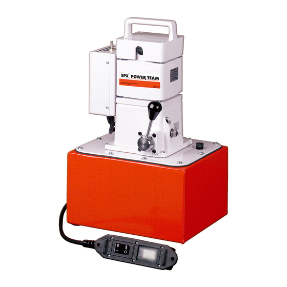
SPX Power Team PE18 Series Operating Instructions Manual

SPX Power Team PE18 Series Operating Instructions Manual

Electric-powered/hydraulic pump

Advertisement

Operating Instructions for:
PE18 Series
Electric-Powered
18 Series
Hydraulic Pump
Form No. 1000572
Rev. 0 February 8, 2012
© SPX

Advertisement

Table of Contents
loading

Summary of Contents for SPX Power Team PE18 Series

  • Page 1 Operating Instructions for: PE18 Series Electric-Powered 18 Series Hydraulic Pump Form No. 1000572 Rev. 0 February 8, 2012 © SPX...
  • Page 2 Form No. 1000572 Rev. 0 February 8, 2012 © SPX...
  • Page 3: Table Of Contents

    Power Team Facilities ..........22 Form No. 1000572 Rev. 0 February 8, 2012 © SPX...
  • Page 4: Description

    The 1/2 hp, 110/115 or 220/230 VAC, 60/50 Hz single phase motor starts under load, even at reduced voltage. The weight can be up to 29 kg (63 lbs). Figure 1. Electric Motor Form No. 1000572 Rev. 0 February 8, 2012 © SPX...
  • Page 5: Control Valves

    Pump “ON” Pump “OFF” Diagrams Port “A” Port “A” PE183A From From Tank Pump Tank Pump NOTE: All ports OPEN to tank during transition between valve positions. Table 1. Pump Configurations Form No. 1000572 Rev. 0 February 8, 2012 © SPX...
  • Page 6 Solenoid “ON” Solenoid “ON” Solenoid “OFF” From From From Tank Pump Tank Pump Tank Pump NOTE: All ports OPEN to tank during transition between valve positions. Table 1. Pump Configurations (continued) Form No. 1000572 Rev. 0 February 8, 2012 © SPX...
  • Page 7: Safety Symbols And Definitions

    • Retract the system before adding fluid to prevent overfilling the pump reservoir. An overfill can cause personal injury due to excess reservoir pressure created when cylinders are retracted. • The load must be under operator control at all times. Form No. 1000572 Rev. 0 February 8, 2012 © SPX...
  • Page 8 Hoses also must not come in contact with corrosive material such as creosote- impregnated objects and some paints. Consult the manufacturer before painting a hose. Never paint the couplers. Hose deterioration due to corrosive materials may result in personal injury. Form No. 1000572 Rev. 0 February 8, 2012 © SPX...
  • Page 9 All personnel must be clear of the load before lowering. • Never use extreme heat to disassemble a hydraulic cylinder or ram. Metal fatigue and/ Form No. 1000572 Rev. 0 February 8, 2012 © SPX...
  • Page 10 SAE grade 8 or better fasteners when attaching components to cylinders or rams and tighten securely. • Limiting the stroke and pressure on all cylinders will prolong their life. Form No. 1000572 Rev. 0 February 8, 2012 © SPX...
  • Page 11: Initial Setup

    • Check the voltage at the motor with the pump running at full pressure. • Never run the motor on long, light gauge extension cords. Refer to Table 2. Minimum Recommended Gauge Table. Form No. 1000572 Rev. 0 February 8, 2012 © SPX...
  • Page 12 IMPORTANT: Some spring return cylinders or rams have a cavity in the rod which forms an air pocket. This type of cylinder or ram should be bled when positioned upside down or lying on its side with the port facing upward. Form No. 1000572 Rev. 0 February 8, 2012 © SPX...
  • Page 13 T-adapter. Install the T-adapter as shown. 3. Install sealant tape or non hardening sealer to the gauge. 4. Install the pressure gauge. Item Description Gauge Hose T-adapter Figure 3. 18-Series Gauge Form No. 1000572 Rev. 0 February 8, 2012 © SPX...
  • Page 14: Operating Instructions

    The switch will automatically return to OFF position when switch is released and pump motor will turn off. Figure 6. Momentary ON-OFF Push Button Remote Motor Control Form No. 1000572 Rev. 0 February 8, 2012 © SPX...
  • Page 15 The pressure switch must be set at a higher pressure than working range to prevent shut down during adjustment. It is also possible to bypass the pressure switch contacts by holding the start switch or remote control switch so the motor runs continuously. Form No. 1000572 Rev. 0 February 8, 2012 © SPX...
  • Page 16 The pressure regulating valve bypasses this surplus fluid, preventing it from going into the system. As a result, the pressure differential can be held to approximately 20 bar (300 psi). Form No. 1000572 Rev. 0 February 8, 2012 © SPX...
  • Page 17: Performance Specifications

    690 bar (100 psi) (700 psi) (1,000 psi) (5,000 psi) (10,000 psi) PE18 690 bar (10,000 psi) * Typical delivery. Actual flow varies with field conditions. Table 4. Fluid Pressure Chart Form No. 1000572 Rev. 0 February 8, 2012 © SPX...
  • Page 18: General Maintenance

    The frequency of fluid changes depends upon general working conditions, severity of use, the overall cleanliness and care given to the pump. Fluid should be changed more frequently Form No. 1000572 Rev. 0 February 8, 2012 © SPX...
  • Page 19 5. Use only Power Team hydraulic fluid AW 46 47 cSt @ 38°C (247 SUS @ 100°F). If low temperature requirements are needed, use hydraulic fluid 5.1 cSt @ 100°C (451 cSt @ -40°C). Form No. 1000572 Rev. 0 February 8, 2012 © SPX...
  • Page 20 2. The brush assemblies must be replaced if they are 4.7mm (3/16") long or less. See Figure 9. 3. Install brush assemblies and brush holder caps. Replace when 4.7 mm (3/16") or less 22 mm (7/8") (new) Figure 9. Brush Inspection Form No. 1000572 Rev. 0 February 8, 2012 © SPX...
  • Page 21: Troubleshooting Guide

    Reset thermal protector. disengaged (three-phase motor). (Single-phase motor will reset Thermal protector open. automatically.) 7. Faulty thermal protector (single- 7. Replace defective parts. phase motor). Faulty magnetic starter (three-phase motor). Form No. 1000572 Rev. 0 February 8, 2012 © SPX...
  • Page 22 9. Power unit/reservoir capacity 9. Use smaller cylinder(s) or larger is too small for the size of the reservoir. cylinder(s) used. 10. Vacuum in reservoir. 10. Clean plugged vent in filler plug. Form No. 1000572 Rev. 0 February 8, 2012 © SPX...
  • Page 23 3. Attached component sticking or 3. Refer to manufacture's binding. information for attached component. 4. Malfunctioning valve. 4. Verify connections. Contact authorized Power Team Service Center. Form No. 1000572 Rev. 0 February 8, 2012 © SPX...
  • Page 24: Power Team Facilities

    Power Team Facilities UNITED ST ATES CHINA EUROPE C E R T I F I E D SPX Hydraulic Technologies Albert Thijsstraat 12 No. 1568 Hua Shan Road International Park Center 6471 WX Eygelshoven 5885 11th Street Shanghai 200052, China...

Table of Contents