
Related Manuals for SPX TopLobe Series


Summary of Contents for SPX TopLobe Series
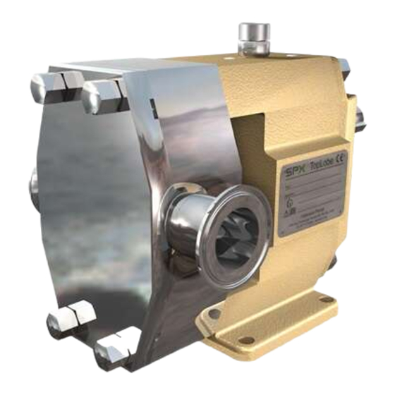
- Page 1 Instruction Manual TopLobe Rotary Lobe Pumps Read and understand this manual prior to operating or servicing this product. A.0500.251 – IM-TL/13.00 EN (08/2009)
- Page 2 EC-Declaration of conformity (as per EC's Machinery Directive 98/37/EC, Annex IIA) Producer SPX Process Equipment AB P.O. Box 1436 SE-701 14 Örebro, Sweden We hereby guarantee that: TopLobe lobe rotor pumps : type: TL1/0039 TL3/0234 TL1/0100 TL3/0677 TL1/0139 TL3/0953 TL2/0074...
-
Page 3: Table Of Contents
Contents 1.0 Introduction ..................7 General ......................7 Receipt, storage and handling ..............7 1.2.1 Receipt, storage......................7 1.2.2 Handling ........................7 General safety instructions ................ 8 1.3.1 General ........................8 1.3.2 Pump units ......................10 1.3.2.1 Pump unit handling ................10 1.3.2.2 Installation ..................... - Page 4 4.0 Disassembly and assembly instructions ........33 Tools to be used ..................35 General instructions ................. 36 O-rings and lip seals ................. 36 Shutdown ....................36 Tightening torque [Nm] for nuts and screws ......... 37 Disassembly ....................38 4.6.1 Pump cover and rotor removal ................38 4.6.2 Disassembly of seals ....................
- Page 5 Gearbox ..................... 65 6.4.1 Gearbox complete ....................65 6.4.1.1 Part list - Gearbox ....................66 6.4.2 Feet options ......................67 6.4.3 Service kit for gearbox ..................68 7.0 Single mechanical seal ..............69 General information ................. 69 Machined parts - Seal assembly parts and flush covers ......70 Seal options ....................
- Page 6 12.0 Valves ....................95 12.1 Heating and cooling jackets..............95 12.2 Built-on safety relief valves ..............95 12.2.1 General description ....................96 12.2.2 Safety relief valve – Spring loaded ..............97 12.2.2.1 Spring loaded ..................97 12.2.2.2 Spring loaded completely opened ............97 12.2.3 Safety relief valve –...
-
Page 7: Introduction
1.0 Introduction General The range of TopLobe rotary lobe pumps are manufactured by SPX Process Equipment, Sweden, and are sold and marketed by a network of authorized distributors. This instruction manual contains necessary information of the TopLobe pumps and must be read carefully before installation, service and maintenance. -
Page 8: General Safety Instructions
Do not exceed the pump’s maximum operating pressure, speed or temperature. Do not modify the operating parameters/system for which the pump was orginally delivered without first consulting SPX Process Equipment. • Pump installation and operation must always comply with prevailing health and safety regulations. - Page 9 • Caution must be taken when lifting the pump, appropriate lifting devices should be used if possible. Lifting rings fitted to the pump are only to be used for lifting the pump, not for lifting the pump with drive and/or baseplate. For baseplate mounted pumps the baseplate is to be used for all lifting purposes.
-
Page 10: Pump Units
1.3.2 Pump units 1.3.2.1 Pump unit handling Use an overhead crane, forklift or other suitable lifting device. Warning Secure lifting slings around the front If there are lifting rings on both the part of the pump and the back part of pump and the motor the slings may be Never lift the pump unit with only the motor. -
Page 11: Before Commissioning The Pump Unit
The pump unit must not be used with other liquids than those for which it was recommended and sold. If there are any uncertainties contact your SPX Process Equipment sales representative. Liquids, for which the pump is not appropriate, can damage the pump and other parts of the unit as well as cause personal injury. -
Page 12: Pump Designation
Pump designation Example: 0234- 10 11 12 Pump family name TL = TopLobe Gearbox size 1, 2, 3, 4 3/4. Hydraulics indicated with displacement volume per revolution and connection diameter Displacement Connection diameter volume per revolution (in dm Standard pump Enlarged inlet TL1/0039 0.039... - Page 13 PTFE lined O-rings approved Chemraz ® * Kalrez ® 12. Special execution For details please contact SPX Process Equipment. Position deviating from standard marked with X * Kalrez is a registered trademark of DuPont Performance Elastomers. A.0500.251 – IM-TL/13.00 EN (08/2009)
-
Page 14: Pump Model And Serial Number
Pump model and serial number If you require further information regarding the TopLobe pumps, please contact your local distributor quoting the pump model and serial number. This information is stated on the nameplate which is attached to the pump gearbox. If the nameplate is damaged or missing, the serial number is also stamped on the gearbox and rotorcase. -
Page 15: General Performance
General performance The maximum capacity and pressure of the pumps is shown in the curve below, this will give an overview of the application field. The curves show the extreme limits, but for many applications the limits are tighter and therefore when changing the operating conditions of the pump please contact your local distributor to ensure a safe and reliable working pump. -
Page 16: Function, Design, Installation
2.0 Function, design, installation Operating principle Liquid is drawn into the pump as the rotors disengage, forming cavities. The liquid is transported in the cavity of the rotors around the periferi of the rotor case. Liquid is pressured out from the pump as the rotors engage, closing the cavities. Operating parameters The maximum pressure and speed operating data are given in the table below. -
Page 17: System Design And Installation
System design and installation When a pump is to be incorporated in a system, it is considered good practice to, as far as possible, minimise the length of the pipes and the number of pipe fittings (tees, unions, bends etc.) and the restrictions. When designing the suction lines, particular care should be taken. - Page 18 The NPSH available from the system must always exceed the NPSH required by the pump. If the following guidelines are observed it should ensure the best possible suction conditions. • The suction line should have at least the same diametre as the pump connections. •...
-
Page 19: Installations With Cip-Systems, Cleaning In Place
For pumps fitted with quenched/flushed product seals check that all required services for flushing purposes are in place and connected. They must give sufficient flow and pressure for the flushing purposes. Contact SPX Process Equipment for advice. For seal plans, see ’’E, F, G, H manuals’’ respectivley. -
Page 20: Shutdown
• Check that the valves are completely open on both inlet and outlet and that the pipelines are free from obstructions. The TopLobe pumps are of the positive displacement type and should therefore never be operated against a closed valve, as this would result in pressure overload, damages on the pump and possibly damage on the pump system. -
Page 21: Trouble Shooting Chart
Trouble shooting chart A.0500.251 – IM-TL/13.00 EN (08/2009) -
Page 22: Heating And Cooling Jackets
The pressure rating at the ports of the pump cover for heating/cooling is 10 bar and should not be exceeded without contacting SPX Process Equipment for advice. For start-up and shut-down procedures where heating/cooling devices are employed, the heating/cooling medium should circulate 20-45 minutes before start-up and/or shut-down. -
Page 23: Technical Data
3.0 Technical data Rotor clearances Axial clearance lobe / front cover Axial clearance lobe / back side rotorcase Radial clearance lobe / rotorcase top and bottom Clearance lobe / lobe Radial clearance lobe / rotorcase at inlet and outlet 3.1.1 Rotors in duplex steel Dimensions in mm Pump type... -
Page 24: Lubricants
The lower hole is to be plugged with the standard plug, position nr. 0915. The oil level glass is always installed as described above on delivery from SPX Process Equipment. If the customer, after delivery, decides to turn the pump “upside down” in order to have the drive shaft in a different position, then the above instructions must be followed. -
Page 25: Material Specification
Material specification 3.3.1 Machined parts – Pump SPX Process Equipment Europe Pump type Pos. Description material description W.-No. TL1 TL2 TL3 TL4 0010 Rotor case GX2CrNiMoN19-11-2 EN 10213-4 1.4409 A351 CF3M 0020 Rotor X3CrNiMoN27-5-2 EN 10088-3 1.4460 AISI 329(L) 0030... -
Page 26: Dimensional Drawings And Weights
Dimensional drawings and weights 3.4.1 Standard – Horizontal Flanges, see 3.4.4 A.0500.251 – IM-TL/13.00 EN (08/2009) -
Page 27: Vertical Mounting - Thread Connection
3.4.2 Vertical mounting – thread connection Flanges, see 3.4.4. A.0500.251 – IM-TL/13.00 EN (08/2009) -
Page 28: Vertical Mounting - Flange Conncection
3.4.3 Vertical mounting – flange conncection Flanges, see 3.4.4. A.0500.251 – IM-TL/13.00 EN (08/2009) -
Page 29: Flanges
3.4.4 Flanges All thread connections (DIN, SMS, DS, BS, ISO, GAS Thread, NPT Thread) and all clamp connections (ISO, SMS, DIN) All flanges DIN (PN16, PN25) and ANSI (class 150/class 300) 3.4.4.1 Standard pump Dimensions in mm Pump type TL1/0039 TL1/0100 TL1/0139 TL2/0074... -
Page 30: Thread And Clamp Connections
3.4.5 Thread and clamp connections Dimension table, see next page. Thread connections DIN 11851/ ISO 2853 BS 4825 DIN 405 SMS 1145 GAS THREAD DS 722 NPT THREAD Clamp connections ISO 2852 DIN 32676 SMS 3017 A.0500.251 – IM-TL/13.00 EN (08/2009) - Page 31 Dimensions – Thread and clamp connections A.0500.251 – IM-TL/13.00 EN (08/2009)
-
Page 32: Din And Ansi Flanges
3.4.6 DIN and ANSI flanges A.0500.251 – IM-TL/13.00 EN (08/2009) -
Page 33: Weights
Weights 3.5.1 Weights standard pump Standard Vertical pump mounting Pump type weight weight TL1/0039 TL1/0100 TL1/0139 TL2/0074 27.5 TL2/0234 27.5 TL2/0301 28.5 TL3/0234 71.5 TL3/0677 72.5 TL3/0953 74.5 TL4/0535 TL4/2316 TL4/3497 All weights in daN, mass is kg A.0500.251 – IM-TL/13.00 EN (08/2009) -
Page 34: Sound Level
Sound level TL1 – Max. rpm TL2 – Max. rpm dB(A) dB(A) Max. Max. Differential pressure - bar Differential pressure - bar dB(A) TL3 – Max. rpm TL4 – Max. rpm dB(A) Max. Max. Differential pressure - bar Differential pressure - bar A.0500.251 –... -
Page 35: Disassembly And Assembly Instructions
4.0 Disassembly and assembly instruction Tools to be used Type Size or range TL 1 TL 2 TL 3 TL 4 Combination spanner 8 mm Combination spanner 10 mm Combination spanner 17 mm Combination spanner 19 mm Combination spanner 20 mm Combination spanner 24 mm Combination spanner... -
Page 36: General Instructions
Make sure that the personnel is properly instructed and educated. Insufficient or wrong assembly and disassembly can lead to the pump malfunction. SPX Process Equipment is not liable for accidents and damage caused by non-compliance with the guidelines. -
Page 37: Tightening Torque [Nm] For Nuts And Screws
Tightening torque [Nm] for nuts and screws Pos. Description Dimension Torque Dimension Torque 0250 Retainer M10 (X-3CrNiMoN27.5.2) M10 (X-3CrNiMoN27.5.2) 0450 Cap nut M10-M-DIN917 (A4) M12-M-DIN917 (A4) 0455 Cap nut M10-M-DIN917 (A4) M12-M-DIN917 (A4) 0510 Screw M 5X 12-M-(8.8) M 5X 12-M-(8.8) 0512 Screw M 6X 20-DIN7991-(A4) -
Page 38: Disassembly
Disassembly See also section 4.2 General instructions, section 4.3 O-rings and lip seals, 4.4 Shut down and 4.5 Tightening torque for nuts and screws. 4.6.1 Pump cover and rotor removal Do not forget that liquid may still flow out of the rotor case when removing the pump cover. -
Page 39: Single Mechanical Seal
SINGLE MECH. SEAL 4.6.2.1 Single mechanical seal 1. Unscrew the cap nuts (0540) from the stud bolts (0550). 0130 0080 0182 2. Remove the seal cover (0090) by pushing from the 0090 0095 0081 rear end on the stud bolts (0550). 3. -
Page 40: Double Mechanical Seal
Double mechanical seal 4.6.2.4 Double mechanical seal 0130 0090 0095 0182 0101 1. Unscrew the cap nuts (0540) from the stud bolts (0553). 2. Remove the seal cover (0090) by pushing from the rear end on the stud bolts. 3. Remove the first stationary part (0080) and O-rings 0553 (0082) of both mechanical seals from seal cover. -
Page 41: Gearbox Disassembly
4.6.4 Gearbox disassembly Only if section 4.6.1 – 4.6.3 have been completed. 0515 0880 0120 0850 0181 0701 0855 0611 0875 0870 1. Remove key (0611). 2. Remove oil drain plug (0870) with sealing ring (0875) and open the air breather (0850) with sealing ring (0855), drain oil into an appropriate container. - Page 42 Common for TL1, TL2, TL 3 and TL4 7. Remove the gear (0190) together with the locking elements (0651) from the shaft. (For TL3, TL4 locking assembly (0652). If necessary, hit gear with plastic hammer to loosen the locking elements. 8.
-
Page 43: Foot Disassembly
4.6.5 Foot disassembly Remove screws (0525 and/or 0530) and the foot (0070). Pay attention to O-ring (0185). Horizontal Vertical 0185 0185 0070 0070 0525/0530 0525/0530 Assembly See also section 4.2 General instructions, section 4.3. O-rings and lip seals and 4.5 Tightening torque for nuts and screws. 4.7.1 Foot assembly Horizontal... -
Page 44: Gearbox Assembly
4.7.2 Gearbox assembly 0885 For TL1, TL2 and TL3 with ball bearing 0051 0050 0700 0121 0510 0170 0630 0620 1. Position the lip seals (0885) inside the gearbox. 2. Heat the bearings (0700) up to 100°C. Fit the bearing to the lay shaft (0051) ensuring it is pushed properly against the shaft shoulder. - Page 45 Common for TL1, TL2, TL3 and TL4 7. Place bearing covers (0121) and secure them with the screws (0510). 8. Secure the screws with Loctite 243. TL1 and TL2 9. Place the gear (0190), with locking elements (0651) and pressure flange (0172) on the lay shaft. 10.
- Page 46 13. Position the shafts by turning the drive shaft manually as shown in fig "Rotor position". Put the shaft sleeves and rotors on the shaft. 14. Now tighten the screws of the locking assembly in the same way as described for the lay shaft.
-
Page 47: Flushing Cover Assembly
19. Press the external ring of the bearing (0701) by using a tool into the gearbox cover (0120). Surface of the bearing should be aligned with the surface of the gearbox cover. 20. Put the gearbox cover by using tool into position by smoothly tapping with a plastic hammer on the cover. -
Page 48: Rotor Case Assembly
Pump type [mm] TL1/0039 15.9 – TL3/0234 TL1/0100 – TL3/0677 TL1/0139 – TL3/0953 TL2/0074 29.4 TL4/0535 63.9 TL2/0234 17.4 TL4/2316 14.9 TL2/0301 17.4 TL4/3497 14.9 *) Seal marking: Burgmann **) Seal markning: SPX Process Equipment A.0500.251 – IM-TL/13.00 EN (08/2009) -
Page 49: Single Mechanical Seal
SINGLE MECH. SEAL 4.7.5.2 Single mechanical seal 0130 0802 0080 0182 1. See point 1 in section 4.7.5.1 0090 0095 0081 0890 2. Put the shaft sleeve (0130) with the O-ring (0804) on the shaft. Check the position of the lip seal (0890) in case of a flushing cover. -
Page 50: O-Ring Seal
O-RING SEAL 4.7.5.4 O-ring seal 0130 0082 0182 1. Place O-ring seals (0183) in support rings (0097). Next 0802 0890 0090 0095 0183 place both support rings with O-rings (0082) into the seal cover (0090). For pumps without positioning plate (0095) go to point 3. 0804 0936 Pumps with positioning plate (0095) -
Page 51: Rotor And Pump Cover Assembly
Double seal TL2/0234, TL2/0301, High pressure TL2/0074, TL3/0234 TL4/0535, TL4/2316, TL4/3497 High ,low and medium pressure TL3/0677, TL3/0953 Low and medium pressure TL2/TL3 TL2/TL3 0130 0802 0080 0182 0101 0088 0086 0804 0090 0082 0182 0101 0088 0086 0090 0082 0083 0085 0087... - Page 52 Measure the distance between the lobe surface and the mounting surface of the pump cover (0030). Next remove the lobe and peel off the necessary number of layers from the shim (0171) to adjust the distance to the setting dimension given in the table in section 3.1.
-
Page 53: Special Tools
These tools can be ordered from SPX Process Equipment or produced in the own workshop. The article numbers for ordering are indicated in the tables under each drawing/picture together with the dimensions of the tool (if applicable). -
Page 54: Assembly Tool For Lip Seal
Assembly tool for lip seal Place: Gearbox cover Purpose: For fitting the lip seal into the gearbox cover (see section 4.7.2) 0.5 x45° C x45° 2 x45° Pump type Art. No. 3.95608.11 1 ±0.1 19.6 ±0.1 34.5 ±0.1 3.95609.11 – 24.6 ±0.2 –... -
Page 55: Assembly Tool For Cover
Assembly tool for cover Place: Gearbox Purpose: For fitting the gearbox cover on the gearbox (see section 4.7.2) Pump type Art. No. 3.95632.11 19.1 ±0.03 20 +0.1 0.45 x45° +0.2 3.95633.11 24.1 ±0.03 25 +0.1 0.45 x45° +0.2 3.95634.11 38.1 ±0.03 40 +0.1 0.95 x45°... -
Page 56: Sectional Drawings And Part List
6.0 Sectional drawings and part lists Overview 0130 0550 0804 0090 0802 0020 0171 0800 0801 0552 0250 0540 0030 0010 0450 0551 0100 0455 0515 0701 0120 0880 (ext.) 0910 0181 0850 0560 0920 0456 0865 0855 0860 0565 0885 0060 0900... -
Page 57: Recommended Spare Parts
Recommended spare parts For preventive Nos./ service for the next Complete Pos. pump Description coming 3 years overhaul 0010 Rotor case 0020 Rotor 0030 Pump cover Pump cover for heating 0032 Pump cover valve Pump cover valve for heating 0050 Drive Shaft 0051 Lay Shaft... -
Page 58: Recommended Spare Parts
6.2.1 Recommended spare parts For preventive Nos./ service for the next Complete Pos. pump Description coming 3 years overhaul 0560 0561 0562 0565 0611 0620 Locking nut 0630 Locking washer (TL1, TL2, TL3 only) 0651 Locking elements 0652 Locking assembly 0660 Circlip (TL1, TL2, TL3 only) 0700... -
Page 59: Hydraulic Part
Hydraulic part 6.3.1 Hydraulic part complete 0130 0550 0804 0090 0020 0802 0171 0800 0801 0552 0250 0540 0030 0010 0450 0551 0100 Retainer tool TL1, TL2 Nos. / Pos. pump Description TL1/0039 TL1/0100 TL1/0139 TL2/0074 TL2/0234 TL2/0301 0010 Rotor case see 6.3.3 Rotor case options 0020 Rotor... -
Page 60: Topkits Options
6.3.2 TopKits Options 6.3.2.1 Kit for flush covers 0890 0180 0925 0101 0934 0540 0881 0512 0890 0180 0935 0933 0561 0553 0512 0540 0561 0553 Pressure of the flushing: 0.5 bar max. Nos. / TL1/0100 TL2/0234 TL3/0677 TL4/2316 Pos. pump Description TL1/0039... -
Page 61: Service Kit For Quench/Flush
6.3.2.2 Service kit for quench/flush 0890 0180 0881 0881 0890 0180 Nos. / Pos. pump Description Service kit for quench/flush 3.01948.21 3.01949.21 3.01950.21 3.01951.21 0180 O-ring 0.2173.865 0.2173.940 0.2173.947 0.2173.866 0881 V-seal – – – 0.2230.468 0890 Lip seal NBR/SS 0.2234.339 0.2234.497 0.2234.527... -
Page 62: O-Ring Kit For Hydraulic Part
6.3.2.3 O-ring kit for hydraulic part 0804 0802 0801 0800 Nos/ Pos. pump Description O-ring kit FPM 3.01819.11 3.01822.11 3.01825.11 3.01828.11 0800 O-ring 0.2173.934 3.91864.11 0.2173.939 0.2173.950 0801 O-ring 0.2173.935 0.2173.937 0.2173.902 0.2173.965 0802 O-ring 0.2173.903 0.2173.948 0.2173.858 0.2173.966 0804 O-ring 0.2173.936 0.2173.938... -
Page 63: O-Ring Kit For Hydraulic Part With Safety Relief Valve
6.3.2.4 O-ring kit for hydraulic part with safety relief valve 0804 0802 0800 0801 0807 Nos. / TL1/0100 TL2/0234 TL3/0677 TL4/2316 Pos. pump Description TL1/0039 TL1/0139 TL2/0074 TL2/0301 TL3/0234 TL3/0953 TL4/0535 TL4/3497 O-ring kit FPM 3.01819.21 3.01819.31 3.01822.21 3.01822.31 3.01825.21 3.01825.31 3.01828.21 3.01828.31... -
Page 64: Rotor Case Options
6.3.3 Rotor case options 0010 TL1, TL2 Nos. / Pos. pump Description TL1/0039 TL1/0100 TL1/0139 TL2/0074 TL2/0234 TL2/0301 0010 Rotor case 3.14030.11 3.14031.11 3.14032.11 3.14033.11 3.14034.11 3.14035.11 Rotor case enlarged inlet 3.14030.21 3.14031.21 3.14032.21 3.14033.21 3.14034.21 – TL3, TL4 Nos. / Pos. -
Page 65: Gearbox
Gearbox 6.4.1 Gearbox, complete 0455 0515 0701 0120 0910 extern 0850 0880 0181 0560 0865 0920 0456 0855 0860 0565 0885 0060 0900 0915 0905 0870 0070 0185 0701 0660 0875 intern 0525 0525/0530 0520 0172 0651 0651 0190 0620 0170 0630 0121 0510... -
Page 66: Part List - Gearbox
6.4.1.1 Parts list – Gearbox Nos. / Pos. pump Description 0050 Drive shaft 3.94380.11 3.94398.11 3.94415.11 3.94445.11 0051 Lay shaft 3.94381.11 3.94399.11 3.94416.11 3.94446.11 0060 Gearbox 3.14036.11 3.14038.11 3.14043.11 3.14046.11 0070 Foot – horizontal 3.14051.11 3.14052.11 3.14053.11 3.14057.11 Foot – vertical 3.14054.12 3.14055.11 3.14056.11... -
Page 67: Feet Options
6.4.2 Feet options Foot – Horizontal 0070 Foot – Vertical for clamps and thread Foot – Vertical for flanges connections 0700 0700 Nos. / Pos. pump Description 0070 Foot – horizontal 3.14051.11 3.14052.11 3.14053.11 3.14057.11 0070 Foot – vertical thread connection 3.14054.12 3.14055.11 3.14056.11... -
Page 68: Service Kit For Gearbox
6.4.3 Service kit for gearbox 0611 0880 0181 0865 0855 0885 0171 0185 0875 Nos. / Pos. pump Description Serivce kit for gearbox 3.01818.11 3.01821.11 3.01824.11 3.01826.11 0171 Shim 3.94520.11 3.94480.11 3.94521.11 3.94588.11 0181 O-ring 0.2172.902 0.2172.906 0.2172.623 0.2172.632 0185 O-ring 0.2172.929 0.2172.541... -
Page 69: Single Mechanical Seal
7.0 Single mechanical seal General information Without flushing With flushing Design • Balanced mechanical seal. • The stationary seal face is built into the seal cover, which is assembled in the rotor case from the front end, and is locked against rotation by the friction forces of two O-rings. -
Page 70: Machined Parts - Seal Assembly Parts And Flush Covers
Machined parts – Seal assembly parts and flush covers SPX Process Equipment Europe Pump type Pos. Description material description W.-nr. 0090 Seal cover X-2 CrNiMo 17.13.2 EN 10088-3 1.4404 AISI 316L 0095 Positioning plate X-2 CrNiMoN 27.5 EN 10088-3 1.4460 AISI 329(L) –... -
Page 71: Seal Options
Seal options 7.3.1 Single mechanical seal 0130 0550 0182 0930 0931 0090 0095 0540 0936 0100 Single mechanical seal, complete Common parts single mechanical seal Single mechanical seal, complete Nos. / Pos. pump Description 0100 Single mech seal Sic/Sic/FPM 3.94497.11 3.94500.11 3.94503.11 3.94556.11... -
Page 72: Single Mechanical Seal With Quench/Flush
7.3.2 Single mechanical seal with quench/flush 0100 0130 0095 0180 0890 0936 0090 0182 0101 0881 Single mechanical seal, complete Common parts single mechanical seal 0540 0561 0935 0512 Single mechanical seal, complete 0934 0933 0553 Nos. / Pos. pump Description 0100 Single mech seal Sic/Sic/FPm... -
Page 73: O-Ring Kit For Single Mechanical Seal With/Without Quench/Flush
O-ring kit for single mechanical seal with/without quench/ flush 0083 0082b 0082a 0082a 0082b 0083 0082 Nos. / Pos. pump Description O-ring kit FPM 3.01803.11 3.01804.11 3.01805.11 3.01806.11 0082 O-ring 0.2173.901 0.2173.929 0.2173.942 0.2173.967 0083 O-ring 0.2173.941 0.2173.925 0.2173.927 0.2173.968 O-ring kit EPDM 3.01803.12 3.01804.12... -
Page 74: Double Mechanical Seal
8.0 Double mechanical seal General Design • Balanced mechanical seal. • The product side stationary seal face is built into the seal cover which is assembled in the rotor case from the front end and the atmopheric side stationary seal face is built into the flush cover. -
Page 75: Machined Parts - Seal Assembly Parts And Flush Covers
Machined parts – Seal assembly parts and flush covers SPX Process Equipment Europe Pump type Pos. Description material description W.-nr. 0090 Seal cover X-2 CrNiMo 17.13.2 EN 100808-3 1.4404 AISI 316L 0095 Positioning plate X-2 CrNiMoN 27.5 EN 10088-3 1.4460 AISI 329(L) –... -
Page 76: Seal Options
Double seal M74-D60 H gh pressure TL2/TL3 Seal options 8.3.1 Double mechanical seal M74-D60 – TL2/0074 and TL3/0234 0090 0182 0561 0101 0936 Double mechanical seal M74-D60, complete 0130 0180 0512 0553 0095 0100 Nos. / Pos. pump Description TL2/0074 TL3/0234 0100 Double mech seal C/Sic/C/FPM... -
Page 77: Double Mechanical Seal M74-D60 - Tl4/0535, Tl4/2316 And Tl4/3497
Double seal M74-D60 H gh pressure TL2/TL3 8.3.2 Double mechanical seal M74-D60 – TL4/0535, TL4/2316 and TL4/3497 0090 0182 0561 0101 0936 Double mechanical seal M74-D60, complete 0180 0130 0095 0512 0553 0100 Nos. / Pos. pump Description 0100 Double mech seal C/Sic/C/FPM 3.94564.14 0100 Double mech seal Sic/Sic/C/FPM... -
Page 78: Tl3/0953
Double seal M74-D61 8.3.3 Double mechanical seal M74-D61 – TL2/0234, TL2/0301, TL3/0677, TL3/ Low and medium pressure TL2/TL3 0953 0090 0182 0561 0101 0936 Double mechanical seal M74-D61, complete 0130 0180 0512 0553 0100 Nos./ TL2/0234 TL3/0677 Pos. pump Description TL2/0301 TL3/0953 0100... -
Page 79: O-Ring Kit For Double Mechanical Seal
O-ring kit for double mechanical seal 0082 0083 0085 0086 0086 0082a 0082b 0085 0083 0082b 0082a Nos. / TL2/0234 TL3/0677 Pos. pump Description TL2/0074 TL2/0301 TL3/0234 TL3/0953 O-ring kit FPM 3.01812.11 3.01812.21 3.01813.11 3.01813.21 3.01837.11 0082 O-ring 0.2173.929 0.2173.861 0.2173.942 0.2173.863 0.2173.967... -
Page 80: Single And Double O-Ring Seal
9.0 Single and Double O-ring seal General information Single Double Design • The removable O-ring holder (containing the O-rings) is built into the seal cover, which is assembled in the rotor case from the front end, and locked by the friction forces of O-rings. -
Page 81: Seal Options
Seal options 9.2.1 Single O-ring seal 0130 0550 0931 0182 0930 0090 0095 0540 0936 0183 0097 0082 Single O-ring seal, complete Common parts single O-ring seal Nos. / TL1/0100 TL2/0234 TL3/0677 TL4/2316 Pos. pump Description TL1/0039 TL1/0139 TL2/0074 TL2/0301 TL3/0234 TL3/0953 TL4/0535... -
Page 82: Double O-Ring Seal With Quench/Flush
9.2.2 Double O-ring seal with quench/flush 0130 0095 0890 0936 0180 0082 0183 0097 0090 0182 0881 0101 Double O-ring seal, complete Common parts double O-ring seal 0561 0935 0512 0540 0934 0933 0553 Nos. / TL1/0100 TL2/0234 TL3/0677 TL4/2316 Pos. -
Page 83: O-Ring Kit
O-ring kit 9.3.1 O-ring kit for single O-ring seal 0183 0082 0183 0082 0082 Nos. / Pos. pump Description O-ring kit FPM 3.01932.11 3.01933.11 3.01934.11 3.01935.11 0082 O-ring 0.2173.901 0.2173.929 0.2173.942 0.2173.967 0183 O-ring 3.92159.11 0.2173.925 0.2173.909 0.2173.968 O-ring kit EPDM 3.01932.12 3.01933.12 3.01934.12... -
Page 84: O-Ring Kit For Double O-Ring Seal
9.3.2 O-ring kit for double O-ring seal 0082 0183 0082 0183 0082 Nos. / Pos. pump Description O-ring kit FPM 3.01936.11 3.01937.11 3.01938.11 3.01939.11 0082 O-ring 0.2173.901 0.2173.929 0.2173.942 0.2173.967 0183 O-ring 3.92159.11 0.2173.925 0.2173.909 0.2173.968 O-ring kit EPDM 3.01936.12 3.01937.12 3.01938.12 3.01939.12... -
Page 85: Hard Lip Seal
10.0 Hard lip seal 10.1 General Design • The removable support ring (containing the lip seal) is built into the seal cover, which is assembled in the rotor case from the front end, and locked by the friction force of an O-ring. •... -
Page 86: Seal Options
10.2 Seal options 10.2.1 Hard lip seal – TL1, TL2, TL3 0930 0931 0130 0095 0936 0090 0182 0895 0096 0084 Hard lip seal, complete Common parts hard lip seal 0550 0540 Nos. / TL1/0100 TL2/0234 TL3/0677 Pos. pump Description TL1/0039 TL1/0139 TL2/0074... -
Page 87: Hard Lip Seal - Tl4
10.2.2 Hard lip seal – TL4 0130 0090 0930 0931 0936 0084 0082 0895 0096 Hard lip seal, complete Common parts hard lip seal 0550 0540 Nos. / TL4/2316 Pos. pump Description TL4/0535 TL4/3497 0082 O-ring see 10.3 O-ring kit for hard lip 0084 O-ring seal with/without flushing... -
Page 88: Hard Lip Seal With Quench/Flush - Tl1, Tl2, Tl3
10.2.3 Hard lip seal with quench/flush – TL1, TL2, TL3 0180 0936 0130 0095 0101 0895 0934 0890 0090 0182 0096 0084 Hard lip seal with quench/flush, complete Common parts hard lip seal 0540 0553 0512 0933 0561 0935 Nos. / TL1/0100 TL2/0234 TL3/0677... -
Page 89: Hard Lip Seal With Quench/Flush - Tl4
TL 4 10.2.4 Hard lip seal with quench/flush – TL4 0130 0130 0934 0936 0090 0101 0890 0881 0084 0082 0895 0096 Hard lip seal with quench/flush, complete Common parts hard lip seal with quench/flush 0561 0935 0553 0540 0512 0933 Nos. -
Page 90: O-Ring Kit For Hard Lip Seal With/Without Quench/Flush
10.3 O-ring kit for hard lip seal with/without quench/flush 0895 0895 0084 0084 0082 TL1, TL2, TL3 0084 0895 Pos. Nos./ Description TL3* Pump O-ring kit FPM 3.01928.11 3.01929.11 3.01930.11 0084 O-ring 0.2173.904 3.90223.11 0.2173.990 0895 Lip seal 3.94517.11 3.94518.11 3.94519.11 3.95723.11 O-ring kit EPDM... -
Page 91: Quench And Flush Connections
11.0 Quench and Flush connections Several connection types for circulation of quench or flush on the shaft sealing are possible according to Seal plans 52, 53 and 54. These connections are applied on TopLobe with single mechanical seal, double mechanical seal, O-ring seal and hard lip seal types with quench or flush options. They can be connected in different ways. - Page 92 B) Seal plan 52 – Unpressurised double seal Use an external reservoir to provide unpressurised buffer fluid Reservoir Section A-A Valve C) Seal plan 53 – Pressurised double seal Use a pressurised external reservoir to supply clean fluid to the seal chamber. Reservoir pressure is greater than the sealing chamber process pressure.
-
Page 93: Pump Connections In Vertical Position
11.1.2 Pump connections in vertical position A) Seal plan 54 (circulation) or plan 64 (through flow) Use a pressurised external barrier fluid reservoir or system to clean fluid to the seal chamber. Circulation is to be provided by an external pressure system or pump. Section A-A B) Seal plan 52 –... - Page 94 C) Seal plan 53 – Pressurised double seal Use a pressurised external barrier fluid reservoir to supply clean fluid to the seal cham- ber. Reservoir pressure is greater than the sealing chamber process pressure. External pressure Section A-A Reservoir A.0500.251 – IM-TL/13.00 EN (08/2009)
-
Page 95: Valves
The pressure rating at the ports of the pump cover for heating/cooling is 10 bar and should not be exceeded without contacting SPX Process Equipment for advice. For start-up and shut-down procedures where heating/cooling devices are employed, the heating/cooling medium should circulate 20-45 minutes before start-up and/or shut-down. -
Page 96: General Description
TL4/3497 12.2.1 General description Significant for all SPX Process Equipment safety relief valves is that the valve head is built directly into the pump cover. In this way the valve is of the highest hygienic design and easy to clean or check. The head has been designed to maximize the flow passage section and to minimize pressure losses as well as allow particles to pass through. -
Page 97: Safety Relief Valve - Spring Loaded
12.2.2 Safety relief valve - Spring Loaded 12.2.2.1 Spring Loaded Fig. 1 and 2 are showing the design of the spring loaded safety relief valve. The valve head (A) is subjected to the fluid pressure in the rotor case on one side and by spring force on the other side. -
Page 98: Safety Relief Valve - Spring Loaded - Air Lifted
12.2.3 Safety relief valve - Spring loaded - air lifted 12.2.3.1 Spring loaded - air lifted Fig. 4 and 5 are showing the design of the spring loaded - air lifted safety relief valve. The valve head (A) is subjected to the fluid pressure in the rotor case on one side and by spring force on the other side. -
Page 99: Spring Loaded - Air Lifted With Cip/Sip Valve Function
12.2.3.2 Spring loaded - air lifted with CIP/SIP valve function Fig. 6 shows the valve completely opened. The pressure inside chamber (ii) has forced the piston (C) and the valve head (A) which is connected to it to the left against the force of the spring. - Page 100 • Close the discharge valve slowly until the desired set-pressure is reached • Use the retainer tool to turn the adjusting screw of the valve slowly counter clockwise until the discharge pressure is starting to drop away • Check the proper setting of the valve by slowly opening and closing the discharge valve.
-
Page 101: Safety Relief Valve - Air Loaded - Air Lifted
12.2.5 Safety relief valve – Air loaded - air lifted 12.2.5.1 Air loaded Fig 7 and 8 are showing the design of the air loaded - air lifted safety relief valve. The pressure in the control chamber (i) is keeping the valve head in balance with the medium pressure. -
Page 102: Setting And Operating - Air Loaded - Air Lifted Safety Relief Valves
12.2.6 Setting and operating – Air loaded - air lifted safety relief valves To adjust the set-pressure of valve do as follows: • Make sure that the pressure in the control pressure cylinder and the air lift chamber is completely relieved. •... - Page 103 Note: Since the control pressure is depending on the nature of the pumped medium the values given in the table below must be interpreted as guidelines. TL1, TL2 – Control pressure TL1/0039 TL1/0100 TL1/0139 TL2/0074 TL2/0234 TL2/0301 Opening pressure Control pressure (bar) (bar) –...
-
Page 104: Disassembly/Assembly
SPRING-LOADED 13.0 Disassembly/Assembly 13.1 Spring loaded valves 0032 0807 0175 0750 0562 0543 0200 0563 0921 0563 0523 0251 0240 0922 Retainer tool 0220 13.1.1 Disassembly 1. Remove plastic plug (0922). 2. Release the spring (0750) by turning the spring adjusting screw (0251) counter clockwise using the retainer tool. -
Page 105: Spring Loaded - Air Lifted Valves
SPRING-LOADED / AIR-LIFTED 13.2 Spring loaded - air lifted valves 0562 0200 0809 0210 0032 0807 0811 0230 0175 0808 0750 0260 0543 0810 0563 0522 0921 0563 0251 0240 0922 0220 Retainer tool 0523 13.2.1 Disassembly 1. Remove plastic plug (0922). 2. -
Page 106: Air Loaded - Air Lifted Valves
AIR-LOADED / AIR-LIFTED AIR-LOADED / AIR-LIFTED 13.3 Air loaded - air lifted valves 0562 0562 0809 0809 0032 0032 0260 0260 0807 0807 0810 0810 TL1, TL2, TL3 0200 0200 0175 0175 0808 0808 0810 0810 0811 0811 0210 0210 0523 0523 0032... -
Page 107: Dimensional Drawings And Weights
14.0 Dimensional drawings and weights 14.1 Safety relief valves with heating/cooling jacket Dimension table, see next page Vertical mounting Horizontal mounting Jacket Jacket 4xG1/8" 4xG1/8" Relief valve – Spring loaded with jacket Relief valve – Spring loaded with jacket 4xG1/8" Relief valve –... -
Page 108: Weights Safety Relief Valve
Dimensions – Safety relief valves with heating/cooling jacket Dimensions in mm Pump type TL1/0039 jacket – – – spring loaded – – – spring loaded - air lifted 278.5 – – air loaded - air lifted 278.5 – TL1/0100 jacket –... -
Page 109: Sectional Drawings And Parts Lists
SPRING-LOADED 15.0 Sectional drawings and parts lists 15.1 Pump cover with safety relief valve – spring loaded 0032 0807 0175 0750 0562 0543 0200 0563 0921 0563 0523 0251 0240 0922 0220 Nos. / TL1/0100 TL2/0234 TL3/0677 Pos. pump Description TL1/0039 TL1/0139 TL2/0074... -
Page 110: Pump Cover With Safety Relief Valve - Spring Loaded - Air Lifted
SPRING-LOADED / AIR-LIFTED 15.2 Pump cover with safety relief valve – spring loaded - air lifted 0562 0200 0809 0210 0032 0807 0811 0230 0175 0808 0750 0260 0543 0810 0563 0522 0921 0563 0251 0240 0922 0220 0523 Nos. / TL1/0100 TL2/0234 TL3/0677... -
Page 111: Pump Cover With Safety Relief Valve - Air Loaded - Air Lifted - Tl1
AIR-LOADED / AIR-LIFTED 15.3 Pump cover with safety relief valve – air loaded - air lifted – TL1, TL2, TL3 0562 0809 0032 0260 0807 0810 0200 0175 0808 0810 0811 0210 0523 0230 0522 0240 0220 Nos. / TL1/0100 TL2/0234 TL3/0677 Pos. -
Page 112: Pump Cover With Safety Relief Valve - Air Loaded - Air Lifted - Tl4
15.4 Pump cover with safety relief valve – air loaded - air lifted – TL4 0032 0562 0809 0807 0810 0811 0200 0175 0808 0210 0260 0230 0924 0522 0523 0923 0220 Nos. / TL4/2316 Pos. pump Description TL4/0535 TL4/3497 Safety relief valve, complete 3.01863.13 3.01863.23...
Need help?
Do you have a question about the TopLobe Series and is the answer not in the manual?
Questions and answers