Table of Contents
Advertisement
Quick Links
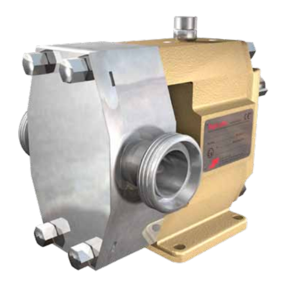
TopLobe
E X P LO S I O N P R OT E CT I O N AC C O R D I N G TO AT E X ( 9 4 / 9 / E C )
A . 0 5 0 1 . 2 5 1 – AT E X I M - T L / 0 5 . 0 0 E N ( 1 2 / 2 0 1 1 )
O R I G I N A L I N S T R U CT I O N S
R E A D A N D U N D E R S TA N D T H I S M A N UA L P R I O R TO O P E R AT I N G O R S E R V I C I N G T H I S P R O D U CT.
I N S T R U CT I O N M A N UA L
Advertisement
Table of Contents

Related Manuals for SPX Johnson Pump TopLobe TL1


Summary of Contents for SPX Johnson Pump TopLobe TL1
- Page 1 I N S T R U CT I O N M A N UA L TopLobe E X P LO S I O N P R OT E CT I O N AC C O R D I N G TO AT E X ( 9 4 / 9 / E C ) O R I G I N A L I N S T R U CT I O N S A .
- Page 2 Declaration of conformity according to EC directive 94/9/EC (ATEX) Manufacturer SPX Flow Technology Sweden AB P.O.Box 1436 SE-701 14 Örebro Sweden Declares hereby that the following product families, if ordered as Atex pump or Atex pump unit, are meeting the requirements set forth in EC directive 94/9/EC of 23 March 1994.
-
Page 3: Table Of Contents
Contents Disclaimer ......................4 General ....................5 Symbol ......................5 Safety Information ..................5 Responsibility for ATEX certification – extend of delivery ....5 Marking ......................6 ATEX type designation examples ............7 Temperature classes and allowable temperatures ......7 1.6.1 II 2G allowable temperature ............7 1.6.2 II 2(G)D allowable temperature ..........8 Responsibility ....................8 Operation .....................8 Monitoring ....................9... -
Page 4: Disclaimer
SPX reserves the right to change the construction and design of the products at any time without being obliged to change previous models accordingly. -
Page 5: General
When in doubt contact your local supplier. In the event SPX delivers a pump with bare shaft, the explosion protection certification marking on the pump nameplate refers exclusively to the pump part. All other assembled equipment should have separate certification of at least the same or higher grade of protection as the pump, delivered by the supplier(s) of that equipment. -
Page 6: Marking
(NNNN indicates the year of production) Ex marking.: example: II 2G c T3-T4 Tech. File Ref.: TFR 03-13347-01/040416 Name plate on the unit (in case of delivery of complete unit by SPX) SPX Flow Technology Sweden AB P.O. Box 1436, SE-701 14 Örebro www.spx.com Type:... -
Page 7: Atex Type Designation Examples
ATEX type designation examples Example 1: Ex II 2G c T3-T4 marking according to Group II, Category 2, Gas (G) protection II 2G marking essential for safe use ignition protection (c = constructional safe) T3-T4 temperature class T3 to T4 Example 2: Ex II 2G c 240°C (T2) II 2G marking according to Group II, Category 2, Gas (G) protection... -
Page 8: 2(G)D Allowable Temperature
1.6.2 II 2(G)D allowable temperature The maximum surface temperature (Tmax) is indicated on the name plate. Tmax is determined as the lowest temperature derived from following equations: • = temperature limits of selected internal materials (i.e. pump selection). • - 75°C (T “ignition temperature of a dust layer of 5 mm thickness”) •... -
Page 9: Monitoring
Monitoring If good function and/or maximum allowable surface temperatures cannot be ensured by regular inspection by the operator, suitable monitoring devices must be provided for. Surface temperature monitoring is always of extreme importance in the following areas, see figure 1: •... -
Page 10: Residual Risks
1.10 Residual risks (based on the risk analysis according to SS-EN13463-1) Potential ignition source Measures applied to prevent the source Ignition protection Normal Foreseeable Rare becoming effective used operation malfunction malfunction The customer has to ensure that the temperature Related to hot of the pump and heating liquid do not exceed the SS-EN 13463-1 §6.1 surfaces of... -
Page 11: Performance
2.0 Performance • Operation of the pump outside its specified operating range may severely jeopardize the whole function of the pump and increase the risk of exceeding allowable temperature limits. See IM. • In order to remove the heat generated by hydraulic and mechanical friction inside the pump, it must be assured that there is always a sufficient minimum flow through the pump. -
Page 12: Installation
3.0 Installation Checks Before installation, the equipment must be checked. • Ensure the equipment data (as indicated on nameplate, documentation etc.) corresponds to the explosive atmosphere zone, category and system requirements. • Possible damage: the installed equipment must be undamaged and must have been properly stored before installation. -
Page 13: Direction Of Rotation
• The compulsory coupling guard must be included in the explosion protection certificate of the drive or pump unit or should be certified separately by the manufacturer or supplier of the guard. The coupling guard must be made of non-sparking materials. Never use light metals containing more than 7.5% magnesium! In case of aluminium coupling parts or belt-pulleys, the coupling guard must be made of brass. -
Page 14: Commissioning
4.0 Commissioning General Take note that rotary lobe pumps are positive displacement pumps and procedures may often differ from procedures commonly used for centrifugal pumps. Follow the instructions in the IM and the separate instructions for the motor drive and coupling. -
Page 15: Maintenance
5.0 Maintenance General • Pumps certified for ‘‘Explosion protection’’ need maintenance and precaution to prevent risks of ignition due to malfunction and unacceptable wear. • Follow the instructions given in the IM. • A decrease of flow rate (or in case the pump does not supply the required pressure) is an indication of a possible malfunction or a sign of internal pump wear and requires maintenance or repairs. -
Page 16: Limiting Risks By Means Of "Check List
6.0 Limiting risks by means of “check list” During installation • Check that the pipes are correctly connected and self supported. The pipe system should not exert excessive forces on the pump connections during operation, including weight of liquid, reaction forces and thermal expansion – have separate pipe supports and compensators been provided for? •... -
Page 17: When The Pump Is Running
When the pump is running • Never close completely the suction valve or regulate the capacity/pressure by means of • Never close outlet valve completely without a safety valve installed – stop the pump by electrically disconnect the motor. • Check the correct operation of the auxiliary circuits, including: quench, flushing, heating. - Page 18 P: +46 (0)19 21 83 00 F: +46 (0)19 27 23 72 E: johnson-pump.se.support@spx.com SPX reserves the right to incorporate our latest design and material changes without notice or obligation. Design features, materials of construction and dimensional data, as described in this bulletin, are provided for your information only and should not be relied upon unless confirmed in writing.
Need help?
Do you have a question about the Johnson Pump TopLobe TL1 and is the answer not in the manual?
Questions and answers