Table of Contents
Advertisement
Quick Links
TopGear H
I N T E R N A L G E A R P U M P S
A . 0 5 0 0 . 3 5 1 – I M - TG H / 0 7 . 0 2 E N ( 1 0 / 2 0 1 5 )
O R I G I N A L I N S T R U CT I O N S
R E A D A N D U N D E R S TA N D T H I S M A N UA L P R I O R TO O P E R AT I N G O R S E R V I C I N G T H I S P R O D U CT.
I N S T R U CT I O N M A N UA L
Advertisement
Table of Contents

Related Manuals for SPX TopGear H Series


Summary of Contents for SPX TopGear H Series
- Page 1 I N S T R U CT I O N M A N UA L TopGear H I N T E R N A L G E A R P U M P S O R I G I N A L I N S T R U CT I O N S A .
-
Page 2: Evenbroekveld
EC-Declaration of conformity Machinery Directive 2006/42/EC, Annex IIA Manufacturer SPX Flow Technology Belgium NV Evenbroekveld 2-6 BE-9420 Erpe-Mere Belgium Herewith we declare that TopGear H-range Gear Pumps Types: TG H2-32 TG H3-32 TG H6-40 TG H15-50 TG H23-65 TG H58-80... -
Page 3: Table Of Contents
Contents Introduction ________________________________________________7 1.1 General ___________________________________________________7 1.2 Reception, handling and storage _______________________________7 1.2.1 Reception _________________________________________________ 7 1.2.2 Handling __________________________________________________ 7 1.2.3 Storage ___________________________________________________ 7 1.3 Safety _____________________________________________________8 1.3.1 General ___________________________________________________ 8 1.3.2 Pump units ________________________________________________ 9 1.3.2.1 Pump unit handling ________________________________________9 1.3.2.2 Installation _______________________________________________9 1.3.2.3... - Page 4 3.17 Safety relief valve __________________________________________ 30 3.17.1 Pressure _________________________________________________31 3.17.2 Heating __________________________________________________31 3.17.3 Safety relief valve – Relative adjustment _______________________32 3.17.4 Sectional drawings and part lists _____________________________33 3.17.4.1 Single safety relief valve __________________________________ 33 3.17.4.2 Heated spring casing ____________________________________ 34 3.17.4.3 Double safety relief valve _________________________________ 34 3.18 Installation ________________________________________________ 35 3.18.1 General __________________________________________________35...
- Page 5 3.21 Maintenance instructions ___________________________________ 56 3.21.1 General __________________________________________________56 3.21.2 Preparation _______________________________________________56 3.21.2.1 Surroundings (on site) ___________________________________ 56 3.21.2.2 Tools __________________________________________________ 56 3.21.2.3 Shut-down _____________________________________________ 56 3.21.2.4 Motor safety ____________________________________________ 56 3.21.2.5 Conservation ___________________________________________ 56 3.21.2.6 External cleaning ________________________________________ 57 3.21.2.7 Electrical installation _____________________________________ 57 3.21.2.8 Draining of fluid ________________________________________ 57 3.21.2.9 Fluid circuits ____________________________________________ 58 3.21.3 Specific components _______________________________________58...
- Page 6 Sectional drawings and part lists ____________________________ 79 5.1 TG H2-32 and TG H3-32 ________________________________________ 79 5.1.1 Hydraulic part _____________________________________________80 5.1.2 Bearing bracket ___________________________________________80 5.1.3 Flange connection options __________________________________80 5.1.4 S-jacket options ___________________________________________81 5.1.4.1 S-jacket on pump cover __________________________________ 81 5.1.4.2 S-jacket around shaft seal ________________________________ 81 5.1.5 Seal options ______________________________________________81...
-
Page 7: Introduction
This number should be stated in all correspondence with your local supplier. The first digits of the serial number indicate the year of production. SPX Flow Technology Belgium NV Evenbroekveld 2-6, BE-9420 Erpe-Mere www.johnson-pump.com / www.spx.com 1.2.2 Handling Check the mass (weight) of the pump unit. All parts weighing more than 20 kg must be lifted using lifting slings and suitable lifting devices, e.g. -
Page 8: Safety
Safety 1.3.1 General Important! The pump must not be used for other purposes than recommended and quoted for without consulting your local supplier. A pump must always be installed and used in accordance with existing national and local sanitary and safety regulations and laws. When ATEX pump/pump unit is supplied, the separate ATEX manual must be considered •... -
Page 9: Pump Units
1.3.2 Pump units 1.3.2.1 Pump unit handling Use an overhead crane, forklift or other suitable lifting device. Secure lifting slings around the If there are lifting rings on both Warning front part of the pump and the the pump and the motor the slings Never lift the pump unit with back part of the motor. -
Page 10: Before Commissioning The Pump Unit
When changing the operating conditions of the pump please contact your supplier to ensure a safe and reliable working pump. This also applies to modifications on a larger scale, such as a change of motor or pump on an existing pump unit. SPX Flow Technology Belgium NV Evenbroekveld 2-6 BE-9420 Erpe-Mere www.johnson-pump.com / www.spx.com... -
Page 11: Technical Conventions
Technical conventions Quantity Symbol Unit Dynamic viscosity µ mPa.s = cP (Centipoise) ρ = density dm³ µ ν = Kinematic viscosity ρ mm² ν = kinematic viscosity = cSt (Centistokes) Note! In this manual only dynamic viscosity is used. [bar] ∆p Pressure Differential pressure = [bar]... -
Page 12: Pump Description
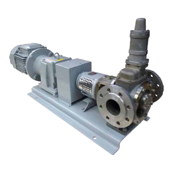
2.0 Pump description TopGear H-pumps are rotary positive displacement pumps with internal gear. They are made of stainless steel, nodular iron or cast steel. TGH-pumps are assembled from modular elements, which allows a variety of constructions: different shaft sealings (packing and/or mechanical seal), heating/ cooling jackets (steam or thermal oil), several sleeve bearings, gear and shaft materials and mounted relief valve. - Page 13 8. Jacket options around shaft seal Shaft seal without jackets Shaft seal with jacket and thread connection Shaft seal with jacket and flange connection 9. Idler bush and idler materials Idler bush in hardened steel with idler in iron CG Idler bush in carbon with idler in iron Idler bush in bronze with idler in iron HG Idler bush in ceramic with idler in iron Idler bush in hardened steel with idler in steel...
- Page 14 Example: TG H 58-80 R 2 S S BR 5 B R5 PQTC 10 11 TG H 360-150 FD R 5 O O UR 6 U R8 GS WV 10 11 13. Shaft seal arrangements (cont’d) Packing version with lantern ring PQ TC PTFE graphited packing rings PQ AW...
-
Page 15: General Technical Information
3.0 General technical information Pump standard parts Top cover Intermediate casing Pump shaft Bearing bracket Idler pin Rotor Pump cover Idler gear Pump casing Operating principle As the rotor and idler gear unmesh, an underpressure is created and the liquid enters the new created cavities. Liquid is transported in sealed pockets to the discharge side. -
Page 16: Self-Priming Operation
3.2.1 Self-priming operation TopGear pumps are self-priming when sufficient liquid is present in the pump to fill up the clearances and the dead spaces between the teeth. (For self-priming operation see also section 3.18.6.2 Piping). 3.2.2 Safety relief valve – Working principle The positive displacement principle requires the installation of a safety relief valve protecting the pump against overpressure. -
Page 17: Main Characteristics
Main characteristics The pump size is designated by the displacement volume of 100 revolutions expressed in litres (or dm ) but rounded followed by the nominal port diameter expressed in millimetres. Vs-100 n.max n.mot Q.th Q.th ∆p p.maw p.test TG H pump size (bar) (bar) (bar) -
Page 18: Pressure
Pressure For performance on pressure, three kinds of pressures must be considered: Differential pressure or working pressure (p) is the pressure on which the pump normally operates. The maximum differential pressure for all TopGear H-range pumps is 16 bar. Maximum allowable working pressure (p.m) is the pressure on which the pump casing is designed and that can been achieved occasionally when the operating pressure rises over the normal operating pressure e.g. -
Page 19: The Sound Level Of The Pump Unit
Sound power level (L The sound power L is the power emitted by the pump as sound waves and is used to compare sound levels of machines. It is the sound pressure Lp that act on a surrounding surface at distance of 1 meter. -
Page 20: Material Options
Material options Overall temperature The TG H range is designed for high temperatures. The overall temperatures for selected casing materials are shown in below table. Minimum allowable temperature (°C) Maximum allowable temperature (°C) TG H Casing materials Casing materials pump size Stainless steel (R) Carbon steel (S) Nodular iron (N) -
Page 21: Maximum Temperature Of Internals
3.10.2 Maximum temperature of internals For some material combinations the general temperature performances must be limited. The maximum allowable working temperature of internals depends on the combination of used materials and their thermal expansions and the interference fit to hold the bearing bush fixed. •... -
Page 22: Maximum Torque Of Pump Shaft And Rotor Material Combination
3.10.4 Maximum torque of pump shaft and rotor material combination The maximum allowable torque is a constant independent from speed and may not be exceeded to avoid damaging the pump i.e. pump shaft, rotor/shaft fitting and rotor teeth. Mn (nominal torque) in Nm Md (starting torque) in Nm N Rotor N Rotor... -
Page 23: Extra Clearances
3.13 Extra clearances To indicate required clearances a code of 4 digits, xxxx, is given on the order. These digits refer to the following clearance classes: C0 = Axial clearance between rotor and pump cover set at minimum C1 = Standard clearance (not indicated because standard) C2 = ~2 x standard clearance C3 = 3 x standard clearance The 4 digits indicate which clearance class is set for which part of the pump, e.g.: code 2 3 3 2... -
Page 24: Play Between Gear Teeth
3.14 Play between gear teeth TG H 2-32 3-32 6-40 15-50 23-65 58-80 86-100 185-125 360-150 Minimum (µm) Maximum (µm) Play between gear teeth 3.15 Maximum size of solid particles TG H 2-32 3-32 6-40 15-50 23-65 58-80 86-100 185-125 360-150 Size (µm) A.0500.351 –... -
Page 25: Shaft Sealings
3.16 Shaft sealings 3.16.1 Packed gland 2-32 15-50 TG H pump size 6-40 58-80 86-100 185-125 360-150 3-32 23-65 Shaft diameter Section width 5x Lantern ring width Dimensions in mm 3.16.2 Packing ring materials Most universal solution. Woven shaft packing consisting of PTFE yarns with incorporated graphite and sliding matters (yarns GORE-GFO). -
Page 26: Cartridge Mechanical Seals
Performance Maximum performance such as viscosity, temperature and working pressure depends on the make of the mechanical seal and the used materials. The following basic values can be taken into consideration. Maximum temperatures of elastomers Nitrile (P): 110°C FPM (Fluorocarbon): 180°C PTFE (solid or PTFE wrapped): 220°C... - Page 27 Built-in dimensions G=ANSI B1.20.1 Sealing face 45° 4xMd 40° Rp=ISO 7/1 Ød1 Ød4 Øda Ødb Ødc Øde Ødf 4xMd TG H pump size [mm] [mm] [mm] [mm] [mm] [mm] [mm] [mm] [mm] [mm] [mm] [mm] [mm] [mm] 2-32 4xM6 11.5 3-32 4xM6 11.5...
-
Page 28: Reverted Packing Execution For E.g. Chocolate Application
3.16.4 Reverted packing execution for e.g. chocolate application For chocolate pumping applications the PR version is designed. The pump shaft is sealed by means of packing rings and the bronze shaft bearing is placed outside the pumped medium and is designed to work as a packing gland. Because of the fact that, under normal conditions, the shaft bearing does not come into contact with the pumped medium, bronze can be used as material. -
Page 29: Triple Ptfe Lip-Seal Cartridge
3.17.5 Triple PTFE lip-seal cartridge As from the first of July 2015, this new shaft sealing option (TCL TV) is available on the TopGear GM and H range. This new shaft sealing option can be used for pumping products with a viscosity of more than 5.000 mPas as alternative for double mechanical seals omitting the need for an expensive pressurized quench system. -
Page 30: Safety Relief Valve
3.17 Safety relief valve Example V 35 - G 10 H 1. Safety relief valve = V 2. Type indicating = inlet diameter (in mm) Safety relief valve size for TG H2-32, TG H3-32, TG H6-40 Safety relief valve size for TG H15-50, TG H23-65 Safety relief valve size for TG H58-80... -
Page 31: Pressure
3.17.1 Pressure Safety relief valves are divided into 4 working pressure classes i.e. 4, 6, 10 and 16 indicating the maximum working pressure for that valve. Each class has a standard set pressure at 1 bar above the indicated maximum working pressure. The set pressure can be set lower on request never higher. Working pressure class Standard set pressure (bar) Working pressure range (bar) -
Page 32: Safety Relief Valve - Relative Adjustment
3.17.3 Safety relief valve – Relative adjustment Adjustment of the standard setting pressure is performed at the factory. Note! When testing the safety relief valve mounted on the pump, make sure the pressure never exceeds the set pressure of the valve + 2 bar. To adjust the standard opening pressure, proceed as follows: 1. -
Page 33: Sectional Drawings And Part Lists
3.17.4 Sectional drawings and part lists 3.17.4.1 Single safety relief valve 7400 7240 7030 7330 7040 7180 7100 7100 7110 7300 7310 7320 7050 7170 7010 7150 Single safety relief valve – horizontal 7360 7400 7310 7050 7180 Pos. Description Preventive Overhaul 7010 Valve... -
Page 34: Heated Spring Casing
3.17.4.2 Heated spring casing 7041 Pos. Description Preventive Overhaul 7041 Heated spring casing 3.17.4.3 Double safety relief valve 8020 8050 8020 8050 8010 8010 8040 8060 8040 8070 8030 8070 8060 8030 Double safety relief valve – horizontal Double safety relief valve – vertical Pos. -
Page 35: Installation
3.18 Installation 3.18.1 General This manual gives basic instructions which are to be observed during installation of the pump. It is therefore important that this manual is read by the responsible personnel prior to assembly and afterward to be kept available at the installation site. The instructions contain useful and important information allowing the pump/pump unit to be properly installed. -
Page 36: Indoor Installation
3.18.2.4 Indoor installation Locate the pump so that the motor can be vented properly. Prepare the motor for operation according to instructions provided by the motor manufacturer. When flammable or explosive products are pumped, a proper earthing should be provided. The components of the unit should be connected with earthing bridges to reduce the danger arising from static electricity. -
Page 37: Radial Load On Shaft End
3.18.3.2 Radial load on shaft end The shaft end of the pump shaft may be loaded in radial sense with the maximum radial force (Fr). See table. TG H pump size Fr (N) - max 2-32/3-32 6-40 15-50/23-65 1000 58-80/86-100 2000 185-125 3000... -
Page 38: Shaft Rotation For Pump With Safety Relief Valve
3.18.5 Shaft rotation for pump with safety relief valve The shaft rotation determines which port of the pump is suction and which is discharge. The relation between the shaft rotation and the suction/discharge side is indicated by the rotation arrow plate attached at the valve casing of the safety relief valve. TG 2-25 TG 23-65 1 Direction of rotation of pump shaft... -
Page 39: Suction And Discharge Pipes
3.18.6 Suction and discharge pipes 3.18.6.1 Forces and moments Note! Excessive forces and moments on the nozzle flanges derived from piping can cause mechanical damage to pump or pump unit. Pipes should therefore be connected in line, limiting the forces on the pump connections. Support the pipes and make sure they remain stress-free during operation of the pump. -
Page 40: Isolating Valves
Self-priming operation At the start sufficient liquid must be available in the pump filling up the internal clearance volume and the dead spaces, allowing the pump to build up a pressure difference. Therefore, for pumping low viscosity fluids, a foot valve with the same or larger diameter than the suction pipe must be installed or the pump can be installed without foot-valve but in U-line. -
Page 41: Heating Jackets
3.18.7.2 Heating jackets 1. S-type jackets The S-jackets are designed for use with saturated steam (max 10 bar, 180°C) or with non-dangerous media. They are provided with threaded connections Bl (see chapter 6.0 for the dimensions). The connection can be done by threaded pipes or pipe connections with sealing in the thread (conical thread applying ISO 7/1) or sealed outside the thread by means of flat gaskets (cylindrical thread applying ISO 228/1). -
Page 42: Flush/Quench Media
4. Jacket around the shaft seal Connect the supply and the return line to both connections on the intermediate casing. A drain plug is provided in the intermediate casing at the bottom side (Bg). In case of steam supply this drain can be connected to a drain line to evacuate condensed water. -
Page 43: Single Mechanical Seal
• When at a high discharge pressure packing (3000) must be relieved. Connect the suction flange via Bd or Bi. Be sure the pressure in the lantern ring area is above atmosphere pressure to avoid air sucking through the last packing rings which makes the packing running dry. •... -
Page 44: Double Mechanical Seal - Back-To-Back Arrangement
3.18.8.4 Double mechanical seal – Back-to-back arrangement • Use connection Bd or Bi as the outlet of quench media and one of the connections Bj as the inlet. • Use connection Bc as filling and air release plug (this is not possible with H2-32/H3-32 and Bd (Bi) with jackets around the shaft seal area). -
Page 45: Secondary Connections
3.18.8.6 Secondary connections Several connection types for circulation, quench or flush on shaft sealing are possible in accordance to ISO-code or to API-plan. Overview possible configurations for shaft seal circulation, quench and flushing. Shaft sealing ISO 5199 code API 610 plan 02,03,04,05,06,07,08,09,10,11,12,13 2,11,12,13,21,22,23,31,32,41,51,52,53,54,61,62 02,03,04,05,06,07,08... - Page 46 API plans 12, 22, 31, 32, 41/ ISO codes 04, 05, 08, 09 – Clean flush A flow of clean fluid to the seal chamber. The fluid can be either pumped fluid recirculating through a strainer or cyclone separator and orifice, or a clean compatible fluid injected from an external source. This media comes into contact with the pumped liquid, so it must be compatible with it.
-
Page 47: Guidelines For Assembly
API plan 52/ ISO codes 10, 03 – Circulating quench A non-pressurised barrier fluid is connected, flowing from an external source and circulating between both shaft seals. (TG H2-32/3-32) 2xBi 3.18.9 Guidelines for assembly When a bare shaft pump is delivered, the assembly with drive is the responsibility of the user. The user also must provide all necessary devices and equipment allowing a safe installation and commissioning of the pump. -
Page 48: Electric Motor Drive
3.18.9.4 Electric motor drive • Before connecting an electric motor to the mains check the current local regulations of your electricity provider as well as the EN 60204-1 standard. • Leave the connecting of electric motors to qualified personnel. Take the necessary measures to prevent damage to electrical connections and wiring. -
Page 49: Shaft Coupling
3.18.9.6 Shaft coupling Internal gear pumps demand a relatively high starting torque. During the operation shock loads are occurring due to pulsations inherent to the gear pump principle. Therefore, choose a coupling which is 1.5 times the torque recommended for normal constant load. Alignment The pump and motor shafts of complete units are accurately pre-aligned in the factory. -
Page 50: Instructions For Start-Up
3.19 Instructions for start-up 3.19.1 General The pump can be put into service when all arrangements described in chapter 3.18 Installation have been made. • Prior to commissioning, responsible operators have to be fully informed on proper operation of the pump/pump unit and the safety instructions. This instruction manual must at all times be available to the personnel. -
Page 51: Checklist - Initial Start-Up
3.19.4 Checklist – Initial start-up After thorough servicing or when the pump is to be put into service for the first time (initial start-up) the following checklist must be observed: Supply and discharge line c Suction and discharge pipes are cleaned. c Suction and discharge pipes are checked for leaks. -
Page 52: Start-Up
Protection c All guards and safety devices (coupling, rotating parts, excessive temperature) are in place and operative. c In case of pumps that may reach working temperatures of 60°C or more, ensure sufficient safety guards against occasional touching are in place. 3.19.5 Start-up When the pump is to be put into service the following checklist and procedure must be observed: c Pump is filled with liquid. -
Page 53: Trouble Shooting
3.20 Trouble shooting Symptom Cause Remedy No flow Suction lift too high • Reduce difference between Pump not priming pump and suction tank level. • Increase suction pipe diameter. • Reduce length and simplify suction pipe (use as few elbows and other fittings as possible). Also see section 3.18 Installation. - Page 54 Symptom Cause Remedy Not enough capacity Viscosity too low 17 • Increase pump speed. Attention! Do not exceed maximum speed and check NPSHr. • If necessary, install a larger pump. • • If pump is heated by means of heating jackets or electrical heating, reduce the heating input.
-
Page 55: Instructions For Re-Using And Disposal
Symptom Cause Remedy Rapid wear of the Viscosity too high 39 • Heat the pump. mechanical seal • Install a double mechanical seal Bad de-aerating/ dry running 40 • Fill pump with liquid • Check position of relief valve or top cover. Temperature too high 41 •... -
Page 56: Maintenance Instructions
Make sure that the personnel read the entire instruction manual and, in particular, indicate those sections concerning the work at hand. • SPX is not responsible for accidents and damage caused by non-compliance with the guidelines. 3.21.2 Preparation 3.21.2.1 Surroundings (on site) -
Page 57: External Cleaning
3.21.2.6 External cleaning • Keep the surface of the pump as clean as possible. This simplifies inspection, the attached markings remain visible and grease nipples are not forgotten. • Make sure cleaning products do not enter the ball bearing space. Cover all parts that must not come into contact with fluids. -
Page 58: Fluid Circuits
Never re-use flat gaskets. • Always replace the flat gaskets and elastic rings under the plugs with genuine spares from SPX. 3.21.3.4 Filter or suction strainer Any filters or suction strainers at the bottom of the suction line must be cleaned regularly. -
Page 59: Sleeve Bearings
The standard “multi-purpose” grease (consistent class NLGI-2) is suitable for temperatures up to 120°C. For higher temperatures the standard grease should be replaced by a high temperature grease (consistent class NLGI-3). This grease is, depending on the make, suitable for temperatures up to 150°C or 180°C. -
Page 60: Shaft Seals
3.21.3.7 Shaft seals A. Gland packing PO • For pumps with gland packing, regularly check the packing for leaks. A slight leakage is normal. • Regularly check connections on the lantern ring (if applicable). • If the gland packing leaks excessively or when the pump needs serve, the old packing rings must be replaced. - Page 61 B. Gland packing PQ • For pumps with gland packing, regularly check the packing for leaks. A slight leakage is normal. • Regularly check connections on the lantern ring (if applicable). • If the gland packing leaks excessively or when the pump needs serve, the old packing rings must be replaced.
-
Page 62: Front Pull-Out
C. Reverted packing PR When pumping chocolate, the packing needs to be tightened bit by bit at the (initial) start-up in order to achieve the utmost minimum of leakage, just enough to lubricate the packing rings. Excessively leaking chocolate can overheat in the packing, causing caramelisation, resulting in extra wear of the packing. -
Page 63: Designation Of Threaded Connections
1. Loosen the set screws (1480). 1480 2. Tighten the bolts (1540). 1530 3. The pump shaft with roller bearing and rotor will be pushed against the pump cover. The axial clearance is then zero. 1540 4. Install a gauge on the bearing bracket. 5. -
Page 64: Instructions For Assembly And Disassembly
Non-compliance with the instructions or neglecting warnings can damage the user or lead to severe damage to pump and/or pump unit. SPX is not liable for accidents and damage resulting from such neglect. -
Page 65: Anti-Friction Bearings
Anti-friction bearings 4.5.1 General • Never re-use a disassembled bearing or a disassembled lock plate! • For disassembly and assembly of the bearing (and coupling). use correct tools in order to inspect the pump without any shock loads. Shocks can damage the crisp material of bush bearings and mechanical seal. -
Page 66: Tg H6-40 To Tg H360-150 Disassembly
4.5.4 TG H6-40 to TG H360-150 disassembly 1. First disassemble the flexible coupling half with the aid of a coupling extractor. 2. Remove key (1570), set screws (1480), tap bolts (1540) and long screws (1530). 3. Remove the outer bearing cover (1470) and the V-seal (1490). 4. -
Page 67: Relief Valve
Relief valve • The relief valve may not be disassembled before the spring has been released completely • Before releasing the spring, measure the position of the adjusting bolt, so that the spring afterwards can be adjusted to its original opening pressure 4.6.1 Disassembly •... -
Page 68: Mechanical Seal
Mechanical seal Guidelines for assembly and adjustment of the mechanical seal – pump types GS, GG and GD. 4.7.1 General • All personnel responsible for maintenance, inspection and assembly must be adequately qualified. • Use specific instructions coming with the mechanical seal which is to be assembled/adjusted. •... -
Page 69: General Instructions During Assembly
Remark: The set ring that is delivered by SPX guarantees a reliable fixation. There is no danger it will be loosened by alternating loads. SPX cannot guarantee a reliable fixation with other set rings. -
Page 70: Adjustment Of Mechanical Seal
4.7.7 Adjustment of mechanical seal 4.7.7.1 GS – Single mechanical seal 1. Mechanical seal without set screws (e.g. Sealol type 043 and Burgmann type MG12) – Pump size TG H2-32 and TG H3-32 The mechanical seal is mounted against a shoulder ring (2090), see figure. Adjusting is not necessary if the built in length of the mechanical seal corresponds to EN12756 (DIN24960) L length. - Page 71 B. Sizes TG H6-40 to TG H360-150 The mechanical seal must always be adjusted and fixed on the pump shaft by means of set screws. For mechanical seal without set screws (e.g. Sealol, type 043 and Burgmann type MG12) a special set ring with fixing screws (3030 and 3040) must be used for adjusting the mechanical seal on the pump shaft.
- Page 72 Values for recalculation of adjusting distance X EN12756 (DIN24960) KU (short type) EN12756 (DIN24960) NU (long type) TG H pump type Shaft d [mm] B (with set ring) [mm] [mm] 1N-max 2-32/3-32 46.1 – – 6-40 35.7 34.7 44.7 42.2 15-50/23-65 42.5 36.7...
- Page 73 Thickness dimensions for composition of adjustment height X Shaft seal GS & GG For EN (DIN) KU mechanical seal For EN (DIN) NU mechanical seal Dimension A [mm] TG H TG H TG H TG H TG H TG H TG H TG H TG H...
-
Page 74: Gg - Double Mechanical Seal Tandem
4.7.7.2 GG – Double mechanical seal tandem 1. Assemble the first mechanical seal using the same procedure as a single mechanical seal, type GS (see section 4.7.7.1). 2. Fix the mechanical seal cover (2200) with 2 bolts (9030) without tightening them. Leave the gasket (2080) uncompressed. - Page 75 10. Lock the adjusting tool by means of 2 bolts (9050). 11. Tighten the screws of the mechanical seal and secure them with Loctite. 12. Remove the adjusting tool (9040) and the two bolts (9050). 13. Assemble the rotating part of the second mechanical seal (3020). Push it against the first mechanical seal and secure the fixing screws with Loctite.
-
Page 76: Gc - Mechanical Seal Cartridge
4.7.7.4 GC – Mechanical seal cartridge A. General 1. Clean the shaft and casing and check if sealing faces are in good condition. Use always a new gasket (2080) that is in good condition. Ensure that the auxiliary connection openings are in the good position and accessible for use. For exact position, see the figures and detailed instructions in the next paragraphs. - Page 77 fixing set screws G1/4 G1/4 black jig (assembly tool) DRAIN NPT1/8 Fig TN3 – View on arrow X • Remove black jig (1x) before fixation of shaft sleeve (allows shaft sleeve to rotate). 2080 3010 2500 • Remove non-coloured jigs (3x) after pump assembly and adjusting axial clearance.
- Page 78 D. Triple lip-seal cartridge The entire cartridge can be disassembled from the bareshaft pump as one single seal unit. Further disassembly of the unit requires an SPX service intervention and/or support. A.0500.351 – IM-TGH/07.02 EN (10/2015)
-
Page 79: Sectional Drawings And Part Lists
5.0 Sectional drawings and part lists How to order spares When ordering spare parts, please state: 1. Pump type and serial number (see name plate) 2. Position number, quantity and description Example: 1. Pump type: TG H58-80 R2SS BR5 BR5 PQTC Serial number: 2000-101505 2. -
Page 80: Hydraulic Part
5.1.1 Hydraulic part Pos. Description Nos./pump Preventive Overhaul 0010 pump casing - thread connection 0020 intermediate casing 0040 tap bolt 0100 top cover, complete 0400 jacket cover, on shaft seal 0410 countersunk screw plug PQ version 0460 plug Gx version 0600 idler + bush, complete 0700 rotor + shaft, complete 0710 bush bearing, on shaft... -
Page 81: S-Jacket Options
5.1.4 S-jacket options 5.1.4.1 S-jacket on pump cover Nos./ Pos. Description Preventive Overhaul pump 0200 jacket cover 0220 0210 tap bolt 0200 0220 gasket 0230 cap head screw 0230 0210 0430 5.1.4.2 S-jacket around shaft seal 0440 0420 0470 Nos./ Pos. -
Page 82: Single Mechanical Seal - Gs
5.1.5.2 Single mechanical seal – GS 2220 Nos./ 2210 Pos. Description Preventive Overhaul pump 2080 gasket 3010 2090 support ring (optional) 2090 2200 seal cover 2210 2200 2220 tap bolt 2080 3010 mechanical seal 5.1.5.3 Double mechanical seal tandem – GG 2420 Nos./ Pos. -
Page 83: Tg H6-40 To Tg H360-150
TG H6-40 to TG H360-150 For food applications * 1080 1101 0100 1090 1050 1060 For food applications * 1102 1100 1100 0010 1040 1030 0600 4000 1240 0040 1230 1210 1220 0720 1200 1570 0700 0020 1480 0710 1520 1490 1560 1550... -
Page 84: Hydraulic Part
5.2.1 Hydraulic part Pos. Description H6-40 H15-50 H23-65 H58-80 H86-100 H185-125 H360-150 Preventive Overhaul 0010 pump casing 0020 intermediate casing 0040 tap bolt 0100 top cover, complete 0600 idler + bush, complete 0700 rotor + shaft, complete 0710 bush bearing, on shaft 0720 set screw 1030 plug 1040 sealing ring... -
Page 85: Flange Connection Options
5.2.3 Flange connection options Pos. Description Nos./pump Preventive Overhaul 0010 pump casing 0010 A.0500.351 – IM-TGH/07.02 EN (10/2015) -
Page 86: Jacket Options
5.2.4 Jacket options 5.2.4.1 S-jacket on pump cover 0220 0200 0250 0240 0230 0210 Pos. Description H6-40 H15-50 H23-65 H58-80 H86-100 H185-125 H360-150 Preventive Overhaul 0200 jacket cover, on front tap bolt 0210 cap head screw 0220 gasket cap head screw 0230 tap bolt 0240 plug... -
Page 87: T-Jackets With Flange Connections On Pump Cover
5.2.4.3 T-jackets with flange connections on pump cover 0310 0300 0320 0220 0200 0250 0240 0230 0210 Pos. Description H6-40 H15-50 H23-65 H58-80 H86-100 H185-125 H360-150 Preventive Overhaul 0200 jacket cover, on front tap bolt 0210 cap head screw 0220 gasket cap head screw 0230 tap bolt... -
Page 88: T-Jackes With Flange Connections Around Shaft Seal
5.2.4.4 T-jackes with flange connections around shaft seal 0420 0400 0410 0510 0500 0520 0440 0430 Pos. Description H6-40 H15-50 H23-65 H58-80 H86-100 H185-125 H360-150 Preventive Overhaul 0400 jacket cover, on shaft seal 0410 cap head screw 0420 gasket 0430 plug 0440 sealing ring 0500 welding neck flange 0510 gasket... -
Page 89: Shaft Seal Options
5.2.5 Shaft seal options 5.2.5.1 Packing rings PQ with lantern ring Nos./ Pos. Description Preventive Overhaul pump 2000 stuffing box housing 2050 2070 2010 gasket 2060 2020 lantern ring, split 2040 2030 tap bolt 3000 2040 gland 2020 2050 2060 stud bolt 2010 2070... -
Page 90: Cartridge Mechanical Seal - Gc
5.2.5.4 Cartridge mechanical seal – GC 2080 3010 2500 Nos./ Pos. Description Preventive Overhaul pump 2080 gasket 2500 tap bolt cartridge 3010 mechanical seal 5.2.5.5 Double mechanical seal tandem – GG Nos./ Pos. Description Preventive Overhaul pump 2080 2080 gasket 2200 seal cover 2400 2210 pin... -
Page 91: Cartridge Mecanical Seal - Lct Tv (Lct Xx)
5.2.5.7 Cartridge mecanical seal - LCT TV (LCT XX) 2800 2050 2030 2860 2810 3080 3070 3060 2820 2830 2850 2840 2870 2000 2080 2010 H15-50 H58-80 H185-125 Pos. Description H6-40 Preventive Overhaul H23-65 H86-100 H360-150 2000 stuffing box 2010 gasket 2030 tap bolt for seal 2050 pin 2080 gasket... -
Page 92: Reverted Packing - Chocolate Version
5.2.5.7 Reverted packing – Chocolate version TG GM 6-40 to TG GM 23-65 TG GM 58-80 to TG GM 360-150 2140 2130 2140 2120 2160 2130 2050 1210 1220 1230 1240 2020 2160 2060 2110 2120 2150 2050 2070 2100 2170 2020 2110... -
Page 93: Dimensional Drawings
6.0 Dimensional drawings Standard pump 6.1.1 TG H2-32 to TG H3-32 TG H2-32 TG H3-32 G 1 1/4 G 1/4 G 1/8 G 1/4 Rp 1/8 Rp 1/8 4xøvd Rp 3/8 5 h9 14 j6 17.5 ISO/R775 A.0500.351 – IM-TGH/07.02 EN (10/2015) -
Page 94: Tg H6-40 To Tg H360-150
6.1.2 TG H6-40 to TG H360-150 ma ze Bd Bj 4xøvd ISO/R775 H6-40 H15-50 H23-65 H58-80 H86-100 H185-125 H360-150 G 1/4 G 1/4 G 1/4 G 1/2 G 1/2 G 1/2 G 3/4 G 1/4 G 1/4 G 1/4 G 1/4 G 1/4 G 1/4 G 1/2... -
Page 95: Flange Connections
Flange connections 6.2.1 TG H2-32 to TG H3-32 øak TG H2-32 TG H3-32 ac PN16/25/40 ac PN20 ac PN50 98.5 ad PN16/25/40 ad PN20 ad PN50 ak PN16/25/40 4xd18 ak PN20 4xd16 ak PN50 4xd18 am PN16/25/40 am PN20 am PN50 33.5 6.2.2 TG H6-40 to TG H360-150... -
Page 96: Jackets
Jackets 6.3.1 TG H2-32 and TG H3-32 Jackets for pump cover and thread connection, and jacket around shaft seal and thread connection (SS) 2xBl 2xBf Jackets for pump cover and No jackets for pump cover but thread connection without jacket around shaft seal and jacket around shaft seal and thread connection (OS) thread connection (SO) -
Page 97: Tg H6-40 To Tg H360-150
6.3.2 TG H6-40 to TG H360-150 Jackets for pumpcover and thread connection and jacket around shaft seal and thread connection (SS) 2xBl 2xBf Jackets for pump cover and flange connection and jacket around shaft seal and flange connection (TT) 2xCf 2xCf Jackets for pump cover and No jackets for pump cover but... -
Page 98: Safety Relief Valves
Safety relief valves 6.4.1 Single safety relief valve TG H2-32 TG H3-32 TG H6-40 TG H15-50 TG H23-65 TG H58-80 TG H86-100 TG H185-125 TG H360-150 TG H2-32 TG H6-40 TG H15-50 TG H23-65 TG H58-80 TG H86-100 TG H185-125 TG H360-150 TG H3-32 –... -
Page 99: Double Safety Relief Valve
6.4.2 Double safety relief valve TG H15-50 TG H23-65 TG H58-80 TG H86-100 TG H185-125 TG H15-50 TG H23-65 TG H58-80 TG H86-100 TG H185-125 – – – – – A.0500.351 – IM-TGH/07.02 EN (10/2015) -
Page 100: Heated Safety Relief Valve
6.4.3 Heated safety relief valve TG H15-50 TG H23-65 TG H58-80 TG H86-100 TG H185-125 TG H360-150 TG H15-50 TG H23-65 TG H58-80 TG H86-100 TG H185-125 TG H360-150 G 1/2 G 1/2 G 1/2 G 1/2 G 1/2 G 1/2 –... -
Page 101: Bracket Support
Bracket support 2xvt TG H2-32 TG H6-40 TG H15-50 TG H23-65 TG H58-80 TG H86-100 TG H185-125 TG H360-150 TG H3-32 Weights – Mass Version Mass Weight H2-32 H3-32 Pump (without jackets) PO/PQ GG/GD/GC Front-Pull out (pump cover+idler) Back-Pull out (shaft+interm.casing+bracket) Screw on flanges (supplement) - Page 102 Declaration of Compliance for food contact materials Manufacturer SPX Flow Technology Belgium NV Evenbroekveld 2-6 BE-9420 Erpe-Mere Belgium We hereby certify the compliance of the materials coming into contact with food during the intended use with the general requirements as of the date of this Declaration of Regulation (EC) No 1935/2004 of 27 October 2004 on materials and articles intended to come into contact with food and repealing Directives 80/590/EEC and 89/109/EEC.
- Page 103 A.0500.351 – IM-TGH/07.00 EN (10/2015)
- Page 104 20/10/2010 Antwerpen - Anvers - Antwerp Boombekelaan 3 B-2660 Hoboken België - Belgique - Belgium tel. +32-3 829 26 11 fax. +32-3 828 39 59 Conformiteitsattest EU1935/2004 voedingscontact Attestation de conformité CE 1935/2004 contact avec des denrées alimentaires Certificate of compliance with EC1935/2004 food contact Omschrijving RX FLOWTITE®...
- Page 105 A.0500.351 – IM-TGH/07.00 EN (10/2015)
- Page 106 A.0500.351 – IM-TGH/07.00 EN (10/2015)
- Page 107 A.0500.351 – IM-TGH/07.00 EN (10/2015)
- Page 108 A.0500.351 – IM-TGH/07.00 EN (10/2015)
- Page 110 P: +32 (0)53 60 27 15 F: +32 (0)53 60 27 01 E: johnson-pump.be@spxflow.com SPX reserves the right to incorporate our latest design and material changes without notice or obligation. Design features, materials of construction and dimensional data, as described in this bulletin, are provided for your information only and should not be relied upon unless confirmed in writing.
Need help?
Do you have a question about the TopGear H Series and is the answer not in the manual?
Questions and answers