
Subscribe to Our Youtube Channel
Related Manuals for Kirisun DM588


Summary of Contents for Kirisun DM588
- Page 1 Professional wireless communication system solution supplier DM588 SERVICE MANUAL ShenZhen Kirisun Communications Co.,Ltd. V191225...
-
Page 2: Table Of Contents
DM588 Service Manual Contents 1. Overview ............................1 1.1. Range of Application ........................1 1.2. Safety Precaution ........................1 1.3. Maintenance Service ........................1 2. External View and Keys ........................2 2.1. External View ..........................2 2.2. LED Indicator ..........................2 ............................. - Page 3 ....................41 Appendix 2 Material List (Electronic Part) Table 1 Material List of Main Board DM588-01 (136MHz-174MHz) ............ 41 Table 2 Material List of Main Board DM588-02 (400MHz-470MHz) ............ 58 Table 3 Material List of Main Board DM588-08 (400MHz-480MHz) ............ 73 Table 4 Material List of DM588 LCD Board ..................
-
Page 4: Overview
1. Overview 1.1.Range of Application This manual is intended for the maintenance of the DM588 digital mobile radio and for use by the engineers and professional technicians, who have received training from Kirisun. The information in this manual might change with technology improvement. To obtain the latest information, please contact Kirisun or your local dealer. -
Page 5: External View And Keys
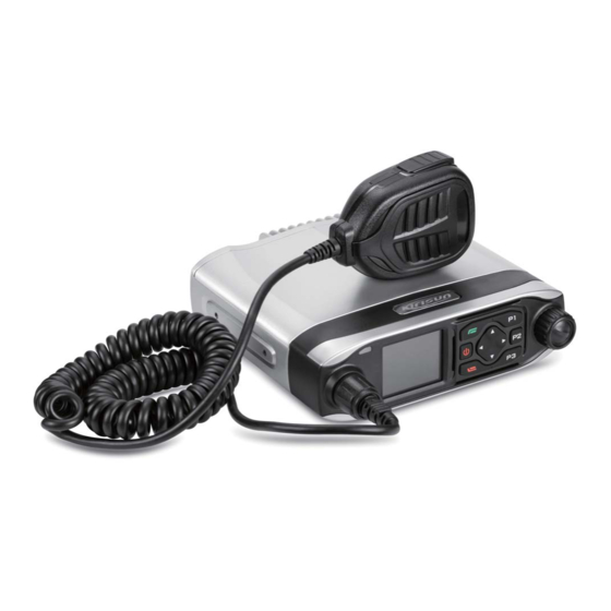
DM588 Service Manual 2. External View and Keys 2.1.External View Part Name Part Name LED Indicator Speaker Menu/OK Key Up/Down/Left/Right Key Hand Micro (and Programming Cable) Programmable Keys (P1~P3) Interface Emergency Alarm Key LCD Screen On/Off Key Back Key Volume/Channel Knob... -
Page 6: Basic Operation
DM588 Service Manual Orange Light Flashing In call hold state under digital mode, and exit when hold time out Red Light Flashing Fast CPS reading radio parameters Green Light Flashing Fast CPS programming radio parameters 3. Basic Operation 3.1.Powering On/Off To power on the radio, hold down the On/Off key until the LCD screen is on. -
Page 7: Circuit Description
DM588 Service Manual 4. Circuit Description 4.1.Schematic Circuit Diagram of Main Board 4.2.Tx Circuit The TX circuit includes an RF power amplification circuit, a low pass filter circuit and an automatic power control circuit. RF Power Amplification Circuit Transmitting signals TX VCO are buffered and amplified by the Q7, Q8, Q9 and then the pre-drive amplifier Q18 to generate strong enough driving power signals, and then amplified by the last-stage amplifier Q29. -
Page 8: Rx Circuit
DM588 Service Manual using a microstrip to reduce loss of output power caused by impedance mismatching. Then, transmitting signals go through the TX/RX switch (composed of the D14, D15, D16 and D17) and enter the low-pass filter (LPF). Low-Pass Filter (LPF) Circuit The low-pass filter for inhibiting harmonic wave is a high-order Chebyshev filter composed of a lumped parameter inductance and a capacitance. -
Page 9: Frequency Synthesis Circuit
DM588 Service Manual 4.4.Frequency Synthesis Circuit The frequency synthesis circuit is composed of the phase-locked loop (PLL) chip LMX2571, a loop filter (LPF), a voltage-controlled oscillator (VCO) and a feedback network. To the LMX2571, a work clock is provided by the active resonator U9 and configuration data is provided by the master chip LT1901. -
Page 10: Others
DM588 Service Manual The radio is powered by a car battery, and the baseband circuit and the RF circuit are powered independently. A protection unit at the front end of the power supply detects overvoltage and overcurrent to ensure safety. - Page 11 DM588 Service Manual Pin NO. Port NO. Network Name Description GPIO_D17 RED_LED Enable red indicator GPIO_D18 GREEN_LED Enable green indicator AA18 GPIO_D22 SWITCH_A Channel encoding switch AB17 GPIO_D23 SWITCH_B Channel encoding switch AA17 GPIO_D24 ENTER Channel encoding switch AA15 GPIO_D30/D93...
-
Page 12: Control Panel
DM588 Service Manual Pin NO. Port NO. Network Name Description L22/IC2. ADCIN RSSI Field intensity detection AIN2 TEMPERATUR IC2.AIN3 TEMPERATURE Temperature detection IC2.AIN0 BATDET BATDET Battery voltage detection PRST---RSTO P6---F17 PRST F16---E1 OSCEN--PMU_ OSCEN OSCEN GPIO_D44 SECRET_RST Reset encryption chip... -
Page 13: Feature Description And Parameter Settings
DM588 Service Manual Backlight Control USB+ Power Output (7~12V) Ground Power Ground Power Supply The main board provides two routes of power supply for the control panel: one is DC3.3V for the key scan module and LCD module, and the other is DC13.2V for the hand microphone, LED screen and backlight lamp. -
Page 14: Zones
DM588 Service Manual Scan List Each channel can be related to one scan list though programming by your dealer. The radio can scan only on a channel related to a scan list. Each scan list contains up to 16 channels (including the current channel), including analogue and digital channels. -
Page 15: Tot (Time-Out-Timer)
DM588 Service Manual Microphone Gain Microphone gain is the value based on which an audio level is amplified. You can adjust volume by setting a microphone gain. The higher the gain is, the higher the volume will be. Note: A too high gain might result in speech distortion. -
Page 16: Parameter Settings
DM588 Service Manual Emergency alarm: A non-speech signal sent from one radio to others in the group to trigger an alarm alert on these radios. Alarm call: A call of a higher call priority than a common call is, which guarantees communication under emergency. -
Page 17: Assembly And Disassembly
DM588 Service Manual 6. Assembly and Disassembly This radio is sophisticated with small and precise mechanical structures. Please be careful while assembling or disassembling the radio. 6.1.Separating RF Unit and Control Panel To separate the RF part and the control panel, take the following steps. -
Page 18: Disassembling Main Unit
DM588 Service Manual 6.2.Disassembling Main Unit To disassemble the main unit, take the following steps. 1. Screw down the eight M3*6 cross recessed mushroom-head machine screws fastening the main board, unweld antenna connector using a soldering iron, and unplug the GPS and Bluetooth cable connectors. -
Page 19: Disassembling Front Part
DM588 Service Manual 6.3.Disassembling Front Part To disassemble the front part of the radio, take the following steps. 1. Remove the Volume/Channel knob and knob circlip, and screw down the M6*0.35 switch nut. 2. Screw down the five ST2*5 torx machine screws fastening the front and rear housings. -
Page 20: Explosion Diagram
7MBR-4304-05A-W0A Rubber plug for M50_SIM card 7MBP-4291-01B-W0 DM588 plastic front housing 7MBR-4304-03A-WC M50 light pipe 4PC7-4099B-A LCD screen Waterproofing cover ring of DM588 hand 7MBR-4291-01A-W3 microphone connector 7MBS-4304-02A-W M50_LCD screen holder 3CC3-16MB-Y10J KME231 aerial-plug socket 6SS2-4291-HFB DM588 LCD board nesting... -
Page 21: Debugging
DM588 Service Manual Material Code Specifications 7MBS-4304-03B-W M50 speaker clamping ring 7MBR-4291-02A-W3 DM588 waterproof ring of panel 4SS7-3520-016-700 Speaker 7MBR-4304-04A-W0 M50 speaker seal ring 7SMF-025050M-MHYB-B R M2.5*5 torx mushroom-head machine screw 7SMF-025050M-MHYB-B R M2.5*5 torx mushroom-head machine screw 7NRC-040050204-LJ M2.0*5+4 hexagon copper post... -
Page 22: Debugging
DM588 Service Manual 7.2.Debugging Tx Part Measurement Tool and Method Item Environment Index Requirement Test Device Test Point Tool Method Program the radio, download audio At low Detect VCO voltage in source, switch between low and high frequency: >=0.5V; 1. VCO test Multimeter mode. - Page 23 DM588 Service Manual Measurement Tool and Method Item Environment Index Requirement Test Device Test Point Tool Method 1) Run the debugging software on the PC, and set the tester to adjustment mode; 2) Double click [High Power], and click [Low Frequency];...
- Page 24 DM588 Service Manual Measurement Tool and Method Item Environment Index Requirement Test Device Test Point Tool Method 1) Run the debugging software on the PC, and set the tester to adjustment mode; 2) Double click [Analogue MOD1], Connect and click [Low Frequency];...
- Page 25 DM588 Service Manual Measurement Tool and Method Item Environment Index Requirement Test Device Test Point Tool Method Digital 1) Run the debugging software on the 4FSK ERROR<5% MOD1 PC, and set the tester to adjustment 1944±100Hz mode. 2) Go to the DMR test interface. Set...
- Page 26 DM588 Service Manual Measurement Tool and Method Item Environment Index Requirement Test Device Test Point Tool Method After debugging the TX modulation sensitivity, 1) Set the tester to TX state, 300~3kHz to the filter, and audio output to 1kHz@modulation Connect sensitivity;...
- Page 27 DM588 Service Manual Measurement Tool and Method Item Environment Index Requirement Test Device Test Point Tool Method After debugging the TX modulation sensitivity, 1) Set the tester to TX state, 300~3kHz to the filter, and audio output to Connect 1kHz@modulation antenna 1) W: >40dB (wide...
- Page 28 DM588 Service Manual Measurement Tool and Method Item Environment Index Requirement Test Device Test Point Tool Method After debugging the TX modulation sensitivity, 1) Set the tester to Adjacent Ch Power Test state, Ch Offset to W: 25kHz (wide band)/N: 12.5kHz (narrow band),...
- Page 29 DM588 Service Manual Measurement Tool and Method Item Environment Index Requirement Test Device Test Point Tool Method (CE standard compliant) 1) Connect the test interface of the FSU Connect spectrum analyzer to a antenna 30dB attenuator interface of the (power: > 10W);...
- Page 30 DM588 Service Manual Measurement Tool and Method Item Environment Index Requirement Test Device Test Point Tool Method 1) Power off the radio. Adjust the output voltage of the DC power supply to the standard test voltage of the radio, and...
- Page 31 DM588 Service Manual Measurement Tool and Method Item Environment Index Requirement Test Device Test Point Tool Method 1) Run the debugging software on Connect the PC, and set the tester to 1) Set the tester to RX antenna adjustment mode;...
- Page 32 DM588 Service Manual Measurement Tool and Method Item Environment Index Requirement Test Device Test Point Tool Method 1) Run the debugging software on 1) Set the tester to RX the PC, and set the tester to state; adjustment mode; 2) Set RF Gen Freq = 2) Disable Squelch Level 1 for 4.
- Page 33 DM588 Service Manual Measurement Tool and Method Item Environment Index Requirement Test Device Test Point Tool Method 1) Run the debugging software on 1) Set the tester to RX the PC, and set the tester to state; adjustment mode; 2) Set RF Gen Freq = 2) Disable Squelch Level 9 for 6.
- Page 34 DM588 Service Manual Measurement Tool and Method Item Environment Index Requirement Test Device Test Point Tool Method 1) Run the debugging software on 1) Set the tester to RX the PC, and set the tester to state; adjustment mode; 2) Set RF Gen Freq = 2) Disable Squelch Level 1 for 8.
- Page 35 DM588 Service Manual Measurement Tool and Method Item Environment Index Requirement Test Device Test Point Tool Method 1) Run the debugging software on 1) Set the tester to RX the PC, and set the tester to state; adjustment mode; 2) Set RF Gen Freq = 2) Disable Squelch Level 9 for 10.
- Page 36 DM588 Service Manual Measurement Tool and Method Item Environment Index Requirement Test Device Test Point Tool Method 1) Run the debugging software on 1) Set the tester to RX the PC, and set the tester to state; adjustment mode; 2) RF Gen Freq = 2) Double click [Narrow-Band RSSI 12.
- Page 37 DM588 Service Manual Measurement Tool and Method Item Environment Index Requirement Test Device Test Point Tool Method 1) Run the debugging software on the PC, and set the tester to 1) Set the tester to RX adjustment mode; state; 2) Double click [Wide-Band RSSI 5], 2) Set RF Gen Freq = 14.
- Page 38 DM588 Service Manual Measurement Tool and Method Item Environment Index Requirement Test Device Test Point Tool Method 1) Set the tester to RX Connect state; antenna 2) Set RF Gen Freq to a interface of the medium frequency, set radio to RF...
- Page 39 DM588 Service Manual Measurement Tool and Method Item Environment Index Requirement Test Device Test Point Tool Method 1) Power on the radio and disable TX. Connect the 1) Run the debugging software on RF IN interface of the the PC, and set the tester to radio to the RF OUT adjustment mode;...
-
Page 40: General Specifications
DM588 Service Manual 8. General Specifications General Specification UHF1: 400-470MHz Frequency Range VHF1: 136-174MHz Channel Capacity 1024 Channel Spacing 12.5kHz/25kHz Environment Index Operating Temperature -30°C ~+60°C Storage Temperature -40°C ~+85°C Waterproofing and IP54 Dustproofing IEC 61000-4-2 (L4) ESD Protection ±8kV (contact discharge) ±15kV (air discharge) -
Page 41: Devices For Maintenance And Test
DM588 Service Manual TTFF (Cold Start) < 1 min TTFF (Hot Start) < 10s Horizontal Positioning < 10m Precision 9. Devices for Maintenance and Test Device Specification Frequency range: 10MHz~3GHz Standard Signal Generator Modulation: Frequency modulation and external modulation Output: -127dBm/0.1uV to > -47dBm/1mV Input impedance: 50Ω... - Page 42 DM588 Service Manual Failure Description Troubleshooting Replace the fuse. A. Make sure the channels the both radios communicate on are of the same frequency. Communication failure B. The radios use different CTCSS/DCS signaling codes. Set the same one via PC.
-
Page 43: Appendix 1 Abbreviations
DM588 Service Manual Appendix 1 Abbreviations Amplify, amplifier Antenna Aautomatic power control Band pass filter CTCSS Continuous tone control squelch system Digital code squelch DEMOD Demodulation E2PROM Electrically erasable programmable read only memory High pass filter Instantaneous deviation control Intermediate frequency... -
Page 44: Appendix 2 Material List (Electronic Part)
DM588 Service Manual Appendix 2 Material List (Electronic Part) Table 1 Material List of Main Board DM588-01 (136MHz-174MHz) Material NO Material Name Specifications Component NO SMD nesting for Main board DM588-01 (with 6SS1-4324-HMC2 GPS module, without LT1901 chip based, 136~174 MHz... - Page 45 DM588 Service Manual Material NO Material Name Specifications Component NO C7,C11,C20,C25,C26,C398,C463,C94,C99,C105, C108,C157,C383,C214,C231,C235,C239,C245,C 280,C282,C295,C297,C304,C330,C337,C339,C55 1,C49,C369,C372,C379,C389,C390,C396,C407,C 2CC1-10-X7R500-1 R multi-layer chip 1005, 1000P±10%, 50V, X7R 408,C409,C410,C411,C412,C438,C51,C62,C392, capacitor C417,C420,C422,C431,C432,C481,C487,C494,C 501,C43,C305,C388,C397,C400,C405,C406,C434 ,C446,C447,C513,C514,C515,C516,C517,C522,C 548,C464,C512,C520,C523,C524,C559 2CC1-10-X7R500-1 R multi-layer chip C21,C93,C97,C98,C178,C183,C218,C220,C232,C 1005, 10nF±10%, 50V, X7R capacitor 233,C238,C253,C293,C471,C564,C579,C224 2CE1-VS250-101M SMD aluminum SMD-6.3x7.7mm, 100uF/25V...
- Page 46 DM588 Service Manual Material NO Material Name Specifications Component NO 100M 3*3*1.2MM 1TF1-SSM3K15AF R SMD field effect SSM3K15AFS (D1) Q10,Q11,Q20 transistor R SMD field effect 1TF1-ST2301 ST2301A, SOT-23 Q17,Q23,Q102 transistor 1TT1-DTA144EE R SMD triode Digital triode DTA144EE-SMD 1TT1-DTC144EE R SMD triode...
- Page 47 DM588 Service Manual Material NO Material Name Specifications Component NO 2CC1-10-C0G500-5 R multi-layer chip 1005, 5P±0.25P, 50V, C0G C75,C145,C212,C229 capacitor C76,C324,C325,C86,C89,C116,C131,C138,C174, 2CC1-10-C0G500-1 R multi-layer chip C189,C192,C546,C335,C336,C341,C342,C343,C 1005, 100P±5%, 50V, C0G capacitor 344,C345,C347,C353,C354,C394,C395,C429,C43 2CC1-10-C0G500-1 R multi-layer chip 1005, 10P±0.5P, 50V, C0G...
- Page 48 DM588 Service Manual Material NO Material Name Specifications Component NO 1608, 22nH±5% 2LL1-16-22NJB Multi-layer chip inductor (SDCL1608C22NJTDF), SunLord R21,R170,R171,R308,R309,R34,R140,R142,R76, R86,R92,R137,R220,C358,R169,R326,FB21,FB2 1005, 0Ω 2RS1-10-000O R chip resistor 2,FB23,R157,R179,R183,R184,R185,FB24,R186, R187,R283,R284,FB34,FB35,FB36,FB37,R152,R 274,R275,R276,R300,C555,R272,R211 1005, 12Ω±5% 2RS1-10-120J Chip resistor R23,R74 USTAR, U10-U7, 2.2-2.4mm high, lead...
- Page 49 DM588 Service Manual Material NO Material Name Specifications Component NO capacitor 2CC1-10-C0G500-6 R multi-layer chip 1005,68P±5%,50V,C0G C121 capacitor 2CC1-10-C0G500-3 Multi-layer chip 1005,30P±5%,50V,C0G C122,C136,C185,C186,C265,C266,C289 capacitor 2CC1-10-C0G500-1 R multi-layer chip 1005,120P±5%,50V,C0G C123 capacitor 2CC1-10-C0G500-1 R multi-layer chip 1005,1P±0.25P,50V,C0G C124 capacitor 2CC1-10-C0G500-2 Multi-layer chip 1005,2P±0.1P,50V,C0G...
- Page 50 DM588 Service Manual Material NO Material Name Specifications Component NO Brand: Texas Instruments; model: 1IS1-LMX2571NJK Phase-locked loop IC LMX2571NJKT; encapsulation: 36PIN WQFN 1TC1-UMC4 R SMD Darlington tube UMC4, NPN/PNP IC10,IC14 1IS1-OPA348 Operational amplifier IC Model: OPA348; encapsulation: SC70-5 IC11,IC12 2520, 0.47μH±10%, ceramic core...
- Page 51 DM588 Service Manual Material NO Material Name Specifications Component NO 2RS1-10-392J R chip resistor 1005, 3.9K±5% R43,R46,R48,R108 2RS1-10-562J R chip resistor 1005, 5.6K±5% 2RS1-10-183J R chip resistor 1005, 18K±5% R50,R72 2RS1-10-273J R chip resistor 1005, 27K±5% 2RS1-10-124J R chip resistor 1005, 120K±5%...
- Page 52 DM588 Service Manual Material NO Material Name Specifications Component NO capacitor 2CC1-10-C0G500-6 R multi-layer chip 1005, 6P±0.25P, 50V, C0G C210,C226,C300 capacitor 2CC1-16-C0G500-4 R multi-layer chip 1608, 470P±5%, 50V, C0G C602 capacitor 2CC1-10-X7R500-1 Multi-layer chip 1005, 18nF±10%, 50V, X7R C223 capacitor...
- Page 53 DM588 Service Manual Material NO Material Name Specifications Component NO Wire diameter φ0.9, inner diameter 2LH1-R903R0-L03- R SMD air core φ3.0, 2.5-wind, reverse winding, lead L113 inductor free 2012, 220nH±5%, ceramic core 126 2LW1-20UC-221J R SMD wire wound L316 (LQN21AR22J/LQW2BHNR22J03L)
- Page 54 DM588 Service Manual Material NO Material Name Specifications Component NO 2CC1-10-C0G500-2 R multi-layer chip 1005, 27P±5%, 50V, C0G C290,C302 capacitor 2CC1-10-C0G500-3 R multi-layer chip 1005, 39P±5%, 50V, C0G C301 capacitor 1608, 0Ω 146 2RS1-16-000O R chip resistor L43,L55,L66 R SMD wire wound 2012, 27nH±5%, ceramic core...
- Page 55 DM588 Service Manual Material NO Material Name Specifications Component NO 1005, 300Ω±5% 160 2RS1-10-301J R chip resistor R113,R114 161 2RS1-10-105J R chip resistor 1005, 1M±5% R117,R162 1005, 51Ω±5% 162 2RS1-10-510J Chip resistor R118 163 2RS1-10-363J R chip resistor 1005, 36K±5%...
- Page 56 DM588 Service Manual Material NO Material Name Specifications Component NO 182 2RS1-10-304J R chip resistor 1005, 300K±5% R181 5XT1-MC146-32R7 E SMD ceramic 32.768KHZ, MC-146, 12.5PF, 20PPM, X301 resonator lead free 184 1IS1-LTJIAMI Encryption chip LTJIAMI, for model DP585 IC18 FLASH IC, for burning software of model...
- Page 57 12.2880MHz±1.5PPm, -40°C~+85°C, 2520 oscillator FP520 FP540 2.5*2.0*0.8mm WM8758CB, 32-pin, QPN 208 1IS1-WM8758B CODEC chip encapsulation, 5*5*0.9MM, lead free, for models P520, FP560 and DM588 2CC1-16-C0G500-5 R multi-layer chip 1608, 56P±5%, 50V, C0G C560,R334 capacitor 1608, 150Ω±5% 210 2RS1-16-151J R chip resistor...
- Page 58 DM588 Service Manual Material NO Material Name Specifications Component NO 2CC1-16-X7R500-1 R multi-layer chip 1608, 10nF±10%, 50V, X7R C569,C571 capacitor 2CC1-16-C0G500-1 R multi-layer chip 1608, 150P±5%, 50V, C0G C570,C572 capacitor 2CC1-28-C0G1000- High-Q capacitor, 1111 encapsulation, 120pF C573,C574 121D high-voltage 2CC1-16-C0G500-1 R multi-layer chip 1608,12P±5%,50V,C0G...
- Page 59 DM588 Service Manual Material NO Material Name Specifications Component NO 2RT1-NCP18WF10 SMD thermistor 1608, NCP18WF104J03RB R333 4J03RB 1608, 220Ω±5% 228 2RS1-16-221J R chip resistor R336,R341 For model DM588VHF\DP585VHF, 5OC1-50R0-DSB32 SMD crystal oscillator, KDS, DSB321SDN, 50.4MHz, 0.5ppm, -2509 -40~+85°C, 3.2*2.5*0.9mm 230 2RS1-16-823J R chip resistor 1608, 82K±5%...
- Page 60 DM588 Service Manual Material NO Material Name Specifications Component NO 239 2RS1-10-223J R chip resistor 1005, 22K±5% 1608, 33Ω±5% 240 2RS1-16-330J R chip resistor Encryption chip license 241 1IS1-LTJIAMI-A Encryption chip license fee fee (for model DP58X) 2CC1-20-C0G500-2 Multi-layer chip 2012, 220P±5%, 50V, C0G...
- Page 61 DM588 Service Manual Table 2 Material List of Main Board DM588-02 (400MHz-470MHz) Material NO Material Name Specifications Component NO SMD nesting for main 6SS1-4291-HMC2 board DM588-02 (with LT1901 scheme, 400~470 MHz GPS module) C1,C2,C28,C29,C30,C31,C32,C35,C307,C403,C4 04,C448,C527,C530,C533,C535, 2CC1-20-X5R160-1 Multi-layer chip 2012, 10uF±10%, 16V, TAIYO,...
- Page 62 DM588 Service Manual Material NO Material Name Specifications Component NO 79,C389,C390,C396,C407,C408,C409,C410,C411 ,C412,C438,C51,C62,C392,C417,C420,C422,C43 1,C432,C481,C487,C494,C501,C43 2CC1-10-X7R500-1 R multi-layer chip C21,C178,C183,C218,C220,C232,C233,C238,C2 1005, 10nF±10%, 50V, X7R capacitor 53,C293,C564,C579,C224 2CE1-VS250-101M SMD aluminum SMD-6.3x7.7mm, 100uF/25V C69,C357,C493,C495 0607D electrolytic capacitor 1DR1-NSR1020MW SMD Schottky barrier NSR1020MW2T1G, lead free...
- Page 63 DM588 Service Manual Material NO Material Name Specifications Component NO encapsulation R1,R223,R172,R173,R28,R32,R39,R50,R51,R214 ,R77,R109,R229,R175,R176,R177,R178,R231,R7 2RS1-10-103J R chip resistor 1005, 10K±5% ,R9,R291,R292,R293,R294,R315,R192,R195,R22 4,R269,R298,R197,R200,R210,R230,R277,R278, R279,R322,R323 2RE1-10-6802 Precise SMD resistor 1005, 68K±1% 2RE1-10-1602 Precise SMD resistor 1005, 16.2K±1% R5,R6,R8,R147,R233,R258,R97,R144,R272,R329 2RS1-10-102J R chip resistor 1005, 1K±5%...
- Page 64 DM588 Service Manual Material NO Material Name Specifications Component NO C340,C346,C349,C359,C437,C549,C550,C423,C 424,C425,C426,C427,C428,C441,C443,C455,C43 3,C435,C442,C449,C450,C453,C454,C457,C458, C461,C386,C387,C436,C451,C478,C479,C485,C 491,C492,C498,C499,C505,C506,C507,C42,C518 ,C519,C456,C544,C545 2CC1-10-C0G500-1 R multi-layer chip 1005, 13P±5%, 50V, C0G C80,C122,C268 capacitor FB17,FB20,FB41,FB42,FB43,FB5, 5FE1-CB100505-10 1005, 1KΩ [MADE IN CHINA] SMD EMI filter FB6,FB7,FB8,FB9,FB10,FB25,R38,FB13,FB14,FB 15,FB18,FB46,FB33,FB51 1IS1-XC6209F332 SMD voltage regulator 3.3V,SOT-23-5,300Ma,...
- Page 65 DM588 Service Manual Material NO Material Name Specifications Component NO 2CC1-10-C0G500-1 R multi-layer chip 1005, 15P±5%, 50V, C0G C286,C288 capacitor R164,R165,R166,R167,R168,R148,R149,R150,R 1005, 33Ω±5% 2RS1-10-330J R chip resistor 151,R188,R189,R191,R207,R208,R209,R236,R23 7,R238,R324 3216, 3.3μF±20%, 16V, TS series 2CT1-TS32-160-3R R SMD Tantalum C78,C113 capacitor...
- Page 66 DM588 Service Manual Material NO Material Name Specifications Component NO 2CC1-10-C0G500-6 R multi-layer chip 1005, 6P±0.25P, 50V, C0G C146,C147,C179,C185,C186,C211,C228 capacitor 2CC1-10-C0G500-3 R multi-layer chip 1005, 3P±0.25P, 50V, C0G C148,C383,C187,C203,C216 capacitor 2CC1-10-X7R500-4 R multi-layer chip 1005, 470P±10%, 50V, X7R C150,C151,C385,C57,C58,C68 capacitor...
- Page 67 DM588 Service Manual Material NO Material Name Specifications Component NO transistor encapsulation Brand: Texas Instruments; model: 1IS1-LMX2571NJK Phase-locked loop IC LMX2571NJKT; encapsulation: 36PIN WQFN 1TC1-UMC4 R SMD Darlington tube UMC4, NPN/PNP IC10,IC14 1IS1-OPA348 Operational amplifier OPA348, SC70-5 encapsulation IC11,IC12 2520, 0.47μH±10%, ceramic core...
- Page 68 DM588 Service Manual Material NO Material Name Specifications Component NO 1TT1-2SC5086 SMD triode Tube power amplifier, 2SC5086-O Q6,Q7,Q13,Q14 1TF1-SSM3K15AF R SMD field effect SSM3K15AFS (D1) Q10,Q20,Q11 transistor 1005, 100Ω±5% 2RS1-10-101J R chip resistor R24,R25,R26,R27,R41,R45,R49,R62,R66 1005, 6.8Ω±5% 2RS1-10-6R8J Chip resistor R30,R31,R33,R325...
- Page 69 DM588 Service Manual Material NO Material Name Specifications Component NO 2CC1-10-C0G500-1 R multi-layer chip 1005, 12P±5%, 50V, C0G C184 capacitor 2CC1-20-C0G500-1 Multi-layer chip 2012, 100P±5%, 50V, C0G capacitor 2CC1-10-X7R160-4 R multi-layer chip 1005, 47nF±10%,1 6V, X7R C191 capacitor 2CC1-32-C0G102-1 R multi-layer chip 3216, 1000P±5%, 1000V, C0G...
- Page 70 DM588 Service Manual Material NO Material Name Specifications Component NO free Wire diameter φ0.9, inner diameter 2LH1-R903R0-L03- R SMD air core φ3.0, 2.5 winds, reverse winding, lead inductor free Multi-layer chip 1608, 27nH±5% 129 2LL1-16-27NJB L34,L35,L36,L114 inductor (SDCL1608C27NJTDF), SunLord R SMD wire wound 2012, 220nH±5%, ceramic core...
- Page 71 DM588 Service Manual Material NO Material Name Specifications Component NO 2CC1-10-C0G500-2 R multi-layer chip 1005, 220P±5%, 50V, C0G C270,C271,C274,C275,C278,C459,C546 capacitor 2CC1-10-C0G500-1 Multi-layer chip 1005, 16P±5%, 50V, C0G C284,C287,C301 capacitor 2CC1-10-C0G500-5 Multi-layer chip 1005, 5.6P±0.25P, 50V, C0G C291 capacitor 2CC1-10-C0G500-4 R multi-layer chip 1005, 4.7P±0.25P, 50V, C0G...
- Page 72 DM588 Service Manual Material NO Material Name Specifications Component NO 1005, 15Ω±5% 168 2RS1-10-150J R chip resistor R136 Ring quad schottky SU: HSMS-2827-TR1G, SOT-143, 169 1DR1-HSMS2827 diode AVAGO Crystal oscillator (for 5XC1-50R0-49910 models TP620, TP660 1D49910GQ9, 49.95MHz, 7*5, KDS and DP585)
- Page 73 DM588 Service Manual Material NO Material Name Specifications Component NO oscillator 2CC1-16-C0G500-1 R multi-layer chip C306,C328,C329,C482,C486,C489,C496,C586,C 1608, 100P±5%, 50V, C0G capacitor 2CC1-16-X7R500-1 R multi-layer chip 1608, 100nF±10%, 50V, X7R C326,C480,C483,C488,C500 capacitor 189 1DR1-ESD9B5 TVS diode ESD9B5.0ST5G,5V, SOD923, lead free D23,D24,D25,D26,D27,D28,D32,D33,D34,D35...
- Page 74 DM588 Service Manual Material NO Material Name Specifications Component NO Copper-Nickel-Zinc alloy, 0.2 mm thick, VCO shield cover (for 200 7MDC-4207-01A-W square, 31.05*13.3*3; lead free, P1,P2,P3 model DP586) Chuanghong brand Automatic power Copper-Nickel-Zinc alloy, 0.2 mm thick, 201 7MDC-4207-03A-W control (APC) shield square, 21.3*11.45*2.2;...
- Page 75 DM588 Service Manual Material NO Material Name Specifications Component NO 2CC1-16-X7R500-4 R multi-layer chip 1608, 470P±10%, 50V, X7R C566,C562 capacitor Encryption chip license Encryption chip license fee, for DP58X 214 1IS1-LTJIAMI-A series 2CC1-32-C0G102-1 R multi-layer chip 3216, 1P±0.25P, 1000V, C0G...
- Page 76 IC25 3.0~5.5V supply, -55~125°C, TO-92 Socket, PH type, spacing 2MM, 230 3CL3-PH-20002 R bar connector 2-core/WCPW20-02 Table 3 Material List of Main Board DM588-08 (400MHz-480MHz) Material NO Material Name Specifications Component NO MS621FE (Manganese and Silicon), Button cell (for models 6BLS-MS621FE Lithium, 3V, 5.5mA, chargeable, lead...
- Page 77 DM588 Service Manual Material NO Material Name Specifications Component NO 6,C103,C308,C313,C314,C316,C317,C318,C319, C320,C321,C322,C323,C528,C529,C531,C532,C 534,C536 2CC1-10-X7R250-2 R Multi-layer chip MURATA,GRM155R71E223KA61D,22, C4,C9,C13,C24,C460 capacitor nF,±10%,25V,0402,X7R 2CC1-32-X5R500-1 Multi-layer chip murata,GRM31CR61H106KA12L,10,uF, C5,C14,C15,C39,C16,C17,C23 capacitor ±10%,50V,1206,X5R C6,C10,C61,C81,C82,C83,C84,C125,C127,C140, 2CC1-10-C0G500-1 R Multi-layer chip MURATA,GRM1555C1H151JA01D,150, C142,C153,C172,C176,C177,C181,C182,C215,C capacitor pF,±5%,50V,0402,C0G 219,C221,C250,C251,C252,C255,C384,C393,C46 2,C476,C477,C565,C580 C7,C11,C20,C25,C26,C43,C49,C51,C62,C105,C1...
- Page 78 DM588 Service Manual Material NO Material Name Specifications Component NO C450 2CC1-10-X7R500-4 R Multi-layer chip murata,GRM155R71H471KA01D,470,p C57,C150,C151,C385 capacitor F,±10%,50V,1005,X7R 2CC1-10-C0G500-8 R Multi-layer chip MURATA,GRM1555C1H820JA01D,82,p C58,C612 capacitor F,±5%,50V,0402,C0G 2CE1-VS250-101M SMD aluminum Nichicon,UWT1E101MCL1GS,100,uF,± C69,C357,C493,C495 0607D electrolytic capacitor 20%,25V,6.3*7.7 2CC1-10-C0G500-5 R Multi-layer chip...
- Page 79 DM588 Service Manual Material NO Material Name Specifications Component NO 2CC1-10-C0G500-4 R Multi-layer chip MURATA,GRM1555C1H4R7CA01D,4.7 C119,C299 capacitor ,pF,±0.25pF,50V,0402,C0G 2CC1-10-C0G500-2 R Multi-layer chip MURATA,GRM1555C1H220JA01D,22,p C121,C243,C248,C259,C263,C267,C360,C361,C capacitor F,±5%,50V,0402,C0G 362,C474 2CC1-10-C0G500-5 R Multi-layer chip MURATA,GRM1555C1H560JA01D,56,p C123 capacitor F,±5%,50V,0402,C0G 2CC1-10-C0G500-1 R Multi-layer chip MURATA,GRM1555C1H1R0CA01D,1,p...
- Page 80 DM588 Service Manual Material NO Material Name Specifications Component NO capacitor F,±0.25pF,50V,0402,C0G 2CC1-10-X7R160-4 R Multi-layer chip MURATA,GRM155R71C473KA01D,47, C191 capacitor nF,±10%,16V,0402,X7R 2CC1-32-C0G102-1 R Multi-layer chip yageo,CC1206JKNPOCBN102,1000,pF C193,C200,C204 capacitor ,±5%,1000V,3216,C0G 2CC1-32-C0G102-3 R Multi-layer chip 1206CG3R0C102NT,3,pF,±0.25pF,1000 C194 capacitor V,3216,C0G 2CC1-32-C0G102-2 R Multi-layer chip 1206CG2R0C102NT,2,pF,±0.25pF,1000...
- Page 81 DM588 Service Manual Material NO Material Name Specifications Component NO capacitor pF,±5%,50V,0402,C0G 2CC1-10-C0G500-1 Multi-layer chip MURATA,GRM1555C1H160JA01D,16,p C284,C287,C301 capacitor F,±5%,50V,0402,C0G 2CC1-10-C0G500-1 R Multi-layer chip MURATA,GRM1555C1H150JA01D,15,p C286,C288,C609,C610 capacitor F,±5%,50V,0402,C0G 2CC1-10-C0G500-6 Multi-layer chip MURATA,GRM1555C1H6R8CA01D,6.8 C302 capacitor ,pF,±0.25pF,50V,0402,C0G 2CC1-16-C0G500-1 R Multi-layer chip murata,GRM1885C1H101JA01D,100,p C306,C328,C329,C482,C486,C489,C496,C586,C capacitor F,±5%,50V,1608,C0G...
- Page 82 DM588 Service Manual Material NO Material Name Specifications Component NO 2CC1-16-C0G500-4 R Multi-layer chip murata,GRM1885C1H470JA01D,47,pF, C585,C588 capacitor ±5%,50V,1608,C0G 2CC1-16-C0G500-7 Multi-layer chip murata,GRM1885C1H7R0CA01D,7,pF, C599 capacitor ±0.25pF,50V,1608,C0G 1DR1-NSR1020MW SMD Schottky barrier Semiconductor,NSR1020MW2T1G,SO 2T1G diode D-323,2.7*1.35*1.0mm panasonic,DA2S10100L,1.6mm*0.8mm 1DS1-DA2S10100L R switch diode D2,D3,D12,D38,D43,D44,D45,D30,D201 ℃ to 150℃...
- Page 83 DM588 Service Manual Material NO Material Name Specifications Component NO supply IC ADS105IRUGT, 10-Pin QFN 1IS1-ADS1015 AD-to-IC converter encapsulation, TI, lead free 1IS1-XC6209B552 SMD voltage regulator TOREX,XC6209B552MR,SOT-25,-40~8 5° Single-pole 1ID1-TS3A24159D TI,TS3A24159DGSR,SSOP-10, double-throw analog ℃ 5.05mm*3.10mm*1.1mm,-40 electronic switch 1TF1-TS5A3167DC Analogue electronic TI,TS5A3167DCKR,SC-70,-~150 ℃...
- Page 84 DM588 Service Manual Material NO Material Name Specifications Component NO ℃ to 85℃ mm,-40 atmel,AT24C512C,SOIC-8, 1IM1-AT24C512C SMD storage IC IC23 ℃ 6.2mm*5.05mm*1.75mm,-40 1IS1-XC6209F502P SMD voltage regulator TOREX,XC6209F502PR,SOT-89-5,-40 IC24 ~85° 121I05000018 Active mixer PM210,3-6V, IC26 50pin, spacing 0.5mm, flip-lock, 100 3CF1-05-50P...
- Page 85 DM588 Service Manual Material NO Material Name Specifications Component NO SMD wire wound sagami, ceramic core 2LW1-16UC-120G L21,L32,L58,L60,L79 (C1608CB-12NG),12nH±2%,1608, inductor Multi-layer chip SunLord,SDFL1608Q4R7KTFB01,4.7,u 2LL1-16-4R7KA inductor H,±10%,1608 Multi-layer chip SunLord,SDFL1608Q1R0KTFB02,1,uH, 2LL1-16-1R0KB L25,L54 inductor ±10%,1608 Multi-layer chip SunLord,SDCL1608C33NJTDF,33,nH,± 2LL1-16-33NJA inductor 5%,1608 SMD wire wound murata,LQW2BAS18NJ00,18,nH,±5%,2...
- Page 86 DM588 Service Manual Material NO Material Name Specifications Component NO 2LH1-R903R0-L03- R SMD air core E20.90*3.0*2.5TR inductor 2CC1-20-C0G500-1 Multi-layer chip ,100,pF,±5%,50V,2012,C0G capacitor 2CC1-20-C0G250-6 Multi-layer chip ,68,pF,±5%,0805 capacitor 129 2RS1-32-000O R chip resistor yageo,RC1206JR-070RL,0,Ω,±5%,3216 SMD wire wound murata,LQW18AN10NG00,10,nH,±2%, 130 2LW1-16UC-100GA inductor 1608 yageo,RC0603JR-072K7L,2.7,KΩ,±5%,...
- Page 87 DM588 Service Manual Material NO Material Name Specifications Component NO 1TF1-IRFR9024NP IRFR9024NPBF,TO-252AA,-~150 ℃ Power MOSFET R1,R7,R9,R28,R32,R39,R50,R51,R77,R109,R172 yageo,RC0402JR-0710KL,10,KΩ,±5%,0 ,R173,R175,R176,R177,R178,R192,R195,R197,R 146 2RS1-10-103J R chip resistor 200,R210,R214,R223,R224,R229,R230,R277,R27 8,R279,R291,R292,R293,R294,R315,R322,R323 yageo,RC0402FR-0768KL,68,KΩ,±1%, 147 2RE1-10-6802 Precise SMD resistor 0402 YAGEO,RC0402FR-0716K2L,16.2,KΩ,± 148 2RE1-10-1602 Precise SMD resistor 1%,0402 yageo,RC0402JR-071KL,1KΩ,±5%,040...
- Page 88 DM588 Service Manual Material NO Material Name Specifications Component NO 0402 yageo,RC0402JR-078K2L,8.2,KΩ,±5%, 159 2RS1-10-822J R chip resistor R42,R55,R202,R218 1005 yageo,RC0402JR-073K9L,3.9,KΩ,±5%, 160 2RS1-10-392J R chip resistor R43,R46,R48,R56 0402 yageo,RC0402JR-075K6L,5.6,KΩ,±5%, 161 2RS1-10-562J R chip resistor 0402 yageo,RC0402JR-0712KL,12,KΩ,±5%,0 162 2RS1-10-123J R chip resistor R53,R92,R221 yageo,RC0402JR-07220KL,220,KΩ,±5...
- Page 89 DM588 Service Manual Material NO Material Name Specifications Component NO 174 2RE1-10-1004 R Precise SMD resistor 1M 1005,1M±1% yageo,RC0402JR-07270RL,270,Ω,±5%, 175 2RS1-10-271J R chip resistor R91,R98,R99 0402 yageo,RC0402JR-0716KL,16,KΩ,±5%,0 176 2RS1-10-163J R chip resistor R93,R344 yageo,RC0402JR-0720KL,20,KΩ,±5%,0 177 2RS1-10-203J R chip resistor R95,R146 yageo,RC0603JR-0782RL,82,Ω,±5%,16...
- Page 90 DM588 Service Manual Material NO Material Name Specifications Component NO 7,R238,R324 yageo,RC0402JR-07470RL,470,Ω,±5%, 189 2RS1-10-471J R chip resistor R154,R231,R261,R263,R306,R349 0402 YAGEO,RC0402FR-0747KL,47,KΩ,±1 190 2RE1-10-4702 Precise SMD resistor R158 %,0402 yageo,RC0402JR-07150KL,150,KΩ,±5 191 2RS1-10-154J R chip resistor R159 %,0402 yageo,RC0402JR-071ML,1,MΩ,±5%,04 192 2RS1-10-105J R chip resistor R162,R343 yageo,RC0402JR-0768KL,68,KΩ,±5%,1...
- Page 91 DM588 Service Manual Material NO Material Name Specifications Component NO yageo,RC0603JR-0756KL,56,KΩ,±5%,1 203 2RS1-16-563J R chip resistor R337 yageo,RC0603JR-07220RL,220,Ω,±5%, 204 2RS1-16-221J R chip resistor R341 1608 yageo,RC0603JR-0782KL,82,KΩ,±5%,1 205 2RS1-16-823J R chip resistor R342 yageo,RC0402JR-07560RL,560,Ω,±5%, 206 2RS1-10-561J R chip resistor R345,R346,R347 0402...
- Page 92 DM588 Service Manual Material NO Material Name Specifications Component NO Chuanghong brand Copper-Nickel-Zinc alloy, 0.2 mm thick, Power shield cover (for 217 7MDC-4207-04A-W square, 16.2*15.1*2.3; lead free, S1,S3,S4 model DP586) Chuanghong brand Copper-Nickel-Zinc alloy, 0.2 mm thick, VCO shield cover (for 218 7MDC-4207-01A-W square, 31.05*13.3*3;...
- Page 93 228 1IS3-TDA1519CB UTC, TDA1519C, SIL9, with pins amplifier Socket, PH type, spacing 2MM, 229 3CL3-PH-20002 R bar connector 2-core/WCPW20-02 Table 4 Material List of DM588 LCD Board Material NO Material Name Specifications Component NO 0SS2-4291-HFB Plug-in nesting for LCD board LT1901 scheme Pin header 2.0, double plastic 2*7P,...
- Page 94 DM588 Service Manual Material NO Material Name Specifications Component NO 2CC1-16-X7R500-104K R multi-layer chip capacitor 1608, 100nF±10%, 50V, X7R C32,C326 2012, 2.2μF±10%, 50V, X7R 2CC1-20-X7R500-225K Multi-layer chip capacitor C307 2CC1-10-X7R250-223K R multi-layer chip capacitor 1005, 22nF±10%, 25V, X7R C308,C518,C519 1DR1-NSR1020MW2T1G...
- Page 95 DM588 Service Manual Material NO Material Name Specifications Component NO 2RS1-10-473J R chip resistor 1005, 47K±5% R12,R13,R16 Table 5 Material List of DM588 Key Board Material NO Materal Name Specifications Component NO 0SS2-4291-HKA Plug-in nesting for key board LT1901 scheme 3CC3-2R00207-J2 Pin header socket FH2.0, 2*7P, DIP, 180 degrees, H4.3MM 1...
-
Page 96: Appendix 3 Material List (Structural Part)
DM588 Service Manual Appendix 3 Material List (Structural Part) Material NO Material Name Specifications 0SS3-MK4291-BMA Front-housing assembly material Front-housing assembly material 6SS3-MK4291-BMA Front-housing assembly Front-housing assembly, lead free ABS, black, 7 hot-melt copper nuts, ultrasonically processed 7MBP-4291-01B-W0 Plastic front housing decorative stripes, Xiangtong brand PMMA, transparent, 42.0*35.0*1.5, laser cutting, Xinzhiding... - Page 97 Aluminum-alloy ADC12, silver, baking varnished external 7MBL-4291-02A-LA Aluminum-alloy top housing surface, Laiguan brand, lead free High-elasticity silicon rubber, pantone 172C, hardness 40±5°, 7MBR-4291-02A-W3 Waterproof ring for panel (for DM588) Xindahui brand, lead free Conductive nickel-carbon silicon rubber, Φ2.03mm section, 7MBR-4291-07A-W0 Waterproofing ring...
- Page 98 DM588 Service Manual Material NO Material Name Specifications surface resistance < 1 Ohm/cm, lead free High-elasticity silicon rubber, black, hardness 60±5°, Xindahui 7MBR-4291-04A-W0 Waterproof cover for speaker socket brand, lead free Silicon rubber, black, hardness 60±5°, Xindahui brand, lead 7MBR-4291-05A-W0...
- Page 99 DM588 Service Manual Material NO Material Name Specifications 4.3mm, outer diameter 9mm, 0.8mm thick 3CR7-S4025-A2 GPS antenna connector (for model DM890) SMA to ECT RF plug, cable length 120mm, lead free Brass, 1/4-36/Φ9.5x2.1, gold plated, Junyu brand, lead free 7NRC-063095021-G...
-
Page 100: Appendix 4 Schematic Diagrams And Layout Drawings
DM588 Service Manual Appendix 4 Schematic Diagrams and Layout Drawings Figure 1 Schematic Diagrams of Main Board DM588-01 (136MHz-174MHz) HOLE HOLE HOLE HOLE HOLE HOLE HOLE HOLE Hole Hole Hole Hole Hole Hole Hole Hole HOLE9 HOLE10 HOLE11 HOLE12 HOLE13... - Page 101 DM588 Service Manual 10pF 100pF 13pF FB42 CB100505 GND1 GPS_TXD SCL2 TXD1 SDA2 RXD1 GPS_RXD TIMEPULSE VCC_RF EXTINT0 FB43 CB100505 ANTON V_BCKP GND3 VCC_IO RF_IN R170 GND2 VRESET MAX-6Q MM9329 FB41 CB100505 VCC_8V FB17 CB100505 FB20 CB100505 IC15 XC6209F332M R171...
- Page 102 DM588 Service Manual IC16 CSR8670 LFB212G45CG1C18 BT_RF RST# MM9329 VSS_SMPS_1V8 XTAL_IN VSS_SMPS_1V35 XTAL_OUT VSS_DIG CB100505 VSS_DIG RXD0 UART_TX FB44 CB100505 VSS_DIG TXD0 UART_RX VSS_DIG UART_RTS R310 1.5K VSS_DIG UART_CTS VSS_BT_RF R309 VSS_BT_RF USB_P TP63 R308 VSS_BT_LO_AUX USB_N TP62 R289 VSS_AUDIO_DRV...
- Page 103 DM588 Service Manual CB100505 PLL_3V3 SSM3J15FS 2SC4617 CB100505 CB100505 XC6209F332M IC10 UMC4 5.6K 100R TXRX 10pF R140 C144 RXLO C132 5.6pF C135 1SV325 BFU550A 11pF 1SV325 C133 5.6pF C138 CB100505 180R 100pF PLL_3V3 L21 27nH C383 1000pF C148 10pF 3.9K...
- Page 104 DM588 Service Manual VCC_8V IC25 DS18B20 C236 10uF/16V R329 4.7K R272 0Ω C233 DS18B20 C237 10uF/16V C234 C235 IC14 C238 R144 UMC4 R105 TXENABLE C239 IC13-B NJM2904 47nH 47nH C230 470pF IC13-A NJM2904 2.2K C229 C226 RB706 270R 100K C223...
- Page 105 DM588 Service Manual R135 R136 BALUN BALUN6 C459 220pF R137 18nH 18nH C286 15pF C289 30pF C303 BALUN5 RXLO 2SC5108 2SC5108 BALUN C299 10pF C300 C557 FB15 C556 R111 R127 R128 CB100505 C272 C276 C250 150pF 18nH C555 R112 C255...
- Page 106 DM588 Service Manual R164 C311 2365_PDN 450KIF R165 2365_RSTN R166 SPI_2365_CS R167 SPI_CLK R168 SPI_DATA RSSI FB46 FB19 R161 220K CB100505 R162 100K C337 C358 R169 AFADC C335 100pF C339 DVDD RSSIOUT R163 R228 100K DVSS PDOUT VREFD DISCOUT AVSS3...
- Page 107 DM588 Service Manual BB4.2V FB21 R185 RSSI ADCIN DDVDD1[0] D1V2A DDVDD1[1] 10uH VCHG[0] DC1VOUT VCHG[1] DC1VFB VCHG[2] DDGND1[0] DDGND1[1] R184 CONSTV DDVDD2[0] D1V8 VBAT[0] DDVDD2[1] 10uH VBAT[1] DC2VOUT BB4.2V DC2VFB VBATDET DDGND2[0] BB4.2V DDGND2[1] C366 FB22 C367 ADCLRVOUT VIN1[0] R157...
- Page 108 DM588 Service Manual MICIN- MICIN+ R156 2.2K 330nH MIC+ C414 105 C413 105 330nH MIC- CINN MICBIAS CINP C415 IC5 TDA1519C FB49 BLM11A601S CPVSS C432 POWER CPGND M_MICP C416 105 M_MICN AA14 MICSCK/MICSCK HP_MICP C456 104 AB14 R190 2.2K MICSDA/MICSDA...
- Page 109 DM588 Service Manual D1V2A AVDD_PLL VSS_USB CVDD_PLL AVSS_PLL CVDD_CLK VSS_PLL USB3V3 AVDD_USB VSS_CLK CVDD_USB AVSS_USB CVDD0[0] CVDD0[1] CVDD0[2] CVDD0[3] CVDD0[4] CVDD0[5] CVDD1[0] VSS27 CVDD1[1] VSS0 VSS1 VSS2 D1V8 PVDD1[0] VSS3 PVDD1[1] VSS4 VSS5 VSS6 PVDD2[0] VSS7 PVDD2[1] VSS8 VSS9 VSS10...
- Page 110 DM588 Service Manual SDRAM_CONTROL SDRAM_DATA[0:15] SDRAM_ADDR[0:12] FB34 FB36 D1V8 D1V8 SDRAM_DATA0 AA21 SDD0/SDMEM_D0 LCD15/SM_LCD_D15 SDRAM_DATA1 SDD1/SDMEM_D1 LCD14/SM_LCD_D14 SDRAM_DATA2 SDD2/SDMEM_D2 LCD13/SM_LCD_D13 SDRAM_DATA3 AA19 SDD3/SDMEM_D3 LCD12/SM_LCD_D12 SDRAM_DATA4 FB35 FB37 SDD4/SDMEM_D4 LCD11/SM_LCD_D11 SDRAM_DATA5 SDD5/SDMEM_D5 LCD10/SM_LCD_D10 SDRAM_DATA6 AA20 D1V8 D1V8 SDD6/SDMEM_D6 LCD9/SM_LCD_D9 SDRAM_DATA7 SDD7/SDMEM_D7...
- Page 111 DM588 Service Manual R199 R200 R201 CAM0/CAM_D0/GPIO_D39 CLK32KOUT/CLK32KOUT FPC_P0.5_50P PRST CAM1/CAM_D1/GPIO_D38 PRST/PRST* OSCEN CAM2/CAM_D2/GPIO_D37 DBB_OSCEN/DBB_OSC_EN POWER CAM3/CAM_D3/GPIO_D36 BOOT1/BOOT_CTL1 CAM4/CAM_D4/GPIO_D35 BOOT0/BOOT_CTL0 50PIN POWERKEY CAM5/CAM_D5/GPIO_D34 MOD1/MOD1 CAMD6/CAM_D6/GPIO_D33 MOD0/MOD0 LCD_D0 CAMD7/CAM_D7/GPIO_D32 LCD_D1 GPS/4G_SELECT I2C_SCL LCD_D2 CAMCLK/CAM_LCLK/GPIO_D109 SCL/I2C_SCL/GPIO_D87 I2C_DATA LCD_D3 CAMHS/CAM_HS/GPIO_D40 SDL/I2C_SDA/GPIO_D88 LCD_D4 CAMVS/CAM_VS/GPIO_D41...
- Page 112 DM588 Service Manual BLM11A601S TPS54331 POWER NR8040T4R7N_4.7uH BOOT BLM11A601S COMP Vfb=0.8V 100K VSNS DTC114YE POWER_4G 2.2K FB51 CB100505 12.288MHz VCONT R328 R311 2.2K AUDIO_DMRTO4G R302 2.2K MICIN+ R301 2.2K MICIN- WM8758B R267 MICBIAS R266 AVDD1 R312 2.2K R273 MICIN+ MINI-PCIE-DEFINE...
- Page 113 DM588 Service Manual DC13.8V L100 BLM41P600SPT TEMPERATURE L101 BLM41P600SPT RFPOWERCONTROL C572 150pF C571 C570 150pF C580 150pF C569 C579 C565 150pF C564 TOLPF C587 180pF RD35HUP L75 220P R330 180P 150R C586 150R C561 47nH R334 TORD35 RD01 56pF C560...
- Page 114 DM588 Service Manual Figure 2 Schematic Diagrams of Main Board DM588-02 (400MHz-470MHz) HOLE HOLE HOLE HOLE HOLE HOLE HOLE HOLE Hole Hole Hole Hole Hole Hole Hole Hole HOLE9 HOLE10 HOLE11 HOLE12 HOLE13 HOLE14 HOLE15 HOLE6 BB4.2V TP100 POWER- 10uH...
- Page 115 DM588 Service Manual 10pF 100pF 13pF FB42 CB100505 GND1 SCL2 TXD1 GPS_TXD SDA2 RXD1 GPS_RXD TIMEPULSE FB43 CB100505 VCC_RF EXTINT0 ANTON V_BCKP GND3 VCC_IO RF_IN R170 GND2 VRESET MAX-6Q C89P104 FB41 CB100505 VCC_8V FB17 CB100505 IC15 XC6209F332M FB20 CB100505 R171...
- Page 116 DM588 Service Manual IC16 CSR8670 LFB212G45CG1C18 IN 1 A3 BT_RF 4 GND GND 2 L1 RST# 3 OUT VSS_SMPS_1V8 J11 C89P104 C1 XTAL_IN B1 XTAL_OUT VSS_SMPS_1V35 M12 VSS_DIG H10 CB100505 M3 UART_TX VSS_DIG G10 RXD0 CB100505 FB44 M2 UART_RX VSS_DIG G7...
- Page 117 DM588 Service Manual CB100505 PLL_3V3 SSM3J15FS 2SC4617 CB100505 CB100505 XC6209F332M IC10 UMC4 5.6K 100R TXRX 10pF R140 C144 RXLO 1SV305 C132 C135 10pF BFU550A 180nH 1SV305 C133 C138 CB100505 120R 100pF PLL_3V3 L21 12nH C383 C148 3.9K 100R MUXOUT 72310_LD...
- Page 118 DM588 Service Manual VCC_8V IC25 DS18B20 C236 10uF/16V R329 R272 C233 DS18B20 C237 10uF/16V C234 C235 IC14 C238 R144 UMC4 R105 TXENABLE C239 IC13-B 27nH 27nH NJM2904 C230 470pF IC13-A NJM2904 C229 NC C226 1pF 2.2K RB706 270R 100K C223...
- Page 119 DM588 Service Manual R135 R136 BALUN BALUN6 C459 220pF R137 12nH 12nH C286 C289 30pF C303 15pF BALUN5 RXLO 2SC5108 2SC5108 BALUN C299 4.7pF C300 C557 FB15 C556 R111 R127 R128 CB100505 C272 C276 C250 150pF C555 R112 C255 150pF...
- Page 120 DM588 Service Manual C311 R164 2365_PDN 450KIF R165 2365_RSTN R166 SPI_2365_CS R167 SPI_CLK R168 SPI_DATA RSSI FB46 FB19 R161 220K CB100505 R162 100K C337 C358 R169 AFADC C335 100pF C339 DVDD RSSIOUT R163 R228 100K DVSS PDOUT VREFD DISCOUT AVSS3...
- Page 121 DM588 Service Manual BB4.2V FB21 R185 RSSI ADCIN DDVDD1[0] D1V2A DDVDD1[1] 10uH VCHG[0] DC1VOUT VCHG[1] DC1VFB VCHG[2] DDGND1[0] DDGND1[1] R184 CONSTV DDVDD2[0] D1V8 VBAT[0] DDVDD2[1] 10uH VBAT[1] DC2VOUT DC2VFB BB4.2V VBATDET DDGND2[0] DDGND2[1] BB4.2V C366 FB22 C367 ADCLRVOUT VIN1[0] R157...
- Page 122 DM588 Service Manual MICIN- MICIN+ R156 2.2K 330nH MIC+ C414 C413 330nH CINN MICBIAS MIC- CINP C415 IC5 TDA1519C CPVSS FB49 BLM11A601S POWER C432 CPGND M_MICP C416 M_MICN AA14 MICSCK/MICSCK HP_MICP C456 AB14 R190 2.2K MICSDA/MICSDA HP_MICN PCMCLK AFADC PCMSYNC...
- Page 123 DM588 Service Manual D1V2A AVDD_PLL VSS_USB CVDD_PLL AVSS_PLL CVDD_CLK VSS_PLL USB3V3 AVDD_USB VSS_CLK CVDD_USB AVSS_USB CVDD0[0] CVDD0[1] CVDD0[2] CVDD0[3] CVDD0[4] CVDD0[5] CVDD1[0] VSS27 CVDD1[1] VSS0 VSS1 VSS2 D1V8 PVDD1[0] VSS3 PVDD1[1] VSS4 VSS5 VSS6 PVDD2[0] VSS7 PVDD2[1] VSS8 VSS9 VSS10...
- Page 124 DM588 Service Manual SDRAM_CONTROL SDRAM_DATA[0:15] SDRAM_ADDR[0:12] FB34 FB36 D1V8 D1V8 SDRAM_DATA0 AA21 SDD0/SDMEM_D0 LCD15/SM_LCD_D15 SDRAM_DATA1 SDD1/SDMEM_D1 LCD14/SM_LCD_D14 SDRAM_DATA2 SDD2/SDMEM_D2 LCD13/SM_LCD_D13 SDRAM_DATA3 AA19 SDD3/SDMEM_D3 LCD12/SM_LCD_D12 SDRAM_DATA4 FB35 FB37 SDD4/SDMEM_D4 LCD11/SM_LCD_D11 SDRAM_DATA5 SDD5/SDMEM_D5 LCD10/SM_LCD_D10 SDRAM_DATA6 AA20 D1V8 D1V8 SDD6/SDMEM_D6 LCD9/SM_LCD_D9 SDRAM_DATA7 SDD7/SDMEM_D7...
- Page 125 DM588 Service Manual R199 R200 R201 CAM0/CAM_D0/GPIO_D39 CLK32KOUT/CLK32KOUT FPC_P0.5_50P CAM1/CAM_D1/GPIO_D38 PRST/PRST* PRST CAM2/CAM_D2/GPIO_D37 DBB_OSCEN/DBB_OSC_EN OSCEN CAM3/CAM_D3/GPIO_D36 BOOT1/BOOT_CTL1 POWER CAM4/CAM_D4/GPIO_D35 BOOT0/BOOT_CTL0 50PIN CAM5/CAM_D5/GPIO_D34 MOD1/MOD1 POWERKEY CAMD6/CAM_D6/GPIO_D33 MOD0/MOD0 CAMD7/CAM_D7/GPIO_D32 LCD_D0 LCD_D1 GPS/4G_SELECT CAMCLK/CAM_LCLK/GPIO_D109 SCL/I2C_SCL/GPIO_D87 I2C_SCL LCD_D2 CAMHS/CAM_HS/GPIO_D40 SDL/I2C_SDA/GPIO_D88 I2C_DATA LCD_D3 CAMVS/CAM_VS/GPIO_D41 LCD_D4...
- Page 126 DM588 Service Manual BLM41P600SPT TPS54331 POWER NR8040T4R7N_4.7uH BOOT BLM41P600SPT COMP Vfb=0.8V 100K VSNS DTC114YE POWER_4G 2.2K FB51 CB100505 12.288MHz VCONT R328 R311 2.2K AUDIO_DMRTO4G R302 2.2K MICIN+ R301 2.2K MICIN- WM8758B R267 MICBIAS R266 AVDD1 R312 2.2K R273 MICIN+ LOUT1...
- Page 127 DM588 Service Manual DC13.8V L100 BLM41P600SPT L101 TEMPERATURE BLM41P600SPT RFPOWERCONTROL C572 150pF C571 C570 150pF C580 150pF C569 C579 C565 150pF C564 L76 0R TOLPF C587 100pF RD35 R330 100R C586 100pF C561 3.9nH 100P R334 TORD35 RD01 C560...
- Page 128 DM588 Service Manual Figure 3 Schematic Diagrams of Main Board DM588-08 (400MHz-480MHz) HOLE HOLE HOLE HOLE HOLE HOLE HOLE HOLE HOLE9 HOLE10 HOLE11 HOLE12 HOLE13 HOLE14 HOLE15 HOLE6 BB4.2V TP100 10uH TP101 FB11 NC MP2359 DC13.8V POWER POWER FB4 0R...
- Page 129 DM588 Service Manual 10pF 100pF 13pF U1 U10-H82 FB42 CB100505 GPS_TXD GPS_RXD FB43 CB100505 R170 C88P132 FB41 CB100505 VCC_8V FB17 CB100505 FB20 CB100505 IC15 XC6209F332M R171 GPSENABLE...
- Page 130 DM588 Service Manual IC16 CSR8670 BT_RF RST# VSS_SMPS_1V8 XTAL_IN VSS_SMPS_1V35 XTAL_OUT VSS_DIG VSS_DIG RXD0 UART_TX FB44 VSS_DIG TXD0 UART_RX VSS_DIG UART_RTS VSS_DIG R310 UART_CTS VSS_BT_RF R309 VSS_BT_RF USB_P TP63 R308 VSS_BT_LO_AUX TP62 USB_N R289 VSS_AUDIO_DRV BT_RST R285 VSS_AUDIO PCMDI PCM_OUT...
- Page 131 DM588 Service Manual CB100505 PLL_3V3 SSM3J15FS 2SC4617 CB100505 CB100505 XC6209F332M IC10 UMC4 5.6K 100R TXRX 10pF R140 C144 RXLO 1SV305 C132 C135 BFU550A 10pF 180nH 1SV305 C133 C138 CB100505 120R 100pF PLL_3V3 L21 12nH C383 C148 3.9K 100R MUXOUT 72310_LD...
- Page 132 DM588 Service Manual VCC_8V IC25 DS18B20 C236 22uF/50V 4.7K R329 R272 C233 DS18B20 C237 22uF/50V C234 C235 IC14 C238 R144 UMC4 R105 TXENABLE C239 IC13-B C230 470pF NJM2904 27nH 27nH IC13-A NJM2904 RB706 2.2K C229 1.5P C226 270R 100K C223...
- Page 133 DM588 Service Manual C208 IC26 180nH 12pF 12nH 180nH 82pF R345 560R R346 560R PM210 R347 560R R127 R128 R135 R136 C272 C276 BALUN5 NC BALUN6 NC C605 220pF 39nH 100R R348 49.95MHz C271 220pF C275 220pF C555 C304 2SC5086 2SC5086 51.65IF...
- Page 134 DM588 Service Manual C311 R164 2365_PDN 450KIF R165 2365_RSTN R166 SPI_2365_CS R167 SPI_CLK R168 SPI_DATA RSSI FB46 FB19 R161 220K CB100505 R162 100K C337 C358 R169 AFADC DVDD RSSIOUT C335 100pF R163 C339 R228 100K DVSS PDOUT VREFD DISCOUT AVSS3...
- Page 135 DM588 Service Manual BB4.2V FB21 R185 RSSI ADCIN DDVDD1[0] D1V2A DDVDD1[1] 4.7uH VCHG[0] DC1VOUT VCHG[1] DC1VFB VCHG[2] DDGND1[0] DDGND1[1] R184 CONSTV DDVDD2[0] D1V8 VBAT[0] DDVDD2[1] 4.7uH VBAT[1] DC2VOUT BB4.2V DC2VFB VBATDET DDGND2[0] BB4.2V DDGND2[1] C366 FB22 C367 ADCLRVOUT VIN1[0] R157...
- Page 136 DM588 Service Manual MICIN- MICIN+ R156 2.2K 330nH MIC+ C414 C413 330nH CINN MICBIAS MIC- CINP C415 TDA1519C CPVSS FB49 C432 POWER CPGND M_MICP C416 M_MICN AA14 MICSCK/MICSCK HP_MICP AB14 C456 R190 2.2K MICSDA/MICSDA HP_MICN PCMCLK AFADC PCMSYNC LINE_L C310...
- Page 137 DM588 Service Manual D1V2A AVDD_PLL VSS_USB CVDD_PLL AVSS_PLL CVDD_CLK VSS_PLL USB3V3 AVDD_USB VSS_CLK CVDD_USB AVSS_USB CVDD0[0] CVDD0[1] CVDD0[2] CVDD0[3] CVDD0[4] CVDD0[5] CVDD1[0] VSS27 CVDD1[1] VSS0 VSS1 VSS2 D1V8 PVDD1[0] VSS3 PVDD1[1] VSS4 VSS5 VSS6 PVDD2[0] VSS7 PVDD2[1] VSS8 VSS9 VSS10...
- Page 138 DM588 Service Manual SDRAM_CONTROL SDRAM_DATA[0:15] SDRAM_ADDR[0:12] FB34 FB36 D1V8 D1V8 SDRAM_DATA0 AA21 SDD0/SDMEM_D0 LCD15/SM_LCD_D15 SDRAM_DATA1 SDD1/SDMEM_D1 LCD14/SM_LCD_D14 SDRAM_DATA2 SDD2/SDMEM_D2 LCD13/SM_LCD_D13 SDRAM_DATA3 AA19 SDD3/SDMEM_D3 LCD12/SM_LCD_D12 SDRAM_DATA4 FB35 FB37 SDD4/SDMEM_D4 LCD11/SM_LCD_D11 SDRAM_DATA5 SDD5/SDMEM_D5 LCD10/SM_LCD_D10 SDRAM_DATA6 AA20 D1V8 D1V8 SDD6/SDMEM_D6 LCD9/SM_LCD_D9 SDRAM_DATA7 SDD7/SDMEM_D7...
- Page 139 DM588 Service Manual R199 R200 R201 CAM0/CAM_D0/GPIO_D39 CLK32KOUT/CLK32KOUT FPC_P0.5_50P PRST CAM1/CAM_D1/GPIO_D38 PRST/PRST* OSCEN CAM2/CAM_D2/GPIO_D37 DBB_OSCEN/DBB_OSC_EN CAM3/CAM_D3/GPIO_D36 BOOT1/BOOT_CTL1 POWER CAM4/CAM_D4/GPIO_D35 BOOT0/BOOT_CTL0 50PIN POWERKEY CAM5/CAM_D5/GPIO_D34 MOD1/MOD1 CAMD6/CAM_D6/GPIO_D33 MOD0/MOD0 LCD_D0 CAMD7/CAM_D7/GPIO_D32 LCD_D1 GPS/4G_SELECT CAMCLK/CAM_LCLK/GPIO_D109 SCL/I2C_SCL/GPIO_D87 I2C_SCL LCD_D2 I2C_DATA LCD_D3 CAMHS/CAM_HS/GPIO_D40 SDL/I2C_SDA/GPIO_D88 LCD_D4 CAMVS/CAM_VS/GPIO_D41...
- Page 140 DM588 Service Manual L39 NC POWER L38 NC BOOT COMP Vfb=0.8V VSNS POWER_4G FB51 NC VCONT R328 R311 AUDIO_DMRTO4G R302 MICIN+ R301 MICIN- R267 MICBIAS R266 AVDD1 R312 R273 MICIN+ MINI-PCIE-DEFINE LOUT1 L2/GPIO2 R314 R257 MICIN- ROUT1 R259 AGND1 R260...
- Page 141 DM588 Service Manual DC13.8V L100 BLM41P600SPT L101 TEMPERATURE BLM41P600SPT RFPOWERCONTROL C572 C571 C570 C580 150pF C569 C579 C565 150pF C564 TOLPF RD35HUP235W C587 100pF 68pF R330 100R C586 100pF C561 3.9nH 100pF R334 TORD35 RD01MUS2 C560...
- Page 142 DM588 Service Manual Figure 4 Top-Layer Layout Drawing of Main Board(B Board)
- Page 143 DM588 Service Manual Figure 5 Bottom-Layer Layout Drawing of Main Board(B Board)
- Page 144 DM588 Service Manual Figure 6 Top-Layer Layout Drawing of Main Board(D Board)
- Page 145 DM588 Service Manual Figure 7 Bottom-Layer Layout Drawing of Main Board(D Board)
- Page 146 DM588 Service Manual Figure 8 Schematic Diagram of LCD Board CONNECTER-14PIN FPC_P0.5_50P POWER KEYPAD_BL POWERKEY GREEN_LED RED_LED KB_R0 KB_C0 KB_R1 KB_C1 POWER KB_R2 KB_C2 BLM11A601S KB_R3 KB_C3 POWERKEY LCD_D0 LCD_D1 LCD_D2 LCD_D3 LCD_D4 LCD_D5 LCD_D6 LCD_D7 LCD_RD LCD_WR LCD_RS LCD_RST...
- Page 147 DM588 Service Manual Figure 9 Top-Layer Layout Drawing of LCD Board...
- Page 148 DM588 Service Manual Figure 10 Bottom-Layer Layout Drawing of LCD Board...
- Page 149 DM588 Service Manual Figure 11 Schematic Diagram of Key Board POWERKEY CONNECTER-14PIN POWER KEYPAD_BL POWERKEY GREEN_LED RED_LED POWER KB_R0 KB_C0 ST2301 KB_R1 KB_C1 KB_R2 KB_C2 KB_R3 KB_C3 POWER 100K R155 RED_LED 470R KEYPAD_BL GREEN_LED KB_R3 KB_R2 KB_R1 KB_R0 KB_C0 MARK...
- Page 150 DM588 Service Manual Figure 12 Top-Layer Layout Drawing of Key Board...
- Page 151 DM588 Service Manual Figure 13 Bottom-Layer Layout Drawing of Key Board...
Need help?
Do you have a question about the DM588 and is the answer not in the manual?
Questions and answers