Kirisun DP770 Service Manual
Hide thumbs
Also See for DP770:
- Instruction manual (46 pages) ,
- Wiring diagram (11 pages) ,
- Instruction manual (27 pages)
Table of Contents
Advertisement
Quick Links
Download this manual
See also:
Instruction Manual
Advertisement
Table of Contents

Subscribe to Our Youtube Channel
Related Manuals for Kirisun DP770


Summary of Contents for Kirisun DP770
-
Page 2: Table Of Contents
DP770 Service Manual Contents 1. General Introduction ........................... 3 1.1. Scope ..................................3 1.2. Safety Precaution ..............................3 2. External View and Functional Keys ......................4 2.1. External View and Functional Keys ........................4 2.2. LED Indicator ................................5 3. Circuit Description ............................6 3.1. - Page 3 Appendix 2 Material List(Electrics Parts)136-174MHz ................. 54 Appendix 3 Material List (Structural Section) ................... 66 Appendix Figure 1 DP770 UHF Main Board Top Side PCB View ............. 69 Appendix Figure 2 DP770 UHF Main Board Bottom Side PCB View ............70 Appendix Figure 3 DP770 UHF Keypad Top Side PCB View ..............
-
Page 4: General Introduction
1. General Introduction 1.1. Scope This manual is used for maintenance and repairing of the DP770 digital handheld radio, and intended to be used by experienced technicians and trained engineers. Changes may occur with the technology development. To require latest technology development information, please contact our company or the local dealer. -
Page 5: External View And Functional Keys
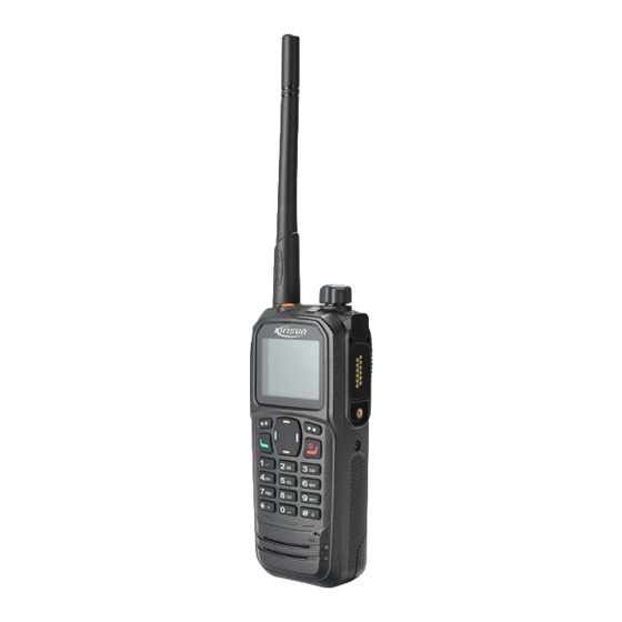
DP770 Service Manual 2. External View and Functional Keys 2.1. External View and Functional Keys Part Name Part Name Volume/Channel Knob Rotate the knob to adjust the volume.Short press the key, the Antenna feature of the knob switches from adjusting the volume to changing the channel. -
Page 6: Led Indicator
DP770 Service Manual Programmable, default: none. Press the key to select the items shown at the bottom left of the screen. Dial Key Press the key to send data or text 4-way Navigation Key messages. Right Key ON/OFF/Hookoff Key Press the key to select the items Return to the standby screen. -
Page 7: Circuit Description
DP770 Service Manual 3. Circuit Description 3.1. RF Section Figure 3-1 RF Schematic Diagram 3.1.1. Transmitter Circuit Figure 3-2 Transmitter Circuit Diagram Antenna Microstrip Attenuator Matcher Pre-Driver1 Pre-Driver2 Drive-stage Final-stage Tx/Rx Switch Low-pass Filter Gate voltage control Subtracter To RX... - Page 8 DP770 Service Manual The transmitter circuit includes three parts: • Transmitter Power Amplifier The carrier signal generated by the TX VCO is modulated and amplified, and feeds to the transmitter circuit via the following steps. Step1: The signal passes a Π-type attenuator, realizing segregative isolation between RF power amplifier circuit and TX VCO.
-
Page 9: Receiver Circuit
DP770 Service Manual 3.1.2. Receiver Circuit Figure 3-3 Receiver Circuit Diagram Antenna -120dBm -121dBm -109dBm -124dBm -106dBm Point A Low noise amplifier Band- pass filter Band-pass filter Low-pass filter Gain = 18dB Insertion loss = -3dB Insertion loss = -3dB... -
Page 10: Frequency Generation Unit
DP770 Service Manual The first IF signal (73.35MHz) output by the IF amplifier goes into AD9864 (UHF: U201, VHF: U91) via Pin 47 and completes the second mixer, where the signal is converted to the second IF signal (2.25 MHz). The second IF signal is converted to digital signal via ADC sampling, and output via the SSI interface. -
Page 11: Gps Circuit
DP770 Service Manual The frequency generation circuit is composed of VCO and PLL. It is the core module of the whole TX-RX system. This circuit provides accurate carrier frequency during transmission; and provides stable local oscillator signal during reception. It has a direct influence on the performance of the system. -
Page 12: Baseband Section
DP770 Service Manual Step1: The 1575.42MHz GPS signal is received by the antenna, and then goes to HPF to remove the in-band signals used for transmission and reception. Step2: The signal goes to GPS module for amplification and filtering after frequency selection via filter. - Page 13 DP770 Service Manual process audio signal and digital signal. The audio amplifier TDA8547TS is used to amplify the analog audio signal. DSP processes digital signal (i.e audio signal encoding/decoding, digital I/Q signal decoding, digital audio signal processing). The AD9864 converts and processes the RF IF, and sends un-demodulated serial digital signal to the DSP for processing.
-
Page 14: Function Instruction And Parameters Setting
DP770 Service Manual Figure 3-9 The Composing of System Basic Peripheral Temperature CVDECT Voltage detect INT_MIC EXT_MIC OmapL138 TF card Voice level detect IIC0 UART0 Key scan module Accelerometer IIC1 Codec controler 4. Function Instruction and Parameters Setting 4.1. General Functions •... -
Page 15: Parameters Setting
• Parameters setting steps as follow: Step 1. Install the right version of Kirisun CPSp. Step 2. Connect radio with computer by Kirisun programming cable. Step 3. Make sure radio’s power is on. Step 4. Execute CPSp and start operation. - Page 16 DP770 Service Manual Step 4. Click “Next” to enter into installation information confirmation interface. Figure 4-3 Step 5. Click “Next” to enter into the finished interface. Figure 4-4 Page 15 of 102...
- Page 17 DP770 Service Manual Step 6. Click “Finish” to finish installation. Figure 4-5 Step 7. After successful installation, double click the software, as shown in Figure 4-6 Figure 4-6 Page 16 of 102...
-
Page 18: Assembly And Disassembly
DP770 Service Manual Users can read the radio’s date, or revise the data and then write into the radio. Please refer to the help file in the CPSp for the detailed operation instruction about Kirisun CPSp. Notes: Errors of parameter configuration may make certain functions cannot be used properly, in general, which can be solved by writing the correct parameters configuration. -
Page 19: Attaching And Detaching The Antenna
DP770 Service Manual Detaching the battery as shown in Figure 5-2 Push up the battery buckle at the end of the battery. Pull down to detach the battery. Figure 5-2 5.2. Attaching and Detaching the Antenna As shown in Figure 5-3, put the antenna into radio’s thread hole, and rotate clockwise to fasten it. -
Page 20: Attaching And Detaching The Belt Clip
DP770 Service Manual 5.3. Attaching and Detaching the Belt Clip As shown in Figure 5-5, align the screw holes on the belt clip, which is located on the back of the radio, and fasten them with the screwdriver. Figure 5-5 As shown in Figure 5-6, unfasten the screws to detach the belt clip. -
Page 21: Removing The Pcb Board From The Chassis
DP770 Service Manual Step 5. Refer to Figure 5-8. Insert the flat-bladed screwdriver into the slot of Al alloy bracket; lift it so as to separate the Zinc alloy bracket from the chassis, and then push the Al alloy bracket away from the chassis, and take the soft flat cable away from the socket. - Page 22 DP770 Service Manual Step 3. Remove the four screws from keypad board and take off keypad PCB from case. (See Figure 5-11) Figure 5-11 Step 4. After the detaching above, you can make the appropriate repairs and debug against fault conditions.
-
Page 23: Exploded View
Part Number Name, Specification Quantity 7WFP-4002-01A DP770lens protective film PET; transparent 7MHP-4002-02A-WC DP770 LCD lens PC+PMMA, transparent 7GCJ-S4002-J DP770 lens double sides adhesive tapeNITTO 57120B 7MHP-4002-04A-W9 DP770 PTT cover PC+ABS/TPU;black/PT2757C 7MHR-4002-10A-W6 DP770 Side silicone buttons silica gel; blue,PT654C 7SAF-020070M-SZYB-Z 2.0X7.0 iron... - Page 24 4PC7-4002H-A LCD display ZYW-T18CP-20PJ-B 7MHS-4002-03A-W Numeric key METAL DOME diameter 4.0;SUS301 6PM7-4002-HKG DP770KEY-LCD PCB Four-layer board 7SMF-020040M-SZYB-N M2*4 iron hardened tooth machine cross screw, Nylok DP770 main board double-sided adhesive foam black foam 7GCM-180090015-J 18*9*1.5 Socket black foam double-sided adhesive 7GCM-100090015-J foam10*9*1.5...
- Page 25 DP770 Service Manual 7SMF-020050M-MHHT- M2*5 plum blossom iron hardened tooth machine screw, nickel plating 6PD7-4002-HPC DP770PTT board PCB double side board 7MHS-4002-04A-W DP770 PTT key METAL DOME4.0; SUS301 7MHS-4002-05A-W DP770 ,0.6mm Platooninsert tabletting stainless steel 7MDZ-1737-04A-J5 KB-58L sticker 1 ,8*35*0.2...
-
Page 26: Tune Mode
DP770 Service Manual 6. Tune Mode It may need to check and adjust the parameters after parts replacement in maintenance. 6.1. Required parts in adjustment (1)Antenna adapter (2)Universal interface 6.2. Adjusting and checking method 6.2.1. Frequency description Model 400~470MHz Mid-frequen... -
Page 27: Adjustment Equipments
DP770 Service Manual 6.2.2. Adjustment Equipments (1)Comprehensive test instrument(HP8921 or similar equipment) (2)Computer and CPSp software (3)AEROFLEX 3920 (4)spectrum analyzer 6.2.3. Adjustment instruction of TX Test Tool and Method Remark Item Configuration Test Test Point Tool Method equipment 1)Enter tune mode;... - Page 28 DP770 Service Manual Connect the 1) Enter tune mode; Set the test instrument to tx antenna port to 2) Double click "Maximum Deviation". mode. HP8921A or RF IN/OUT port Maximum 3)Adjust the value in tune mode and view Set HF(High filter) to 50Hz...
-
Page 29: Receiver Section Adjustment Instruction
DP770 Service Manual 1)Enter tune mode 2)Double click”VOX10”. Set comprehensive Connect mic HP8921A or 3 ) Click “Start”, the radio will enter vox instrument to tx mode 1) port of the radio VOX 10 similar AFGen1 Freq:1kHz; to audio out of adjustment automatically. - Page 30 DP770 Service Manual 1)Set comprehensive instrument to RX mode 2)Set RF Gen Freq to test 1. Enter tune mode frequency 2. Double click”SQL1 Open”and enter to F1 3) Set Amplitude to to F8 to adjust different frequency SQL1 Open -123dBm1(25KHz) or -121dBm 3.
-
Page 31: Gps Performance Test Instruction
DP770 Service Manual Connect the antenna port to 1.Enter tune mode 1)Set comprehensive HP8921A or RF IN/OUT port 2.Double click ”RSSI1” The RSSI is instrument to RX mode RSSI 1 similar of instrument by 3. Click “Start”. displayed one 2) Set RF Gen freq to 400MHz... -
Page 32: Main Specifications
DP770 Service Manual 7. Main Specifications General Specifications UHF1: 400-470MHz, VHF: 136-174MHz Frequency 1024 Channel Capacity 12.5kHz/20kHz/25kHz Channel Spacing Weight 362g(with battery and antenna) 138mm*62mm*38mm Dimension 1.8 Inches 65535 Color Display Display Battery Capacity 7.4V 2000mAH Li-ion Analog: 13.5 Hours Working Time(5-5-90)... - Page 33 DP770 Service Manual Digital Sensitivity 0.3uV(5% BER) Intermodulation ETSI: 65dB TIA603: 70dB Adjacent Channel Selectivity ETSI/TIA603: 60dB@12.5kHz,70dB@20/25kHz Spurious Response Rejection ETSI/TIA603: 70dB Conducted Spurious Emission -57dBm Block ETSI: 84dB TIA603: 80dB Rated Audio Power 0.5W <3% (Typical) Rated Audio Distortion Hum and Noise -40dB@12.5kHz/-43dB@20kHz/-45dB@25kHz...
-
Page 34: Repairing And Testing Equipments
DP770 Service Manual 3% (Typical) Audio Distortion Vocoder AMBE++ Digital Data Protocol ETSI TS 102 361-1, -2, -3 <1min TTFF(cold start) Time to first fix <10s TTFF(Hot start)Time to first fix <10meters Horizontal Accuracy 8. Repairing and Testing Equipments Installations... -
Page 35: Basic Troubleshooting
DP770 Service Manual Frequency: 50Hz-10KHz Audio Frequency Voltmeter Voltage: 1mv-10v Frequency: 50Hz - 5KHz or higher Tone Generator Output: 0-1v Power: when 1KHz, ≤3% Distortion Meter Input PWL: 50mv-10vms Spectrum analyzer Range:100-3GHz or higher 16Ω Dummy Load 16Ω, 3W Output Voltage 5v- 30v, current:5A Power Supply 9. - Page 36 DP770 Service Manual A. Check whether the antenna is GPS+UHF dual band or not. If not, use a GPS+UHF dual band antenna to replace the old one. GPS cannot locate your position. B. Check whether the GPS setting is correct or not. If not, set it correctly.
-
Page 37: Appendix 1 Material List(Electrics Parts)400-470Mhz
DP770 Service Manual Appendix 1 Material List(Electrics Parts)400-470MHz Part Number Name Quantity Position Mark 6SS2-4002B-HMD DP770 Main Board suite(BD+GPS) 1 DP770-02 main board SMD suite 6SS1-4002B-HMC (BD+GPS) DP770-02 main board 0SS1-4002B-HME units(BD+GPS) 1DR1-1SR154-400 R SMD commutation diode D903 1DS1-DA2S10100L R SMD switch diode D110,D111,D113,D701,D702,D703,D704,D15,D506... - Page 38 R SMD Specialized IC U703 1IS1-TLV320AIC14K CODEC IC U801 1IS1-TLV5614 DA convertor IC U105 1IS1-TPS62110 Power Chip U901 Power management Chip DP770, 1IS1-TPS65023 U902 DP780,KH620D,STR,STP 1IS1-XC6204B302M SMD voltage regulated U112 1IS1-XC6204B502M R SMD voltage regulated U101,U202 1TC1-UMC4 R SMD multiunit tube U107,U108,U109,U301...
- Page 39 DP770 Service Manual 1TF1-RD07MUS2B E R SMD FET Q304 1TF1-ST2301 R SMD FET Q905,Q907,Q908,Q901 1TT1-2SC3356-R24 R SMD triode Q103,Q104,Q302,Q305 1TT1-2SC4617-R R SMD triode Q102,Q105,Q107 1TT1-2SC5006 SMD triode Q201,Q203,Q204,Q206,Q207,Q301 1TT1-AT41511 Low Noise NPN triode Q205 1TT1-DTC144EE R SMD triode Q903,Q1,Q801,Q805,Q30,Q202,Q306,Q309 1TT1-FMMT717TA...
- Page 40 DP770 Service Manual 2CC1-10-C0G500-1R R flake multi-layer capacitor C117,C149 2CC1-10-C0G500-20 R flake multi-layer capacitor C320 2CC1-10-C0G500-22 R flake multi-layer capacitor C124,C268 2CC1-10-C0G500-27 R flake multi-layer capacitor C213,C214 2CC1-10-C0G500-27 flake multi-layer capacitor C842,C358,C359,C613,C810,C811,C818,C819,C828 2CC1-10-C0G500-2R flake multi-layer capacitor C266 2CC1-10-C0G500-30 flake multi-layer capacitor C248 C1027,C1028,C1029,C1030,C1031,C1032,C1033,C1034,...
- Page 41 DP770 Service Manual 2CC1-10-C0G500-56 R flake multi-layer capacitor C317,C328 2CC1-10-C0G500-5R flake multi-layer capacitor C250,C283 2CC1-10-C0G500-6R R flake multi-layer capacitor C129,C130,C264 2CC1-10-C0G500-7R flake multi-layer capacitor C253,C277 2CC1-10-C0G500-8R flake multi-layer capacitor C274 2CC1-10-C0G500-9R flake multi-layer capacitor C307 2CC1-10-X5R100-10 flake multi-layer capacitor C36,C38,C411,C412,C703,C710,C1136,C612,C812,C814...
- Page 42 DP770 Service Manual 2CC1-10-X7R250-22 R flake multi-layer capacitor C706,C711 C153,C212,C5,C6,C25,C927,C930,C933,C936,C939,C942,C957, 2CC1-10-X7R500-10 R flake multi-layer capacitor C960,C967,C976,C979,C984,C985,C998,C1003,C1018,C1021,C 1025,C1026,C916 C122,C125,C171,C173,C206,C207,C208,C209, 2CC1-10-X7R500-10 C210,C211,C219,C220,C226,C228,C234,C237,C239,C243,C247 R flake multi-layer capacitor ,C249,C256,C272,C275,C276,C278,C280,C287,C288,C306,C31 6,C322,C353,C355,C802,C807,C823,C831,C824 2CC1-10-X7R500-27 R flake multi-layer capacitor C342 2CC1-10-X7R500-33 R flake multi-layer capacitor C152 2CC1-16-C0G500-10 R flake multi-layer capacitor...
- Page 43 DP770 Service Manual 2CC1-16-C0G500-27 R flake multi-layer capacitor L304 2CC1-16-C0G500-2R flake multi-layer capacitor C332,C337 2CC1-16-C0G500-3R flake multi-layer capacitor C169 2CC1-16-C0G500-3R R flake multi-layer capacitor C333 2CC1-16-C0G500-43 R flake multi-layer capacitor C325 2CC1-16-C0G500-47 R flake multi-layer capacitor C176 2CC1-16-C0G500-4R flake multi-layer capacitor...
- Page 44 DP770 Service Manual 2CC1-16-C0G500-6R R flake multi-layer capacitor C161,C144 2CC1-16-C0G500-R5 R flake multi-layer capacitor C336 2CC1-16-X7R6R3-10 SMD ceramic capacitor C702,C804,C805,C821,C826,C809,C37 2CC1-16-Y5V100-22 flake multi-layer capacitor C921 2CC1-16-Y5V160-10 R flake multi-layer capacitor C323,C801,C806,C820,C907,C919 2CC1-20-Y5V160-10 flake multi-layer capacitor C915,C917,C923 2CC1-32-X5R100-47 SMD flake multi-layer capacitor C101,C102,C105,C106,C241,C242,C352,C902,C904,C2...
- Page 45 DP770 Service Manual 2CT1-TS32-350-R10 R SMD tantalum capacitor C126 2CT1-TS32-350-R33 R SMD tantalum capacitor C128 2LH1-R401R5-R02-0 SMD air-core inductance L310 2LH1-R401R5-R03-0 R SMD air-core inductance L311,L312 2LH1-R401R5-R04-0 R SMD air-core inductance L207,L208,L211,L212,L313,L314 2LH1-R401R5-R08-0 R SMD air-core inductance L309 2LH1-R501R5-R05-0 SMD air-core inductance...
- Page 46 DP770 Service Manual 2LW1-16UC-R33G SMD coil inductance L104,L105,L107,L110,L111,L114,L217 2LW1-20UC-120GA SMD coil inductance L103 2LW1-20UC-221J R SMD coil inductance L316 2LW1-20UC-331J SMD coil inductance L201 2LW1-20UC-8R2J SMD coil inductance L113 2LW1-25UC-103J R SMD coil inductance L202,L203 2LW1-25UC-332K SMD coil inductance L205 R31,R32,R830,R822,R706,...
- Page 47 DP770 Service Manual 2RS1-10-124J R flake resistor R167,R236 2RE1-10-2200 SMD precision resistor R305,R307 2RS1-10-151J R flake resistor R233 2RS1-10-152J R flake resistor R323 2RS1-10-153J R flake resistor R713,R716 2RS1-10-154J R flake resistor R104,R906 2RS1-10-182J R flake resistor R132 2RS1-10-183J R flake resistor...
- Page 48 DP770 Service Manual 2RS1-10-363J R flake resistor R335 2RS1-10-392J R flake resistor R108,R226,R227 2RS1-10-470J R flake resistor R113,R215,R219 2RS1-10-471J R flake resistor R340,R611 2RS1-10-472J R flake resistor R4,R143,R234,R703,R704,R801,R807,R913,R914,R12,R15,R36 R137,R322,R171,R172,R173, 2RS1-10-473J R flake resistor R174,R279,R280,R283,R284,R287,R288,R297,R298,R908 2RS1-10-510J flake resistor R191,R230,R308,R329 2RS1-10-511J R flake resistor...
- Page 49 DP770 Service Manual 2RS1-10-562J R flake resistor R107,R235 2RS1-10-680J R flake resistor R109,R809 2RS1-10-682J R flake resistor R310,R338 2RS1-10-684J R flake resistor R214 2RS1-10-6R8J flake resistor R110,R111,R112,R145 2RS1-10-753J R flake resistor R220 2RS1-10-822J R flake resistor R126,R131,R231 2RS1-10-823J R flake resistor...
- Page 50 DP770 Service Manual 2RS1-20-000O R flake resistor FB901 2RS1-32-R39J R flake resistor R319,R320,R337 RN1,RN2,RN3,RN4,RN5,RN6,RN8,RN9,RN10, 2RS2-20-101J08B SMD Network resistor RN11,RN14,RN15,RN16,RN17,RN18,RN19,RN20,RN21, RN22,RN24,RN25,RN26,RN27,RN28,RN29 2RT1-NTH5G16P40B SMD thermistor R326 333J board-to-board connector 3CB1-DF23C-50DS J902 DP770 DP780 3CM1-TFC-008-J Flat TF clutch base 3CP1-TPS76301 LDO power regulator...
- Page 51 C1132,C1143 1DR1-BAT54C SMD schottky diode 1TF1-BSH203 SMD FET GPS/BEIDOU dual module (DP770 1MR1-MC-1010B 780 DM880) GPS front end module pack DP770 1IS1-SKY65709-81 DP780 7MHC-4002-02A-W DP770 shield cover bracket1 7MHC-4002-04A-W DP770 shield cover bracket2 7MHC-4002-16A-W1 GPS shield cover base...
- Page 52 High Temperature Sticker 1IP1-0DP770-R01 DP770 burning chip U904 1IM1-NANDS34ML01 SMD Memorizer IC U904 9FSO-DP770V081 DP770-02 Firmware Software 6SS2-4002-HKC DP770 keypad SMD suite 0SS2-4002-HKA DP770 keypad plug-in units 6SS1-4002-HKG DP770 keypad SMD suite) 0SS1-4002-HKG DP770 keypad plug-in units 2CC1-10-X5R100-10 flake multi-layer capacitor C1,C24,C25,C26,C411,C413,C416,C417,C419,C423,C424...
- Page 53 I2C control keypad scan IC U926 6PM7-4002-HKG DP770KEY-LCD PCB board 3FW1-0603L025 Fuse F901 2CC1-10-X5R6R3-22 R flake multi-layer capacitor C439 ,C440,C441,C438 2RS1-10-4R7J R flake resistor 6SS1-4002-HL1G DP770 main ribbon cable SMD suite DP770 main ribbon cable SMD 0SS1-4002-HL1G unites Page 52 of 102...
- Page 54 DP770 Service Manual 3CB1-DF23C-50DS SMD board-to-board connector 6PD7-4002-HL1H DP770 main ribbon cable 3CB1-DF23C-50DP SMD board-to-board connector DP770 channel knob connecting wire 6SS2-4002-HL2D suite DP770 channel knob connecting wire 0SS2-4002-HL2B plug in units 3SE3-RE11 Channel Knob(DP770,AP670 J4001 DP770 channel knob connecting wire...
-
Page 55: Appendix 2 Material List(Electrics Parts)136-174Mhz
DP770 Service Manual Appendix 2 Material List(Electrics Parts)136-174MHz Part No. Part Name Quantity Location SMD button battery 6BLS-4814-03327U (DP770, DM890, BT10 PT7800, 219, 620D) 2CC1-32-X5R6R3-10 SMD flake multi-layer C1,C179,C227 capacitor C2,C6,C9,C11,C15,C19,C26,C50,C53,C62,C65,C74,C77,C100,C103,C107,C110,C1 2CC1-10-X5R100-10 flake multi-layer 13,C116,C120,C125,C126,C127,C132,C134,C138,C140,C142,C146,C148,C150,C15 capacitor 5,C164,C180,C183,C184,C456 2CC1-10-C0G500-9R flake multi-layer... - Page 56 DP770 Service Manual 10,C211,C212,C437,C245,C284,C334,C335,C341,C342,C343,C344,C345,C349,C35 0,C362,C86,C403 2CT1-TP20-100-100 R SMD tantalum C18,C25,C32,C34,C236 capacitor 2CC1-32-X5R100-47 SMD flake multi-layer capacitor 2CC1-10-X7R500-10 R flake multi-layer C24,C90,C92,C163,C176,C440,C47,C94,C97,C122,C250,C299,C326,C369,C374,C4 capacitor 32,C436,C458,C462,C466,C187,C377,C380,C384,C434,C48,C457,C460,C454,C465 2CC1-10-X5R6R3-22 R flake multi-layer capacitor C36,C376,C455,C461,C188,C220,C222,C237,C270,C314,C316,C317,C318,C319,C3 2CC1-10-X7R500-10 R flake multi-layer 20,C323,C325,C329,C339,C340,C352,C354,C360,C361,C365,C373,C404,C405,C40 capacitor 6,C408,C409,C430,C433,C453,C463,C493,C278 2CC1-10-C0G500-11 R flake multi-layer...
- Page 57 DP770 Service Manual 2CC1-10-X7R160-33 R flake multi-layer C151,C152 capacitor 2CC1-10-C0G500-27 flake multi-layer C157,C158,C159,C160,C439,C263,C451,C452 capacitor 2CC1-10-X7R250-22 R flake multi-layer C162 capacitor 2CT1-TS32-250-2R2 SMD tantalum capacitor C171,C272 2CC1-10-C0G500-33 R flake multi-layer C172,C173,C174,C175,C367,C324 capacitor 2CC1-10-C0G500-3R flake multi-layer C275 capacitor 2CC1-10-C0G500-13 R flake multi-layer...
- Page 58 DP770 Service Manual capacitor 2CC1-16-C0G500-10 R flake multi-layer C243,C282 capacitor 2CC1-10-C0G500-8R flake multi-layer C393 capacitor 2CT1-TS32-350-R10 R SMD tantalum C271 capacitor 2CT1-TS32-350-R33 R SMD tantalum C273 capacitor 2CC1-16-C0G500-10 R flake multi-layer C274,C477,C480,C482,C486 capacitor 2CC1-10-C0G500-6R R flake multi-layer capacitor 2CC1-16-C0G500-24 R flake multi-layer...
- Page 59 DP770 Service Manual 2CC1-10-C0G500-18 R flake multi-layer C381,C383,C441,C87,C442 capacitor 2LL1-16-R10JB Laminated indcutor L63,L5 2CC1-10-X7R160-47 R flake multi-layer C448 capacitor 2CC1-16-C0G500-47 R flake multi-layer C449 capacitor 2CC1-10-X7R250-12 R flake multi-layer C450 capacitor 2CC1-16-Y5V160-105 R flake multi-layer C464 capacitor 2CC1-16-C0G500-12 R flake multi-layer...
- Page 60 DP770 Service Manual diode DP770,DP780, STP,KH620 SMD voltage regulated 1DZ1-PESD12VS1UB diode R SMD commutation 1DR1-1SR154-400 diode 1DS1-DAN222 R SMD switch diode 1DS1-DA2S10100L R SMD switch diode D10,D11,D12,D13,D21,D25,D31,D50,D36,D37 1DR1-BAT54C SMD Schottky diode; R SMD switch diode 1DS1-HSC277 (production halt) R SMD varactor 7200,...
- Page 61 DP770 Service Manual connector 3CM1-TFC-008-J Flap TF clutch base SMD board-to-board 3CB1-DF23C-50DS connector DP770 DP780 3CC1-USB-UH51543- USB port AB-type socket 2LL1-30-VLS3012T10 Laminated inductance L1,L2,L3,L4 2LW1-16UC-R33G SMD coil inductance L20,L21,L25,L28,L29,L33,L69,L67 2RS1-16-000O R flake resistor L65,L66,R268 2LW1-16UC-390G SMD coil inductance L9,L52 2LL1-16-3N9S...
- Page 62 DP770 Service Manual inductance 2LW1-20UC-102J SMD coil inductance 2LH1-R401R2-L03-05 SMD air-core inductance R SMD air-core 2LH1-R301R0-L04-05 inductance R SMD air-core 2LH1-R301R2-L05-05 inductance R SMD air-core 2LH1-R301R0-L07-05 inductance 2LH1-R401R5-L07-05 R SMD air-core loop R SMD air-core 2LH1-R301R0-L08-05 inductance 2RS1-20-103J Flake resistor...
- Page 63 DP770 Service Manual series/6500/7200/567/D P770/780/STP/560/AP57 E R SMD FET portable 1TF1-RD01MUS2 digital and analogue material R1,R51,R53,R116,R120,R141,R142,R216,R250,R285,R286,R287,R294,R296,R303, 2RS1-10-101J R flake resistor R309,R340,R350,R83,R84,R361 2RS1-10-474J R flake resistor R2,R177 2RS1-10-202J R flake resistor R3,R262,R334 2RS1-10-514J flake resistor C346,R5,R36,R37,R38,R49,R50,R73,R220,R222,R17,R20,R21,R22,R25,R26,R27,R 28,R29,R30,R31,R32,R35,R74,R75,R78,R91,R92,R94,R95,R96,R98,R101,R156,R15 2RS1-10-103J R flake resistor...
- Page 64 DP770 Service Manual 2RE1-10-1501 SMD precision resistor R66,R82,R406 2RE1-10-1002 SMD precision resistor R69,R310,R311 2RE1-10-49R9-D SMD precision resistor 2RS1-10-301J R flake resistor R358,R359 2RS1-10-180J R flake resistor R356 2RS1-10-243J R flake resistor R88,R325 2RS1-10-561J R flake resistor R89,R369 2RS1-16-103J R flake resistor...
- Page 65 DP770 Service Manual 2RE1-10-3302 SMD precision resistor R428 2RS1-10-822J R flake resistor R319,R375,R364 2RS1-10-511J R flake resistor R332 2RS1-10-203J R flake resistor R335,R379 2RS1-10-124J R flake resistor R353,R376 2RS1-10-184J R flake resistor R360 2RE1-10-2203 SMD precision resistor R363,R365,R367,R368,R396,R402,R409,R412 2RS1-10-683J R flake resistor...
- Page 66 DP770 Service Manual 5XC1-19R2-TKL3056 SMD crystal oscillator DP770 STP KH620 1IP1-OMAPL138BZW Dual core CPU 1IM1-MT47H64M16 SMD memorizer IC 1IS1-TC75W51FU R SMD specialized IC 1IS1-TLV320AIC14K CODEC chip 1IL1-TDA8547TS E general linear IC SMD general logic IC 1ID1-MXD2020ML (accelerated sensor) SMD voltage regulated...
-
Page 67: Appendix 3 Material List (Structural Section)
7GCJ-S4002-J DP770lens double-sided tape NITTO 57120B 7MHP-4002-04A-W9 DP770 PTT cover plate PC+ABS/TPU; black/PT2757C 7MHR-4002-10A-W6 DP770 side silica gel key silica gel; blue,PT654C; 7SAF-020070M-SZYB-Z1 2.0X7.0 cross machine screw with iron hardened; black-zinc-plated 7MHP-4002-01A-W0 DP770 main unit front shell PC+ABS, black 6SS1-4002-HL3C... - Page 68 7MHR-4002-15A-W9 DP770 antenna water-proof gasket silica gel; black φ8 DC vibrating motor KFF081522, 4MV3-KFF081522 7MHR-4002-17A-W9 DP770 silica gel of motor silica gel gasket; black; 7MHS-4002-02A-W DP770 motor presser stainless steel; original color; pb-free 6BPM-933948-074200-B li-polymer battery7.4V,2100mAh Page 67 of 102...
- Page 69 DP770 battery bottom cover PC+ABS; black 7MHR-4002-18A-W9 DP770 discharging base silica gel; black 7MHP-4002-01A-W TD7700 battery connector BC-2P-41PH-6.8H 7MHC-4002-02A-W DP770 shielding cover bracket 1; 43.4*32.3mm; copper-nickel 7MBM-S4002-A Conductive foam 12*7*7; with double-sided adhesive 7MHC-4002-16A-W1 GPS shielding cover base 1; copper-nickel; pb-free 7MHC-4002-04A-W DP770 shielding cover bracket 2;...
-
Page 70: Appendix Figure 1 Dp770 Uhf Main Board Top Side Pcb View
DP770 Service Manual Appendix Figure 1 DP770 UHF Main Board Top Side PCB View Page 69 of 102... -
Page 71: Appendix Figure 2 Dp770 Uhf Main Board Bottom Side Pcb View
DP770 Service Manual Appendix Figure 2 DP770 UHF Main Board Bottom Side PCB View Page 70 of 102... -
Page 72: Appendix Figure 3 Dp770 Uhf Keypad Top Side Pcb View
DP770 Service Manual Appendix Figure 3 DP770 UHF Keypad Top Side PCB View Page 71 of 102... -
Page 73: Appendix Figure 4 Dp770 Uhf Keypad Bottom Side Pcb View
DP770 Service Manual Appendix Figure 4 DP770 UHF Keypad Bottom Side PCB View Page 72 of 102... -
Page 74: Appendix Figure 5 Dp770 Uhf Main Board Schematic Diagram
DP770 Service Manual Appendix Figure 5 DP770 UHF Main Board Schematic Diagram NAND512W3A2SZA6 RF PART MT47H64M16 McASP MOTO Digital Interface 2*MIC OMAP-L138 TLV320AIC14 TDA8547 CODEC AUDIO PA accelerometer 2*SPEAK AUIDIO&Channel SYS_RESET 1V2 1V8 3V3 TPS65023 BATTERY ZYW-T18CP-20PJ-B(1.77D) RF TEMP ADS1015... - Page 75 DP770 Service Manual POWER Q106 R142 FMMT717 C173 10nF C172 SYN_5V Q105 10uF/16V RF_5V5 U101 RF_5V5 Q102 D112 1IS1-XC6204B502MR 2SC4617 RXVCOCTR 2SC4617 C171 HSC277 10nF POWER FB101 U107 BLM18PG181SN1 R101 R106 UMC4 R143 D110 4.7k R162 MA2S111 C101 47uF/35V C107 0.1uF...
- Page 76 DP770 Service Manual U112 POWER SYN_3V_AD9864 1IS1-XC6204B302MR R165 FB201 R201 Q107 510R C105 R166 C106 2SC4617 47uF/35V SYN_5V 47uF/35V 5FE1-BLM11A0402S/1k R192 R105 D113 C217 MA2S111 AD9864_POWER R202 0.1uF C184 TP201 10uF/16V TEST_POINT C183 C211 10nF 10uF/16V C215 C216 R204 C207...
- Page 77 DP770 Service Manual FB202 5FE1-BLM11A601S/1k RX_5V U202 POWER RX_5V 1IS1-XC6204B502MR R215 R219 RXCTR R211 C243 C247 C242 10nF 10nF 47uF/35V C244 R220 L220 C249 33nH±2% 100pF R213 L206 10nF C241 R212 180k 27nH 47uF/35V L222 L221 27nH 27nH R217 C248...
- Page 78 DP770 Service Manual R340 Q306 Q307 470R DTC144EE FMMT717 R339 C353 10nF 100k DTC144EE TXCTR FB301 R341 5FE1-BLM11A601S/1k BAT_7V5 R304 R308 C355 L317 R348 TX_CONTROL 100R 10nF 22nH C344 U301 UMC4 U303-A R301 L302 C306 R309 L305 C346 R316 0.1uF...
- Page 79 DP770 Service Manual GPS_3V3_V GPS_3V3_V VBAT BAT_7V5 R361 VOUT GPS_3V3_V DC_1V2 MA2S111 MA2S111_NC 0R_NC 2SK1824 C411 R364 R360 TPS76301DBVR 200K XC6228D122VR 100K R362 0R_NC C412 100K BETTARY2_0 GPS_3V3 GPS_3V3_V GPS_3V3_V TP21 FB920 2.2K C1136 GPS_3V3 FB919 BLM21PG221SN1D C1135 0.1uF GPS_LDO_3V3...
- Page 80 DP770 Service Manual OMAP-L138ZWT U906-A RN19 100R*4 DDR_A[13] T5 SD_CLK MMCSD0_CLK/PRU1_R30[31]/GP4[7] MDDR_A12 SD_CMD EMA_A[22]/MMCSD0_CMD/PRU1_R30[30]/GP4[6] DDR_A[12] MDDR_A11 SD_D0 EMA_A[21]/MMCSD0_DAT[0]/PRU1_R30[29]/GP4 DDR_A[11] MDDR_A10 NAND_FLASH_3V3 SD_D1 RN20 100R*4 EMA_A[20]/MMCSD0_DAT[1]/PRU1_R30[28]/GP4 DDR_A[10] SD_D2 EMA_A[19]/MMCSD0_DAT[2]/PRU1_R30[27]/GP4 DDR_A[9] MDDR_A9 SD_D3 MDDR_A8 EMA_A[18]/MMCSD0_DAT[3]/PRU1_R30[26]/GP4 DDR_A[8] GPIO3 MDDR_A7 EMA_A[17]/MMCSD0_DAT[4]/PRU1_R30[25]/GP4 DDR_A[7] GPIO2 RN21...
- Page 81 DP770 Service Manual CPU_3V3 OMAP-L138ZWT U906-C R197 VP_DOUT[15]/LCD_D[15]/UPP_XD[7]/GP7[7]/B P4 VP_DIN[15]_VSYNC/UHPI_HD[7]/UPP_D[7]/PRU R198 VP_DIN[14]_HSYNC/UHPI_HD[6]/UPP_D[6]/PRU VP_DOUT[14]/LCD_D[14]/UPP_XD[6]/GP7[6]/B R199 VP_DIN[13]_FIELD/UHPI_HD[5]/UPP_D[5]/PRU VP_DOUT[13]/LCD_D[13]/UPP_XD[5]/GP7[5]/B R200 2.7K 0XX01110 0XX01110 NANDFL VP_DIN[12]/UHPI_HD[4]/UPP_D[4]/PRU0_R30[ VP_DOUT[12]/LCD_D[12]/UPP_XD[4]/GP7[4]/B R254 VP_DIN[11]/UHPI_HD[3]/UPP_D[3]/PRU0_R30[ VP_DOUT[11]/LCD_D[11]/UPP_XD[3]/GP7[3]/B 00011110 0001 1110 R255 VP_DIN[10]/UHPI_HD[2]/UPP_D[2]/PRU0_R30[ VP_DOUT[10]/LCD_D[10]/UPP_XD[2]/GP7[2]/B R256 VP_DIN[9]/UHPI_HD[1]/UPP_D[1]/PRU0_R30[9 VP_DOUT[9]/LCD_D[9]/UPP_XD[1]/GP7[1]/BOO R257 VP_DIN[8]/UHPI_HD[0]/UPP_D[0]/GP6[5]/PRU VP_DOUT[8]/LCD_D[8]/UPP_XD[0]/GP7[0]/BOO 100R*4 R297...
- Page 82 DP770 Service Manual J902 DF23C-50DS-0.5V INT-MIC+ EXT-MIC- INT-MIC- EXT-MIC+ EXT-SPK- IN-SPK- EXT-SPK+ IN-SPK+ C621 470pF R194 BLM18PG181SN1 PWR-SW+ IO_3V3 R193 BLM18PG181SN1 PWR-SW- IO_3V3 TCA8418_RESET CH_AC R637 UART_RXD BL_DIM CH_BC R636 USB_ID USB_VBUS I2C0_SCL USB+ I2C0_SDA USB- KEYBORAD_INT LCD_D0 LCD_CS LCD_D1...
- Page 83 DP770 Service Manual MARK MARK MARK MARK MARK MARK Hole Hole Hole Hole Hole Hole Hole Hole Hole Hole HOLE701 HOLE702 HOLE703 HOLE704 HOLE705 HOLE706 HOLE707 HOLE708 HOLE709 HOLE710 FB701 BLM18AG121SN1D LDO_3V3 R635 100K R634 Q908 ADC_EN ST2301 R723 0R NC...
- Page 84 DP770 Service Manual FB801 FB802 IO_3V3 LDO_3V3 BLM18AG121SN1D BLM18AG121SN1D C804 C807 C808 C801 C802 C803 C805 10uF 10nF 0.1uF C806 10nF 0.1uF 10uF R804 2.2k U801 C810 C811 TP801 TLV320AIC14 C809 270pF 270pF IO_3V3 10uF IOVSS AVSS IOVDD AVDD TP802...
- Page 85 DP770 Service Manual R932 R901 BLM21PG221SN1D-- BAT_7V5 100R POWER PWR-SW+ U901 BAT-PD700 FB901 R902 TPS62110 VCC_5V0 L901 Q901 F901 BLM21PG221SN1D-- ST2301 VIN1 R903 POWER_KEY_DET VIN2 10uH 2.5A-32V VCC_3V3 R928 J901 D902 100K + C2 R904 C905 C903 C904 VINA Q902...
-
Page 86: Appendix Figure 6 Dp770 Uhf Keypad Schematic Diagram
DP770 Service Manual Appendix Figure 6 DP770 UHF Keypad Schematic Diagram IO_3V3_0 IO_3V3_0 IO_3V3_0 UART_RXD/USB_ID OPTA_SEL02_1 EXT-SPK+ OPTA_SEL01_1 2RS1-10-102J 2RS1-10-102J OPTA_SEL00 R551R0 USB+ USB+ R552 R0 EXT-SPK- USB- EXT-MIC- USB_VBUS_0 LED8 LED7 5FE1-BLM15BB121SN1 EXT-MIC+ 4PE1-06-F5 4PE1-06-F2 CH_BC TOP_KEY CH_AC CH_AC... -
Page 87: Appendix Figure 7 Dp770 Vhf Main Board Top Side Pcb View
DP770 Service Manual Appendix Figure 7 DP770 VHF Main Board Top Side PCB View Page 86 of 102... -
Page 88: Appendix Figure 8 Dp770 Vhf Main Board Bottom Side Pcb View
DP770 Service Manual Appendix Figure 8 DP770 VHF Main Board Bottom Side PCB View Page 87 of 102... -
Page 89: Appendix Figure 9 Dp770 Vhf Keypad Top Side Pcb View
DP770 Service Manual Appendix Figure 9 DP770 VHF Keypad Top Side PCB View Page 88 of 102... -
Page 90: Appendix Figure 10 Dp770 Vhf Keypad Bottom Side Pcb View
DP770 Service Manual Appendix Figure 10 DP770 VHF Keypad Bottom Side PCB View Page 89 of 102... -
Page 91: Appendix Figure 11 Dp770 Vhf Main Board Schematic Diagram
DP770 Service Manual Appendix Figure 11 DP770 VHF Main Board Schematic Diagram 100R PWR-SW+ POWER BLM21P300S BAT_7V5 BB_7V5 VCC_5V BLM21P300S BB_7V5 3A/32V TPS62110 VCC_3V3 ST2301A VIN1 VIN2 POWER_KEY_DET 10uH BLM21P300S 470k C179 510k VINA 100nF 10pF PESD5V0S1UB 100nF 10pF 100uF/6.3V... - Page 92 DP770 Service Manual U30-A MMCSD0_CLK/PRU1_R30[31]/GP4[7] DDR_A[13] SD_CLK MDDR_A12 EMA_A[22]/MMCSD0_CMD/PRU1_R30[30]/GP4[6] DDR_A[12] SD_CMD MDDR_A11 EMA_A[21]/MMCSD0_DAT[0]/PRU1_R30[29]/GP4 DDR_A[11] SD_D0 MDDR_A10 EMA_A[20]/MMCSD0_DAT[1]/PRU1_R30[28]/GP4 DDR_A[10] SD_D1 MDDR_A9 EMA_A[19]/MMCSD0_DAT[2]/PRU1_R30[27]/GP4 DDR_A[9] SD_D2 MDDR_A8 EMA_A[18]/MMCSD0_DAT[3]/PRU1_R30[26]/GP4 DDR_A[8] SD_D3 MDDR_A7 EMA_A[17]/MMCSD0_DAT[4]/PRU1_R30[25]/GP4 DDR_A[7] MDDR_A6 EMA_A[16]/MMCSD0_DAT[5]/PRU1_R30[24]/GP4 DDR_A[6] MDDR_A5 OMAP_3V3 CODEC_RESET EMA_A[15]/MMCSD0_DAT[6]/PRU1_R30[23]/GP5 DDR_A[5] MDDR_A4 [10]...
- Page 93 DP770 Service Manual OMAP-L138ZWT U30-B FB10 OMAP_1V8 VCC_3V3 OMAP_3V3 OMAP_1V2 DVDD18_1 CVDD_1 BLM18PG181SN1 DVDD18_2 CVDD_2 DVDD18_3 CVDD_3 DVDD18_4 CVDD_4 DVDD18_5 CVDD_5 100pF 10pF 100nF 100pF 100nF 100pF 100nF 100pF 100nF 100pF DVDD18_6 CVDD_6 DVDD18_7 CVDD_7 DVDD18_8 CVDD_8 DVDD18_9 CVDD_9 DVDD18_10...
- Page 94 DP770 Service Manual OMAP_3V3 R139 680R R140 R141 100R R142 100R TONE OUTPA+ BL_PWM BL_DIM BLM18PG181SN1 R220 R222 C186 U910 QINGHUA 1000pF 1000pF 100nF 100nF 100nF RSTO R218 I2C1_SDA R219 I2C1_SCL OMAP_3V3 OMAP-L138ZWT 0XX01110 NANDFLASH(R97=10k) 00011110 DEBUG(R90=10k) U30-C VP_DIN[15]_VSYNC/UHPI_HD[7]/UPP_D[7]/PRU VP_DOUT[15]/LCD_D[15]/UPP_XD[7]/GP7[7]/B...
- Page 95 DP770 Service Manual NAND_FLASH_D0 I/Q0 MT47H64M16HR NAND_FLASH_D1 I/Q1 NAND_FLASH_D2 I/Q2 MDDR_1V8 NAND_FLASH_D3 I/Q3 MDDR_A12 NAND_FLASH_D4 I/Q4 MDDR_A11 NAND_FLASH_D5 I/Q5 C100 C101 C102 C103 C104 C105 MDDR_A10 NAND_FLASH_D6 I/Q6 MDDR_A9 NAND_FLASH_D7 I/Q7 100pF 10pF 100pF 10pF MDDR_A8 NAND_FLASH_A2 MDDR_A7 NAND_FLASH_A1 VDDQ...
- Page 96 DP770 Service Manual FB30 FB31 FB32 R170 VCC_3V3 LDO_3V3 VCC_1V8 AIC_D3V3 AIC_A3V3 AIC_1V8 BLM18PG181SN1 BLM18PG181SN1 BLM18PG181SN1 VOX_PWR C130 C131 C132 C133 C134 C135 C136 C137 C138 C139 C140 C141 C142 R171 OUT1 OUT2 10uF 100pF 100nF 100pF 100nF 100nF 100pF...
- Page 97 DP770 Service Manual GPS_3V3_V VBAT GPS_3V3_V BAT_7V5 R149 1k VOUT MA2S111 C126 C181 C180 R221 GPS_3V3_V DC_1V2 C125 R168 0R 10uF/6V3 XC6204B332MR R147 XC6228D122VR 100k R148 0R_NC C127 BT10 BAT_7V5 GPS_LDO_3V3 GPS_3V3 R130 GPS_3V3_V FB40 VOUT TP20 R223 IO_3V3 MANDOWN_PWR...
- Page 98 DP770 Service Manual OMAP_3V3 R240 R241 R242 FPC10 EXT-MIC- [6] INT-MIC+ EXT-MIC+ PTTB_C1 [6] INT-MIC- PTTB_C0 EXT-SPK- IN-SPK- C210 C211 C212 EXT-SPK+ IN-SPK+ 100pF 100pF 100pF C213 10pF [1] PWR-SW+ VCC_3V3 [1] PWR-SW- CH_AC TCA8418_RESET FB50 BLM18PG181SN1 PTT KEY BL_DIM...
- Page 99 DP770 Service Manual POWER UMC4 BLM21P300S RXVCOCTR [2,10] SYN_5V RF_5V5 POWER 2SC4617 C218 FB60 22uF/10V SYN_5V BLM18PG181SN1 R262 C224 FMMT717 MA2S111 0.1uF R260 C220 RF_5V5 XC6209B552MR 10nF C221 R266 10uF/16V 5.6k C228 C229 2SC4617 C223 C225 150pF 0.1uF 10uF/16V HSC277...
- Page 100 DP770 Service Manual POWER SYN_3V_AD9864 FB70 R332 C310 510R 2SC4617 SYN_5V 10uF/16V XC6204B302MR C311 10uF/16V BLM18PG181SN1 R334 AD9864_POWER [2] MA2S111 C312 0.1uF R335 C313 C314 TP50 10uF/16V 10nF C315 10uF/16V C321 C322 R336 R337 C316 C317 C318 C319 56pF C320...
- Page 101 DP770 Service Manual FB80 5FE1-BLM11A601S/1k RX_5V R350 R351 100R C360 C361 10nF 10nF C365 R354 R353 68nH 10nF 56nH 120k C122 C366 1000pF 39nH 33nH 10pF RX_5V POWER C367 R356 C369 33pF C368 [2] RXCTR 15pF C370 C371 C372 [9] RXLO1...
- Page 102 DP770 Service Manual R390 470R TX_CONTROL [4] FMMT717 DTC144EE FB90 C430 R391 5FE1-BLM11A601S/1k DTC144EE 10nF FB18 100k 5FE1-BLM11A601S/1k 560R TXVCOCTR [2,9] 560R_NC TXCTR R392 R235 UMC4 C434 BAT_7V5 C433 1000pF 1000pF 1000pF R393 10nF 100nH U110 U111-A C431 UMC4 C436 NJM2904 0.1uF...
-
Page 103: Appendix Figure 12 Dp770 Vhf Keypad Schematic Diagram
DP770 Service Manual Appendix Figure 12 DP770 VHF Keypad Schematic Diagram IO_3V3_0 IO_3V3_0 IO_3V3_0 UART_RXD/USB_ID OPTA_SEL02_1 EXT-SPK+ OPTA_SEL01_1 2RS1-10-102J 2RS1-10-102J OPTA_SEL00 R551R0 USB+ USB+ R552 R0 EXT-SPK- USB- LED8 EXT-MIC- USB_VBUS_0 LED7 5FE1-BLM15BB121SN1 EXT-MIC+ 4PE1-06-F2 4PE1-06-F5 CH_BC TOP_KEY CH_AC CH_AC...
Need help?
Do you have a question about the DP770 and is the answer not in the manual?
Questions and answers