Kirisun PT8000 Service Manual
Vhf/uhf mobile radio
Hide thumbs
Also See for PT8000:
- Service manual (32 pages) ,
- Instruction manual (11 pages) ,
- Instruction manual (11 pages)
Table of Contents
Advertisement
Quick Links
- 1 Chapter 2 Radio Overview
- 2 Chapter 3 Circuit Introduction
- 3 Chapter 4 Mode Introduction
- 4 Chapter 7 Main Technical Indexes
- 5 Chapter 8 Trouble Shooting Guide
- 6 Appendix 4 Accessories
- 7 Figure 1 Pt8000 Schematic Circuit Diagram
- 8 Figure 2 Pt8000 Main Board Schematic Circuit Diagram
- Download this manual
See also:
Instruction Manual
Advertisement
Table of Contents

Related Manuals for Kirisun PT8000


Summary of Contents for Kirisun PT8000
- Page 1 PT8000 SERVICE MANUAL VHF/UHF MOBILE RADIO V071215...
-
Page 2: Table Of Contents
20 dBm (100mW). Figure 2 PT8000 Main Board Schematic Circuit Diagram....22 Figure 3 PT8000 Top Main Board Position Mark Diagram....23 Do not turn on the power before the antenna or load Figure 4 PT8000 Bottom Main Board Position Mark Diagram..24 connection is completed. -
Page 3: Chapter 1 Introduction
Introduction the following table before using. Any articles are found lost or damaged, This manual applies to the service and maintenance of PT8000 series of please contact the distributor without delay. FM mobile radio, and is designed for the engineers and professional technicians that have been trained by our company. -
Page 4: Chapter 2 Radio Overview
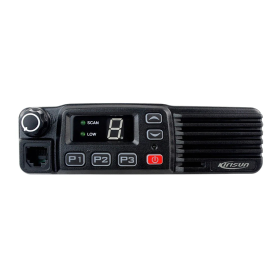
PT8000 SERVICE MANUAL Display Description At last, ring the remained conductor and fix it. SCAN indicator Scan indication: on when scan is enabled. Note: Please maintain the sufficient relaxation of the power cable to make it convenient to dismantle the radio in the state of power LOW indicator Power level indication: on when in low power. - Page 5 The first IF signal is filtered out adjacent channel and other useless signals by crystal filter (XF1). The PT8000 adopts PLL frequency synthesizer. The first IF signal from crystal filter is amplified by the first IF amplifier (Q20) Frequency synthesizer consists of reference oscillator, voltage controlled before processing of IC in IF( IC6 TA31136).
- Page 6 PT8000 SERVICE MANUAL Receiving Audio Signal Processing: CTCSS signals produced by MCU (PWM waveform) are sent to VCO for Audio sign als from IC6 are classified into two groups. One group is amplifi e d modulation after filtered the HF components over 300Hz in low pass filter and filtered in low pass circuit composed by IC8 (for audio signal ) , then the composed by RC.
- Page 7 PT8000 SERVICE MANUAL Port name Pin Name Function Port name Pin Name Function Connect Pull-down Resistor CPU Power 5V Input with VSS SHIFT Clock Beat Frequency Shift Connect Pull-down Resistor H On with VSS O(PWM) QT/DQT Output Frequency Voltage Regulation...
-
Page 8: Chapter 4 Mode Introduction
PT8000 SERVICE MANUAL Item Model Function Description Chapter 4 Mode Introduction Emergency Mode combinations Transmitting VCO Oscillation Circuit 2SK508NV Mode Function How to access Transmitting VCO Control Switch 2SC4116 User Mode For normal use Power on VCO Buffer Amplifier 2SC5108... -
Page 9: Chapter 5 Maintenance, Assembly And Disassembly
PT8000 SERVICE MANUAL . Pre-tips for TOT transmitting time limitation IF points of narrowband QT(254.1Hz) frequency offset Five frequency points of broadband DQT frequency offset . Re-key time of TOT transmitting overtime IF points of narrowband DQT frequency offset . Squelch level option Receiving five frequency points of sensitivity tuning voltage . - Page 10 PT8000 SERVICE MANUAL 1.Exploded view of the station Figure 5-1 ITEM PART NUMBER DESCRIPTION QTY. ITEM PART NUMBER DESCRIPTION QTY. 204-008000-R04 STRIP DUSTPROOF A 201-008000-R02 KNOB VOLUME CASE BOTTOM AL 203-008000-R01 203-006800-R26 SPRING PLATE 301-30250D-R01 SCREW M3*25 203-007200-R08 NUT VOLUME KNOB...
-
Page 11: Chapter 6 Overall Debugging
PT8000 SERVICE MANUAL 2.Instruction for disassembly of the station for maintenance 2 Instruction for disassembly of KEY-PCB 1 RF-PCB Disassembly Release the 6 screws (M3x25) for the upper and lower covers and open the aluminum alloy lower cover (see the figure below). - Page 12 PT8000 SERVICE MANUAL max point s respectively and set transmitting power to 5W by adjusting the Name Parameter requirements power attenuator number from 0 to 255. Decrement: 40db or 50db 6.2.5 Smooth regulation for DCS waveform (HP8920 is set to TX state...
- Page 13 PT8000 SERVICE MANUAL of adjusted frequency point, transmitting signal with amplitude of -122dBm, the five frequency points including min., low, intermediate, high and max audio frequency of 1kHz and frequency offset of 1.5kHz in antenna int- points. erface of vehicle station) and click Narrowband to adjust the five fre- 6.3.1 DTMF frequency offset (HP8920 is set to TX state and filter is at 50Hz...
-
Page 14: Chapter 7 Main Technical Indexes
PT8000 SERVICE MANUAL Table 6.5 Transmitting part Item Test condition Instrumentation correcting member requirement remarks Test point RF rate Frequency Counter / Integrated Tester Test mode Within 100Hz DCS waveform Oscillograph / Integrated Tester Nearly flat waveform (balance) Square wave... -
Page 15: Appendix 1 Abbreviations
PT8000 SERVICE MANUAL Appendix 1 Abbreviations amplify, amplifier micro control unit antenna microphone automatic power control modulation band pass filter MONI monitor CTCSS continuous tone control squelch system phase lock loop Digital code squelch push-to-talk DEMOD demodulation E2PROM E2PROM speaker... - Page 16 PT8000 SERVICE MANUAL 108-450C24-R02 450kHz Phase Frequency Detector / JTBM450CX24,ROHS 108-CF450F-R01 Plug-in porcelain filter / LTM450FW, 450kHz 7kHz,ROHS 108-CF450H-R01 Plug-in porcelain filter / LTM450HT, 450kHz 3kHz,ROHS 108-XF4995-R01 Plug-in IF filter / 49.95MHz 7.5KHz, Xf1, XF2 U-5*2,ROHS 109-040000-R01 Chip resistor / 0402,0R 5%,ROHS...
- Page 17 PT8000 SERVICE MANUAL 109-040913-R01 Chip resistor / 0402,91K 5%,ROHS R190 109-060000-R01 L52, L62 Chip resistor / 0603,0R 5%,ROHS 109-060100-R01 R29, R30 Chip resistor / 0603,10R 5%,ROHS 109-060102-R01 Chip resistor / 0603,1K 5%,ROHS R18, R19 109-060121-R01 Chip resistor / 0603,120R 5%,ROHS...
- Page 18 PT8000 SERVICE MANUAL 112-043471-R01 Chip capacitor / 0402,470P 10%,50V,X7R,ROHS C3, C9, C11, C12, C19, C20, C21, C38, C47, C49, C50, C51, C52, C54, C55, C57, C59, C68, C71, C87, C88, C89, C92, C95, C110, C116, C119, C123, C128, C136, C142, C143, C148,...
-
Page 19: Appendix 3 Framework Components List
PT8000 SERVICE MANUAL 114-06G471-R01 Chip inductor / MLF1608DR47K,470nH 10%,0603,ROHS 114-06G561-R01 Chip inductor / MLF1608DR56K,560nH 10%,0603,ROHS 114-06G820-R01 Chip inductor / MLG1608B82N,82nH 5%,0603,ROHS L34, L38 114-08E103-R01 Chip inductor / FSLM2520-100J,10uH 5%,1008,ROHS 114-08E331-R01 Chip inductor / FSLM2520-R33K,330nH 10%,1008,ROHS 114-08E821-R01 Chip inductor / FSLM2520-R82K,820nH 10%,1008,ROHS... -
Page 20: Appendix 4 Accessories
PT8000 SERVICE MANUAL Appendix 4 Appendix Name Type Specification Accessories Bracket Powercable Hand Microphone MIC KME215 Microphone Hanger Combination Screw M4.0*10.0 Self-tapping Screw M5.0*16.0 Self-tapping Screw M4.0*16.0... -
Page 21: Appendix 5 Pt8000 Spare Mechanical Part Bom
PT8000 SERVICE MANUAL Appendix 5 PT8000 SPARE MECHANICAL PART BOM ITEM PART NUMBER DESCRIPTION ITEM PART NUMBER DESCRIPTION 604-080000-R02 SUBASSEMBLY VOLUME KNOB 202-008200-R02A PLUG SPEAKER HOLE 203-007200-R08 NUT VOLUME KNOB 120-100000-R15 CABLE POWER 301-25050J-R01 SCREW M2.5*5 301-30100G-R01 SCREW M3*10 WITH SPRING PLATE... -
Page 22: Figure 1 Pt8000 Schematic Circuit Diagram
Figure 1 PT8000 Schematic Circuit Diagram 3.5V... -
Page 23: Figure 2 Pt8000 Main Board Schematic Circuit Diagram
Figure 2 PT8000 Main Board Schematic Circuit Diagram BLM11A601S... -
Page 26: Figure 5 Pt8000 Keyboard Schematic Diagram
Figure 5 PT8000 Keyboard Schematic Diagram... -
Page 27: Figure 6 Pt8000 Top Keyboard Position Mark Diagram
Figure 6 PT8000 Top Keyboard Position Mark Diagram... -
Page 28: Figure 7 Pt8000 Bottom Keyboard Position Mark Diagram
Figure 7 PT8000 Bottom Keyboard Position Mark Diagram...
Need help?
Do you have a question about the PT8000 and is the answer not in the manual?
Questions and answers