Kirisun PT8000 Service Manual
Professional two-way radio
Hide thumbs
Also See for PT8000:
- Service manual (28 pages) ,
- Instruction manual (11 pages) ,
- Instruction manual (11 pages)
Table of Contents
Advertisement
Quick Links
Advertisement
Table of Contents

Subscribe to Our Youtube Channel
Related Manuals for Kirisun PT8000


Summary of Contents for Kirisun PT8000
-
Page 2: Table Of Contents
Figure 2 PT8000 Main Board Schematic Circuit Diagram ...... 25 putting it in rain or snow, or any other liquid to ensure its life Figure 3 PT8000 Main Board Top Layer Position Mark Diagram ... 26 and performance. Figure 4 PT8000 Main Board Bottom Layer Position Mark Diagram ..27 Figure 5 PT8000 Keyboard Schematic Circuit Diagram...... -
Page 3: Chapter 1 Overview
After-sales service will be provided, and the length of contains all required service information for the equipment. warranty is stated by Kirisun. The radio and its accessories are all Kirisun reserves the right to modify the product structure and in the warranty. However, in one of the following cases, charge specifications without notice in order to enhance product free service will be not available. -
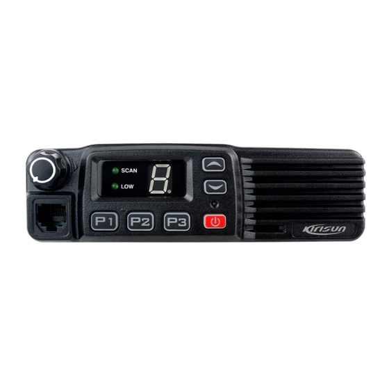
Page 4: Chapter 3 External View And Functional Keys
PT8000 Service Manual using the supplied mounting bracket so that the radio will not be 2.2 Licenses It is requested by rules that each radio installation site (for loosened in case of collision. mobile station or base station) should be provided with a license. -
Page 5: Chapter 4 Circuit Description
PT8000 Service Manual 5) Volume Knob Rotate to adjust the volume of the radio. 450KHz F 6) MIC Jack/Programming Interface 450KHz H 7) P1Button (Programmable Button) 49.95MHz AF AMP ANT SW RF AMP IF SYSTEM 8) P2 Button (Programmable Button) - Page 6 Figure 4.4 Frequency Synthesizer D20, D21, and the peripheral circuit. When the mobile radio is set PT8000 adopts PLL type frequency synthesizer. to wideband, CF2 is put through and takes effect, while CF1 is cut The frequency synthesizer consists of reference oscillator, off;...
- Page 7 PT8000 Service Manual 4.5 Audio Processing Circuit 4.6 Power Supply: The radio uses 13.8V battery, and the Tx power amplification circuit (IC1) and Rx audio power amplifier (IC7) directly adopt IC8A IC8D IC8C IC8B CTCSS/DCS the battery for power supply.
- Page 8 CTCSS frequency. In doing this, disturbance from other signals can be avoided. PT8000 has 39 groups of standard CTCSS frequencies for your selection. See Table 4.1. CTCSS signal (PWM wave) is generated by MCU, and is passed through low pass filter consists of RC to remove the high frequency components (above 300Hz).
- Page 9 PT8000 Service Manual 3SK318 Rx high power amplifier Power Detect Input 3SK318 First mixer RS-232C Output RS-232C Input 2SC5108 VCO buffer amplifier Reserved 2SC5108 IF amplifier Transmitting Power Control H: on 2SC4617 Rx noise amplifier Receiving Power Control H: on...
-
Page 10: Chapter 5 Mode Introduction
(3) Scan frequency, channels, CTCSS/DCS, scan, and other functional Scan Function on/off, Priority Channel, Revert Channel, Tx parameters should be reprogrammed. Therefore, Kirisun has Dwell Time, Dropout Delay Time, Lookback Time. specially designed a set of Chinese/English programming software (4) Emergency settings KSP8000 with friendly interface, convenient operation and visualized display for setting functional parameters of the radio. - Page 11 PT8000 Service Manual (2) Rx Signaling and Tx Signaling 9) Five frequency points for SQL1 Off (Wideband) a) None 10) Five frequency points for SQL1 On (Narrowband) b) CTCSS (60~260Hz @ 0.1Hz step) 11) Five frequency points for SQL1 Off (Narrowband)
-
Page 12: Chapter 6 Disassembly For Maintenance
PT8000 Service Manual 1. Press and hold P1 while turning the radio power ON to enter 203-007200-R08 Nut for Knob the Wired Clone Mode. The display will show “C”. If wired clone 204-006800-R01 LCD Protective Film function is disabled, the radio will enter User Mode. -
Page 13: Chapter 7 Adjustment
7.1 Equipment and Software Required for Test and Adjustment Equipment and software listed in Table 7.1 are required for test and adjustment of PT8000. Table 7.1 Equipment and Software Required for Test and Adjustment Figure 6.3... - Page 14 PT8000 Service Manual Input impedance: above 10MΩ/V DC, capable of DMM, the value should be larger than 0.6V. measuring voltage, current and resistance. Table 7.2 High/Center/Low Frequency Point for PT8000 Audio signal Frequency range:2-3000Hz generator Output level: 1-500mV Low Freq Point...
- Page 15 PT8000 Service Manual 7.2.7 QT (67.0) DEV (set the HP8920 to be in the Tx status, and to adjust the five frequency points of “Lowest”, “Low”, “Mid”, set the filter to be 20Hz ~ 300Hz) “High” and “Highest” respectively. a. In the “Tuning Mode”, double click “QT(67.0) DEV”, and b.
- Page 16 PT8000 Service Manual On”, and select “Narrowband”. Choose a frequency point, and Off”, and select “Narrowband”. Choose a frequency point, and click “Begin”, the programming software will adjust the value click “Begin”, the programming software will adjust the value automatically. When the value keeps stable, click “OK”, the automatically.
-
Page 17: Chapter 8 Specifications
PT8000 Service Manual mode on after SQL9 adjustment RF OUT: -114dBm SQL1 RF OUT: -121dBm Table 7.5 Transmitter Section Measurement Adjustment Item Test Condition Test Equipment Requirement Remark Terminal Parts Frequency counter Tx frequency Tuning mode Within ± 100Hz / General test set... -
Page 18: Appendix 1 Abbreviations
PT8000 Service Manual E. The CPU is broken, please change the IC. Appendix 1 Abbreviations A. Channel frequency goes beyond the limit, please unlocked reset the channel data. AMP: Amplify, Amplifier (Beeping) B. The PLL crystal oscillator X1 is broken. Please change... - Page 19 PT8000 Service Manual 103-1SV278-R01 Chip variable capacitor diode/ 1SV278,ROHS 103-A2S111-R01 Chip diode / 0603,MA2S111(PANASONIC),ROHS D12, D15, D22 103-AP1250-R01 Chip diode / MA4P1250-1072T,ROHS D3, D11 103-DAN222-R01 Chip diode / DAN222,(ROHM),ROHS D20, D21, D33 103-HSC277-R01 Chip diode/wave band switch, HSC277(HITACHI), ROHS D2, D19...
- Page 20 PT8000 Service Manual 109-040394-R01 Chip resistor / 0402,390K±5%, ROHS R202, R220 109-040433-R01 Chip resistor / 0402,43K±5%, ROHS R160, R163 109-040471-R01 Chip resistor / 0402,470R±5%, ROHS R100 109-040472-R01 Chip resistor / 0402,4.7K±5%ROHS R5, R16, R39, R76, R77, R91, R179, R187, R191, R195, R288, R289, R290 109-040473-R01 Chip resistor / 0402,47K±5%, ROHS...
- Page 21 PT8000 Service Manual 130 112-043221-R01 Chip capacitor / 0402,220P±5%,50V,C0G,ROHS C282 131 112-043222-R01 Chip capacitor / 0402,2200P±10%,50V,X7R,ROHS C248, C262 132 112-043223-R01 Chip capacitor / 0402,0.022uF±10%,50V,X7R,ROHS C158, C238, C239, C322 133 112-0432R0-R01 Chip capacitor / 0402,2P±0.25P,50V,C0G,ROHS C60, C161, C177 134 112-0432R5-R01 Chip capacitor / 0402,2.4P/2.5P±0.1P,50V,C0G,ROHS...
-
Page 22: Appendix 3 Structural Parts List
PT8000 Service Manual 187 114-06G120-R01 Chip inductor/ MLG1608B12NJT, 12nH±5%, 0603, ROHS L14, L15 188 114-06G180-R01 Chip inductor/ MLG1608B18NJT, 18nH±5%, 0603, ROHS 189 114-06G181-R01 Chip inductor / LGHK1608R18J-T, 180nH±5%, 0603, ROHS 190 114-06G220-R01 Chip inductor/ MLG1608B22NJT, 22nH±5%, 0603, ROHS L7, L8 191 114-06G221-R02 Chip inductor/ LGHK1608R22J-T, 220nH±5%, 0603, ROHS... - Page 23 PT8000 Service Manual 203-008200-R03A Antenna Connector 203-008200-R05A Shield for Power Module 204-006800-R01 LCD Protective Film 204-008000-R01A Dustproof Net for Speaker 204-008000-R02A Upper Dustproof Strip for Front Cabinet 204-008000-R03A Lower Dustproof Strip for Front Cabinet 204-008000-R04A Dustproof Strip between Top and Bottom Al Case...
- Page 24 PT8000 Al Top Case 204-008000-R03A PT8000 Lower Dustproof Strip for Front Cabinet 204-008000-R02A PT8000 Upper Dustproof Strip for Front Cabinet PT8000 Al Bottom Case Assembly (604-080000-R04) Part No. Name 203-008000-R01A PT8000 Al Bottom Case 204-008000-R04A PT8000 Dustproof Strip Between Top and Bottom Case...
-
Page 25: Appendix 4 Accessories
PT8000 Service Manual PT8000 Key-PCB Assembly Part No. Name Key-PCB 203-008000-R05A Metal Dome Appendix 4 Accessories Name Model Specifications External View Mounting bracket Power cable Hand microphone KME215 Microphone hanger KME209 SEMS M4.0*10.0 Self-tapping screw M5.0*16.0 Self-tapping screw M4.0*16.0... - Page 26 PT8000 Service Manual Figure 1 PT8000 Block Diagram...
- Page 27 PT8000 Service Manual Figure 2 PT8000 Main Board Schematic Circuit Diagram C349 C350 C351 C352 C353 C354 R282 HOOK HOOK AFCO AFCO MA2S111 E-ALA M-MU E-ALA MIC-MUTE MODE A-MU MODE AF-MUTE AFIN TGSW AFIN TGSW AFOUT RESET AFOUT RESET XOUT...
- Page 28 PT8000 Service Manual Figure 3 PT8000 Main Board Top Layer Position Mark Diagram...
- Page 29 PT8000 Service Manual Figure 4 PT8000 Main Board Bottom Layer Position Mark Diagram...
- Page 30 PT8000 Service Manual Figure 5 PT8000 Keyboard Schematic Circuit Diagram HOOK AFIN AFOUT BUSY RESET 220R DATA 220R LOWL SCANL 220R KEY1 220R KEY2 220R 220R 220R 220R 220R 220R GREEN GREEN GREEN GREEN 4.7K 4.7K...
- Page 31 PT8000 Service Manual Figure 6 PT8000 Keyboard Top Layer Position Mark Diagram...
- Page 32 PT8000 Service Manual Figure 7 PT8000 Keyboard Bottom Layer Position Mark Diagram...
Need help?
Do you have a question about the PT8000 and is the answer not in the manual?
Questions and answers