
Related Manuals for Kirisun DP405


Summary of Contents for Kirisun DP405
- Page 1 Professional wireless communication system solution supplier DP405 S ERV ICE M A NUA L Fujian Kirisun Communications Co.,Ltd. V210629...
-
Page 2: Table Of Contents
DP405 Service Manual Contents Overview ..............................1 1.1. Range of Application ........................... 1 1.2. Safety Precautions ..........................1 1.3. Maintenance Service .......................... 2 Appearance and Keys ..........................2 2.1. Appearance ............................2 2.2. Programmable Keys ........................... 3 2.3. LED Indication ............................. 4 Basic Operation............................ - Page 3 DP405 Service Manual 6.5. Detaching Main Board ........................20 6.6. Explosion Diagram ..........................22 Tuning ..............................24 7.1. Tuning Method ..........................24 7.1.1. Parts for Tuning ........................24 7.1.2. Tuning in PC Test Mode ......................24 7.2. Radio Testing ............................ 24 Specification ............................
-
Page 4: Overview
1. Overview 1.1. Range of Application This manual is intended for the engineers and professional technicians that are trained by Kirisun for the maintenance and repair of DP405 frequency-modulated handheld radio. The parameters in this manual may vary with technology improvement, so for updated technical information, please contact Kirisun or its local dealers. -
Page 5: Maintenance Service
DP405 Service Manual 1.3. Maintenance Service Paid maintenance service will be provided after the warranty period. Meanwhile, we offer parts to authorized maintenance stations and dealers at preferential prices, except those of discontinued products. The radio and accessory are provided with warranty service. But if one of the following occurs, no free maintenance is offered. -
Page 6: Programmable Keys
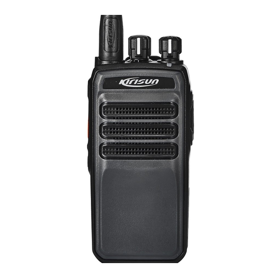
DP405 Service Manual Speaker PTT key Programmable key Belt clip Battery Battery latch 2.2. Programmable Keys To cater to your preference, you may have the programmable key defined as a shortcut key by the dealer through programming using the CPS (customer programming software). -
Page 7: Led Indication
DP405 Service Manual Repeater/Talkaround On the repeater channel, press this key to exit repeater mode. 2.3. LED Indication LED Indication Radio Status Red light on Emitting signals. Red light flashing Low-battery state. Green light on Receiving signals (e.g. voice and data), or channel activity detected. -
Page 8: Calling Back
DP405 Service Manual LED glows to indicate that carrier is received. When the selected channel is digital channel and when it received individual call, group call or all call, the radio will output the voice from the channel. When the channel is analogue channel and when it received analogue signals with CTCSS matching the one on this channel (or there is no CTCSS set on the channel), the radio will output voice form the channel. -
Page 9: Rx Principle
DP405 Service Manual RF Power Amplification Circuit RDA1846S outputs RF signal from pin 18 and enters first-level pre-drive amplifier (Q502) for initial amplification; then it enters second-level pre-drive amplifier (Q503) and drive amplifier (Q501) for further power amplification, ensuring sufficient drive power signal can be offered to final amplifier for ultimate power amplification;... -
Page 10: Power Section
DP405 Service Manual 4.4. Power Section 3.6V to supply power to PMU in AT1846S (i.e. RDA1846S) and HS8851 through DC-DC switch; 3M, 3C and USB3.3V output from PMU separately supplies power to other baseband circuits; the battery outputs 5V voltage through LDO and then outputs separate 5T and 5R after control by Q100 and Q102. -
Page 11: Port Description Of At1846S
DP405 Service Manual Modulation method of direct frequency synthesis TX filter based on digital signal processing technology TX modulation gain number is adjustable Digital voice activates TX control e. High-performance fractional PLL frequency synthesizer Fully-integrated in-chip RF VCO Fully-integrated internal loop filter ... -
Page 12: Port Description Of Master Chip Hs8851
DP405 Service Manual AVDD Power supply No connection RFOUT RF signal output No connection No connection AVDD Power supply PABIAS PA bias supply for PA AVDD Power supply Chip enable,high active; Chip sleep,low active GPIO7 Gpio7/vox(When Gpio7=VH, vox is active; else VL) - Page 13 DP405 Service Manual ADC_IN BAT_DET Battery capacity detection GPIO_D7 Input from side key GPIO_D6 BEEP_C Switch of voice receiving / alert tone GPIO_D101 EERROM_WP EEPROM AA17 GPIO_D24 ECN_3 Channel switch AB17 GPIO_D23 ECN_2 Channel switch GPIO_D11 KEYPAD5 4*4 keys GPIO_D99...
- Page 14 DP405 Service Manual GPIO_D25 UART_TXD1 Serial port 1 GPIO_D26 UART_RXD1 Serial port 1 GPIO_D74 TONE_OUT Output alert tone in PWM mode BATTERY Access of clock to button cell battery SINK1 SINK2 GPIO_D88 I2C_SDA EEPROM VOUT_D2 PMU_3M output GPIO_D87 I2C_SCL EEPROM...
-
Page 15: Function Description Of Semiconductor Devices
DP405 Service Manual GPIO_D20 ECO_0 Channel switch GPIO_D17 RED_LED Red LED control AUX_OUTP SPK+ Audio output after demodulation by LT1901 AUX_OUTN SPK- Transmit to HS8851 after reception and M_MICP AFDET demodulation by AT1846S M_MICN HP_MICN MIC1 Transmit MIC signals to HS8851... -
Page 16: Specifications
DP405 Service Manual Q500 RD07S2B TX final power amplification. DTA144EE APC output switch. Q507 3SK318 Receiver power amplifier. Q200 DTC144E Red LED driver. Q201 DTC144E Green LED driver. Q501 RD01MUS Transmitter power amplifier drive. Q601 DTC144E Audio power amplifier control switch. -
Page 17: Scan
DP405 Service Manual 5.2. Scan Enabling Scan Press the Scan programmable key to enable Scan and listen to activities on other channels. Press Scan key again to exit Scan. Scan List Each channel can be related to one “Scan List” though dealer programming. The radio can only start Scan on channels related with “Scan List”. -
Page 18: Tot (Time-Out-Timer
DP405 Service Manual Microphone Gain Microphone gain is the value based on which an audio level is amplified. You can adjust volume by setting a microphone gain. The higher the gain is, the higher the volume will be. Note: To avoid speech distortion, do not set a too high gain. -
Page 19: Setting
The radio has been set before delivery. However, to meet customers’ requirements, it may be necessary to set such digital functions as operating frequencies, channels, DT/DQT and automatic scan. This can be achieved by the programming software CPSM Vx.xx developed by Kirisun. It is user-friendly and easy to operate, and supports Chinese and English. - Page 20 DP405 Service Manual Note: While connecting the programming cable for the first time, please install its driver. (2) Double click the upgrade tool as shown below. DMR Software Upgrade Tool.exe Note: This tool upgrades firmware while retaining the original programming and calibration data.
-
Page 21: Assembly And Disassembly
DP405 Service Manual Start upgrade 6. Assembly and Disassembly This radio is a sophisticated communication device with precise and compact structure. Please be careful with the repair. 6.1. Installing/Uninstalling the Battery Installing the Battery (1) If he belt clip is installed, press the upper part of the belt clip (NO. 1 in the figure) gently so that it goes (2) Align the battery with the two battery slots on the upper part of the aluminum housing, and then insert the battery in the indicated direction (NO. -
Page 22: Installing/Uninstalling The Antenna
DP405 Service Manual 6.2. Installing/Uninstalling the Antenna Installing the Antenna Insert the whorled end of the antenna into the slot at the top of the radio, and turn the antenna clockwise to tighten it. Uninstalling the Antenna Hold the lower part of the antenna, and then turn it counterclockwise. -
Page 23: Detaching The Housing
DP405 Service Manual 6.4. Detaching the Housing (1) Detach the antenna; (2) Detach the two knobs and circlips; (3) Detach the two knob nuts and antenna nut; (4) Detach the two screws fastening the belt clip; (5) Insert the blade of a straight screwdriver into the battery slot of the aluminum-alloy holder, and prise the holder upwards until it goes up;... - Page 24 DP405 Service Manual (3) Unsolder the antenna using a soldering iron (or take down the antenna connector nut), and then separate the main board (including the PTT PCB) and the aluminum-alloy holder. Note: Take down the board gently so as to protect the welding of the PTT PCB.
-
Page 25: Explosion Diagram
DP405 Service Manual 6.6. Explosion Diagram Material Code Material Name Specification PC365,dual-color(black + 7MHP-4169-01B-W0 Front housing gray), etched, screen print 7MJS-4038-01A-W0 S760 spindle SUS304, original color 7MHP-4097-01A-W0 Earphone cover TPU, black, etched Cross recessed Material: hardened iron; Φ2mm*4mm, nickel plated,... - Page 26 DP405 Service Manual 6SS3-DC4140-B Battery Li-ion battery,7.4V, 2000mAh 6SS3-BJ4038-B Belt clip 1605 etching, coarse textured Cross recessed Material: hardened iron; Φ2.5mm*8mm,nickel plated, 7SMF-025080M-SZYB-Z1 mushroom-head machine screw metric coarse thread 7MHP-4169-02A-W0 Top cover PC365, black 7MHR-4038-05A-W0 Pogo-pin socket Silica gel, black, high-light...
-
Page 27: Tuning
DP405 Service Manual 7. Tuning 7.1. Tuning Method During the repair, if the components are replaced, you need to test and adjust the technical specification of the radio. 7.1.1. Parts for Tuning (1) Antenna interface converter (2) Universal interface 7.1.2. Tuning in PC Test Mode ... -
Page 28: Specification
DP405 Service Manual The specifications should be tested in the test mode: Rx Section 1. Sensitivity: <=-120dBm (0.25uV) (wide band, narrow band) 12dB SINAD 2. Distortion: <=5% 3. Current: static current :<=100mA; received working current: <=400mA 4. Squelch off Sensitivity: when RF input ≤-124dBm, squelch off. -
Page 29: Maintenance And Test Equipment
DP405 Service Manual 0.5W, @distortion ≤5%, 16Ω Audio Output Power ≤400mA Current Consumption (Rx) Transmitting Power 4W/1W@7.4V DC (Band U) ≤ ±2.5ppm Frequency Stability Maximum Modulation Offset ±5kHz/ ±2.5kHz ≤ 3% Modulation Distortion (300~3000Hz) ≤-60dBm/ ≤-50dBm Power of Adjacent Channel ≤-36dBm... -
Page 30: Troubleshooting
DP405 Service Manual Spectrum analyzer Measurement range: Max 1GHz DC or higher Center frequency: 50kHz~600MHz Trajectory generator Output voltage: 100mv or higher About 16Ω, 3W Dummy load Adjustable power supply 5V~10V, about 5A 10. Troubleshooting Failure Description Troubleshooting Startup fails A. -
Page 31: Appendix 1 Abbreviations
DP405 Service Manual Appendix 1 Abbreviations amplify, amplifier antenna automatic power control band pass filter CTCSS continuous tone control squelch system Digital code squelch DEMOD demodulation E2PROM electrically erasable programmable read only memory high pass filter instantaneous deviation control intermediate frequency... -
Page 32: Appendix 2 Material List(Electronic Section
DP405 Service Manual Appendix 2 Material List(Electronic section) Table 1 Material List of Main Board (400~470 MHz) Material Code Material Name Specification Position 133C07000002 Earphone jack 3.5mm, 4-pin, with switch, lead free 2RW3-RP08110SNJX RP08110SNJX-V01-0001, with Volume knob -V01 location column,lead free 2.5mm earphone,PJ-208B,4.5mm... - Page 33 DP405 Service Manual Battery 7MHP-4229-01A-W Beryllium copper connector Earphone-jack 7MIC-4038-01B-WC For 3.5mm earphone SMD rectifier rohm,1SR154-400,4.5mm*2.6mm*2. 1DR1-1SR154-400 D100 diode 0mm,-55℃ to 150℃ ESD9B5.0ST5G,5V,SOD923,lead 1DR1-ESD9B5 TVS diode D18,D19 free 1DR1-NSR1020MW2 SMD Schottky Semiconductor,NSR1020MW2T1G,S D101 barrier diode OD-323,2.7*1.35*1.0mm ROHM,1SS390,1.6mm*0.8mm*0.6m 1DS1-1SS390 D502,D503 switch diode m,-55℃...
- Page 34 DP405 Service Manual 1IS1-MCP4802-A D/A converter IC MICROCHIP,MCP4802 SMD switch MPS,MP2359,TSOT23-6,-40 to 1IS1-MP2359 IC102 power supply IC +85℃ 1IS1-TDA2822 SMD IC UTC,TDA2822,SOP8,-20 to +85℃ U600 1IS1-XC6204B502M SMD voltage XC6204B502MR,SOT-25,-40~85° IC100 regulator IC SMD Darlington 1TC1-UMC4 Rohm,UMC4N,UMT5,-~150℃ U301 tube SMD field effect...
- Page 35 DP405 Service Manual TOSHIBA,2SC5108-Y,2-2H1A,-~125 1TT1-2SC5108-Y R SMD transistor Q502 ℃ 1TT1-DTC144EE SMD transistor ROHM,DTC144EE,EMT3,-~150℃ Q103,Q200,Q201,Q4,Q7,Q10,Q606,Q707 1TT1-L2SC3356LT1 SMD transistor LRC,L2SC3356LT1,SOT-23,-~150℃ Q503 2CC1-10-C0G500-10 Multi-layer chip MURATA,GRM1555C1H100JA01D,1 capacitor 0,pF,±5%,50V,0402,C0G 2CC1-10-C0G500-10 Multi-layer chip MURATA,GRM1555C1H101JA01D,1 C24,C512 capacitor 00,pF,±5%,50V,0402,C0G 2CC1-10-C0G500-33 Multi-layer chip MURATA,GRM1555C1H330JA01D,3 C506,C521 capacitor 3,pF,±5%,50V,0402,C0G...
- Page 36 DP405 Service Manual 2CC1-10-X7R160-47 Multi-layer chip MURATA,GRM155R71C473KA01D, capacitor 47,nF,±10%,16V,0402,X7R 2CC1-10-X7R160-68 Multi-layer chip MURATA,GRM155R71C683KA88D, capacitor 68,nF,±10%,16V,0402,X7R 2CC1-10-X7R250-22 Multi-layer chip MURATA,GRM155R71E223KA61D, C584 capacitor 22,nF,±10%,25V,0402,X7R C120,C124,C39,C65,C66,C67,C68,C69,C71 ,C76,C77,C78,C79,C80,C81,C82,C83,C85, 2CC1-10-X7R500-10 Multi-layer chip MURATA,GRM155R71H102KA01D, C94,C96,C97,C98,C99,C100,C107,C125,C1 capacitor 1,nF,±10%,50V,0402,X7R 26,C127,C128,C129,C130,C133,C526,C536 ,C573,C581,R20 2CC1-10-X7R500-10 Multi-layer chip MURATA,GRM155R71H103KA88D, C110,C112,C115,C12,C17,C57,C58,C221,C capacitor 10,nF,±10%,50V,0402,X7R...
- Page 37 DP405 Service Manual 8,C541,C549,C550,C551,C552,C553,C554, C559,C564,C565,C21,C26,C333,C624,R25 2CC1-10-X7R500-47 Multi-layer chip MURATA,GRM155R71H472KA01D, C527 capacitor 4.7,nF,±10%,50V,0402,X7R 2CC1-10-X7R500-68 Multi-layer chip MURATA,GRM155R71H682KA88D, C55,R30 capacitor 6.8,nF,±10%,50V,0402,X7R 2CC1-10-Y5V160-10 Multi-layer chip murata,GRM155R61C105KA12D,1,u C95,C59 capacitor F,+80%/-20%,16V,1005,Y5V 2CC1-16-C0G500-12 Multi-layer chip murata,GRM1885C1H120JA01D,12, C508 capacitor pF,±5%,50V,1608,C0G 2CC1-16-C0G500-12 Multi-layer chip murata,GRM1885C1H121JA01D,12 C511 capacitor 0,pF,±5%,50V,1608,C0G...
- Page 38 DP405 Service Manual 2CC1-16-C0G500-4R Multi-layer chip murata,GRM1885C1H4R0CA01D,4, C516 capacitor pF,±0.25pF,50V,1608,C0G 2CC1-16-C0G500-5R Multi-layer chip murata,GRM1885C1H5R0CA01D,5, C513 capacitor pF,±0.25pF,50V,1608,C0G 2CC1-16-C0G500-6R Multi-layer chip murata,GRM1885C1H6R0CA01D,6, C515 capacitor pF,±0.25pF,50V,1608,C0G 2CC1-16-X7R500-47 Multi-layer chip murata,GRM188R71H471KA01D,47 L520 capacitor 0,pF,±10%,50V,1608,X7R 2CC1-20-X7R6R3-47 Multi-layer chip murata,GRM219R6J475KE19D,4.7,u C50,C51,C617 capacitor F,±10%,6.3V,2012,X7R 2CC1-20-Y5V160-10 Multi-layer chip...
- Page 39 DP405 Service Manual 2LH1-R501R5-L05-0 SMD air core E20.50*1.5*5TR L506 inductor Multi-layer chip SunLord,SDCL1608C22NJTDF,22,n 2LL1-16-22NJB L509,L511 inductor H,±5%,1608 Multi-layer chip SunLord,SDCL1608C2N7STDF,2.7,n 2LL1-16-2N7SA L504 inductor H,±2%,1608 SMD wire wound sagami,C1608CB-18NJ,18,nH,±5%, 2LW1-16UC-180J inductor 1608 SMD wire wound murata,LQW2BHNR22J03L,220,nH, 2LW1-20UC-221J L508 inductor ±5%,2012 SMD precision 2RE1-10-1003 1005,100K±1%...
- Page 40 DP405 Service Manual C32,R102,R109,R71,R72,R167,R11,R26,R2 yageo,RC0402JR-070RL,0,Ω,±5%,0 51,R252,C28,C569,C577,R17,R504,R516,R 2RS1-10-000O Chip resistor 555,C19,C27,C45,R1,R15,R32,R41,R43,R7 5,R624,R22,R21,IC301(pin2-3) yageo,RC0402JR-0710RL,10,Ω,±5% 2RS1-10-100J Chip resistor R66,R244,R559 ,0402 yageo,RC0402JR-07100RL,100,Ω,± 2RS1-10-101J Chip resistor 5%,0402 R108,R60,R236,R237,R238,R239,R3,R6,R1 yageo,RC0402JR-071KL,1KΩ,±5%,0 2RS1-10-102J Chip resistor 0,R502,R539,R544,R545,R547,R551,R623, R45,R340 yageo,RC0402JR-0710KL,10,KΩ,±5 R103,R110,R13,R40,R52,R53,R57,R58,R59 2RS1-10-103J Chip resistor %,0402 ,R68,R70,R245,R601,R614,R617 yageo,RC0402JR-07100KL,100,KΩ, 2RS1-10-104J Chip resistor R63,R526 ±5%,0402...
- Page 41 DP405 Service Manual yageo,RC0402JR-071K8L,1.8,KΩ,±5 2RS1-10-182J Chip resistor R618 %,0402 yageo,RC0402JR-0720KL,20,KΩ,±5 2RS1-10-203J Chip resistor C4,R529,C54,C73 %,0402 yageo,RC0402JR-0722RL,22,Ω,±5% 2RS1-10-220J Chip resistor R511 ,0402 yageo,RC0402JR-07220RL,220,Ω,± 2RS1-10-221J Chip resistor R249,R250 5%,0402 yageo,RC0402JR-072K2L,2.2,KΩ,±5 2RS1-10-222J Chip resistor R246,R247 %,0402 yageo,RC0402JR-0722KL,22,KΩ,±5 2RS1-10-223J Chip resistor R27,C34 %,0402 yageo,RC0402JR-07270RL,270,Ω,±...
- Page 42 DP405 Service Manual yageo,RC0402JR-0747RL,47,Ω,±5% 103 2RS1-10-470J Chip resistor R500 ,0402 yageo,RC0402JR-07470RL,470,Ω,± 104 2RS1-10-471J Chip resistor R14,R612,R615,R622 5%,0402 yageo,RC0402JR-074K7L,4.7,KΩ,±5 105 2RS1-10-472J Chip resistor R39,R561,R562 %,0402 yageo,RC0402JR-0747KL,47,KΩ,±5 R4,R227,R240,R241,R242,R243,R501,R50 106 2RS1-10-473J Chip resistor %,0402 8,R513,R540,R541,R557,R558,R61,R62 yageo,RC0402JR-07470KL,470,KΩ, 107 2RS1-10-474J Chip resistor C74,R83 ±5%,0402 yageo,RC0402JR-074R7L,4.7,Ω,±5...
- Page 43 DP405 Service Manual yageo,RC0402JR-076K8L,6.8,KΩ,±5 2RS1-10-682J Chip resistor R503 %,1005 yageo,RC0402JR-07820RL,820,Ω,± 2RS1-10-821J Chip resistor 5%,1005 yageo,RC0603JR-070RL,0,Ω,±5%,1 L100,L29,L30,L47,L48,L3,L6,L33,L510,R9,R 2RS1-16-000O Chip resistor 519,R44,R46,R602,R610 yageo,RC0603JR-072M2L,2.2,MΩ,± 2RS1-16-225J Chip resistor R517 5%,1608 yageo,RC0603JR-07270RL,270,Ω,± 2RS1-16-271J Chip resistor R515 5%,1608 yageo,RC0603JR-0756RL,56,Ω,±5% 2RS1-16-560J Chip resistor L513 ,1608 yageo,RC0603JR-0762KL,62,KΩ,±5 120 2RS1-16-623J...
- Page 44 DP405 Service Manual protection EVERLIGHT,19- 21SURC/S530-A 125 4PE1-16-F2 D203 2/TR8,0603,-40~ 85°C EVERLIGHT,H19 126 4PE1-16-F5 -213SYGC,0603, D205 -40~85°C L70,L104,L105,L8,L9,L10,L11,L12,L13,L14, L18,L31,L34,L35,L36,L37,L38,L39,L40,L41, 127 5FE1-BLM11A601S SMD EMI filter murata,BLM18AG601SN1D,1608.0 L42,L43,L44,L51,L52,L53,L54,L55,L56,L57, L58,L59,L60,L62,L63,L64,L67,L68,L300,L51 5,L521,L32,L600 128 5FE1-BLM21P300S SMD EMI filter murata,BLM21PG300SN1D,2012.0 L512,L514 Voltage controlled 5OT1-12R8-HHL-030 DSA321SCL,3.0V,12.8MHz±2.5ppm, temperature X500 -30℃~+75℃,3225...
- Page 45 DP405 Service Manual Power shield Copper-Nickel-Zinc alloy, 0.2 mm 132 7MDC-4207-04A-W cover thick, square, 16.2*15.1*2.3 Lead 133 9FSX-LF-RMAF8F2 Solder paste free,HF-RD8F2,Sn96.5-Ag3.0-Cu0.5 Ceramic YAGEO,CC0603JRNPO9BN680,68p 134 112C03000273 C510 capacitor F,±5%,50V,0603,NPO Ceramic CC0603KRX7R9BB102,1nF,±10%,5 135 112C03000367 C29,C42,C48,C52,C53,C60 capacitor 0V,1608,X7R 136 121I05000076 SMT IC AT1846S, lead free...
- Page 46 DP405 Service Manual OD-323,2.7*1.35*1.0mm ROHM,1SS390,1.6mm*0.8mm*0.6m 1DS1-1SS390 D502,D503 switch diode m,-55℃ to 125℃ ROHM,RN142S,1.6mm*0.8mm*0.6m 1DS1-RN142S D500,D501 switch diode m,-55℃ to 150℃ SMD universal memsic,MXD2020ML,LCC-8,5.0mm* 1ID1-MXD2020ML logic IC 5.0mm*1.99mm,-40℃ to 105℃ (accelerometer) JRC,NJM2904V,SSOP-8,-40℃ to 1IL1-NJM2904V SMD linear IC IC500,IC302 85℃ 1IS1-MCP4802-A D/A converter IC...
- Page 47 DP405 Service Manual SMD field effect transistor (for 1TF1-RD01MUS2-50 MITSUBISHI,RD01MUS2-501,S0T-8 portable digital Q501 9,-~150℃ and analog radios) 1TF1-RD07MUS2B-5 SMD field effect MITSUBISHI,RD07MUS2B-501,SLP, Q500 transistor -~150℃ SMD field effect TOSHIBA,SSM3K15AFS,2-2H1B,-~1 1TF1-SSM3K15AFS Q6,Q704 transistor 50℃ SMD field effect 1TF1-ST2301 ST2301,SOT-23-3L,-~150℃ Q102,Q20,Q600 transistor...
- Page 48 DP405 Service Manual 2CC1-10-C0G500-12 Multi-layer chip MURATA,GRM1555C1H120JA01D,1 C520 capacitor 2,pF,±5%,50V,0402,C0G 2CC1-10-C0G500-15 Multi-layer chip MURATA,GRM1555C1H150JA01D,1 C519,R504 capacitor 5,pF,±5%,50V,0402,C0G 2CC1-10-C0G500-15 Multi-layer chip MURATA,GRM1555C1H151JA01D,1 C573 capacitor 50,pF,±5%,50V,0402,C0G 2CC1-10-C0G500-1R Multi-layer chip MURATA,GRM1555C1H1R0CA01D, C135 capacitor 1,pF,±0.25pF,50V,0402,C0G 2CC1-10-C0G500-36 Multi-layer chip MURATA,GRM1555C1H360JA01D,3 C518 capacitor 6,pF,±5%,50V,0402,C0G 2CC1-10-C0G500-39 Multi-layer chip...
- Page 49 DP405 Service Manual 6V,0402,X7R 2CC1-10-X7R160-47 Multi-layer chip MURATA,GRM155R71C473KA01D, capacitor 47,nF,±10%,16V,0402,X7R 2CC1-10-X7R160-68 Multi-layer chip MURATA,GRM155R71C683KA88D, capacitor 68,nF,±10%,16V,0402,X7R 2CC1-10-X7R250-22 Multi-layer chip MURATA,GRM155R71E223KA61D, C59,C584 capacitor 22,nF,±10%,25V,0402,X7R C120,C124,C39,C65,C66,C67,C68,C69,C71 ,C76,C77,C78,C79,C80,C81,C82,C83,C85, 2CC1-10-X7R500-10 Multi-layer chip MURATA,GRM155R71H102KA01D, C94,C96,C97,C98,C99,C100,C107,C125,C1 capacitor 1,nF,±10%,50V,0402,X7R 26,C127,C128,C129,C130,C133,C526,C536 ,C581,R20 2CC1-10-X7R500-10 Multi-layer chip MURATA,GRM155R71H103KA88D, C110,C112,C115,C12,C17,C57,C58,C221,C capacitor 10,nF,±10%,50V,0402,X7R...
- Page 50 DP405 Service Manual capacitor 0,pF,±10%,50V,1005,X7R C231,C232,C233,C332,C522,C523,C528,C 530,C531,C532,C533,C535,C537,C538,C54 1,C549,C550,C551,C552,C553,C554,C559, C564,C565,C21,C26,C333,C624,R25 2CC1-10-X7R500-47 Multi-layer chip MURATA,GRM155R71H472KA01D, C527 capacitor 4.7,nF,±10%,50V,0402,X7R 2CC1-10-X7R500-68 Multi-layer chip MURATA,GRM155R71H682KA88D, C55,R30 capacitor 6.8,nF,±10%,50V,0402,X7R 2CC1-16-C0G500-12 Multi-layer chip murata,GRM1885C1H120JA01D,12, C142,C534 capacitor pF,±5%,50V,1608,C0G 2CC1-16-C0G500-15 Multi-layer chip murata,GRM1885C1H151JA01D,15 C145 capacitor 0,pF,±5%,50V,1608,C0G 2CC1-16-C0G500-16 Multi-layer chip...
- Page 51 DP405 Service Manual capacitor pF,±0.25pF,50V,1608,C0G 2CC1-16-C0G500-82 Multi-layer chip murata,GRM1885C1H820JA01D,82, C511 capacitor pF,±5%,50V,1608,C0G 2CC1-16-C0G500-8R Multi-layer chip murata,GRM1885C1H8R0BZ01D,8, C513 capacitor pF,±0.25pF,50V,1608,C0G 2CC1-16-C0G500-9R Multi-layer chip murata,GRM1885C1H9R0CA01D,9p C503 capacitor F,±0.25pF,50V,1608,C0G 2CC1-16-X7R500-47 Multi-layer chip murata,GRM188R71H471KA01D,47 L6,L520 capacitor 0,pF,±10%,50V,1608,X7R 2CC1-20-X7R6R3-47 Multi-layer chip murata,GRM219R6J475KE19D,4.7,u C50,C51,C617 capacitor F,±10%,6.3V,2012,X7R...
- Page 52 DP405 Service Manual inductor 2LH1-R401R5-R08-0 SMD air core E20.40*1.5*8TL L507 inductor Multi-layer chip SunLord,SDCL1608C27NJTDF,27,n 2LL1-16-27NJB L510 inductor H,±5%,1608 Multi-layer chip SunLord,SDCL1608C2N7STDF,2.7,n 2LL1-16-2N7SA L504 inductor H,±2%,1608 Multi-layer chip SunLord,SDFL1608LR10KTFB02,0. 2LL1-16-R10KA L509,L511 inductor 1,uH,±10%,1608 SMD wire wound sagami,C1608CB-47NJ,47,nH,±5%, 2LW1-16UC-470J L3,L69 inductor 1608 SMD wire wound sagami,C2012C-1R0J,1,uH,±5%,201...
- Page 53 DP405 Service Manual resistor ±1%,0603 SMD precision yageo,RC0603FR-07150KL,150,KΩ, 2RE1-16-1503 R518,R525 resistor ±1%,0603 SMD precision yageo,RC0603FR-07220KL,220,KΩ, 2RE1-16-2203 resistor ±1%,0603 C32,R102,R109,R71,R72,R167,R11,R26,R2 yageo,RC0402JR-070RL,0,Ω,±5%,0 51,R252,C28,C560,C569,C577,R17,R516,R 2RS1-10-000O Chip resistor 555,C19,C27,C45,R1,R15,R32,R41,R43,R6 24,IC301(pin2-3),R21,R75 yageo,RC0402JR-0710RL,10,Ω,±5% 2RS1-10-100J Chip resistor R66,R244,R559 ,0402 yageo,RC0402JR-07100RL,100,Ω,± 2RS1-10-101J Chip resistor 5%,0402 R108,R60,R236,R237,R238,R239,R3,R6,R1 yageo,RC0402JR-071KL,1KΩ,±5%,0 2RS1-10-102J...
- Page 54 DP405 Service Manual %,0402 2RS1-10-155J Chip resistor C109 yageo,RC0402JR-071K8L,1.8,KΩ,±5 2RS1-10-182J Chip resistor R618 %,0402 yageo,RC0402JR-0720KL,20,KΩ,±5 2RS1-10-203J Chip resistor C4,R529,C54,C73 %,0402 yageo,RC0402JR-0722RL,22,Ω,±5% 2RS1-10-220J Chip resistor R73,R511 ,0402 yageo,RC0402JR-07220RL,220,Ω,± 2RS1-10-221J Chip resistor R249,R250 5%,0402 yageo,RC0402JR-072K2L,2.2,KΩ,±5 2RS1-10-222J Chip resistor R246,R247 %,0402 yageo,RC0402JR-0722KL,22,KΩ,±5 2RS1-10-223J...
- Page 55 DP405 Service Manual yageo,RC0402JR-073K9L,3.9,KΩ,±5 2RS1-10-392J Chip resistor R632 %,0402 yageo,RC0402JR-0739KL,39,KΩ,±5 2RS1-10-393J Chip resistor R631 %,0402 yageo,RC0402JR-0747RL,47,Ω,±5% 100 2RS1-10-470J Chip resistor R500 ,0402 yageo,RC0402JR-07470RL,470,Ω,± 101 2RS1-10-471J Chip resistor R14,R612,R615,R622 5%,0402 yageo,RC0402JR-074K7L,4.7,KΩ,±5 102 2RS1-10-472J Chip resistor R39,R561,R562 %,0402 yageo,RC0402JR-0747KL,47,KΩ,±5 R4,R227,R240,R241,R242,R243,R501,R50 103 2RS1-10-473J...
- Page 56 DP405 Service Manual yageo,RC0402JR-0756KL,56,KΩ,±5 109 2RS1-10-563J R509,R38 %,0402 yageo,RC0402JR-07560KL,560,KΩ, 2RS1-10-564J Chip resistor ±5%,1005 yageo,RC0402JR-076K8L,6.8,KΩ,±5 2RS1-10-682J Chip resistor R503 %,1005 yageo,RC0402JR-07820RL,820,Ω,± 2RS1-10-821J Chip resistor 5%,1005 yageo,RC0603JR-070RL,0,Ω,±5%,1 L100,L29,L30,L47,L48,L33,R9,R519,R44,R4 2RS1-16-000O Chip resistor 6,R602,R610 yageo,RC0603JR-072M2L,2.2,MΩ,± 2RS1-16-225J Chip resistor R517 5%,1608 yageo,RC0603JR-07270RL,270,Ω,± 2RS1-16-271J Chip resistor...
- Page 57 DP405 Service Manual Littelfuse,0805L035,0603,-40 to 120 3FW1-0805L035 Fuse +85℃,CCC certified explosion F101 protection littelfuse,429003/433003/466003,321 121 3FW1-42932-302320 SMD fuse 6,3A/32V,CCC certified explosion F100 protection EVERLIGHT,19- 21SURC/S530-A 122 4PE1-16-F2 D203 2/TR8,0603,-40~ 85°C EVERLIGHT,H19 123 4PE1-16-F5 -213SYGC,0603, D205 -40~85°C L70,L104,L105,L8,L9,L10,L11,L12,L13,L14, L18,L31,L34,L35,L36,L37,L38,L39,L40,L41, 124 5FE1-BLM11A601S SMD EMI filter murata,BLM18AG601SN1D,1608.0...
- Page 58 DP405 Service Manual suite) 47.6*100.7,1.0,4.0,1.0,immersion Main board (U/V 128 6PM7-4169-HMF gold,CCC certified explosion band) protection Power shield Copper-Nickel-Zinc alloy, 0.2 mm 129 7MDC-4207-04A-W cover thick, square, 16.2*15.1*2.3 Ceramic YAGEO,CC0603JRNPO9BN680,68p 130 112C03000273 C141 capacitor F,±5%,50V,0603,NPO Ceramic CC0603KRX7R9BB102,1nF,±10%,5 131 112C03000367 C29,C42,C48,C52,C53,C60 capacitor...
- Page 59 DP405 Service Manual free Microphone for 139 4SM7-6027-A40B handheld EM6027MP2.8-C,-20~60°C two-way radio 140 7MHJ-4169-02A-W Conductive cloth 14*1.2*0.34 Single-compone 141 7MHJ-8088-01A-W 8088.0,250mL/pc nt epoxy glue 142 7MHP-1010-15A-W Microphone pad PVC, transparent Battery 143 7MHP-4229-01A-W Beryllium copper connector Earphone-jack 144 7MIC-4038-01B-WC For 3.5mm earphone...
- Page 60 DP405 Service Manual 4.75mm axis,M6 3SE3-RE08220HX-V Encoder switch thread,RE08220HX-V02-0000, lead free Microphone for 4SM7-6027-A40B handheld EM6027MP2.8-C,-20~60°C two-way radio 7MHJ-4169-02A-W Conductive cloth 14*1.2*0.34 Single-compone 7MHJ-8088-01A-W 8088.0,250mL/pc nt epoxy glue 7MHP-1010-15A-W Microphone pad PVC, transparent Battery 7MHP-4229-01A-W Beryllium copper connector Earphone-jack 7MIC-4038-01B-WC For 3.5mm earphone...
- Page 61 DP405 Service Manual barrier diode OD-323,2.7*1.35*1.0mm ROHM,1SS390,1.6mm*0.8mm*0.6m 1DS1-1SS390 D502,D503 switch diode m,-55℃ to 125℃ ROHM,RN142S,1.6mm*0.8mm*0.6m 1DS1-RN142S D500,D501 switch diode m,-55℃ to 150℃ SMD universal memsic,MXD2020ML,LCC-8,5.0mm* 1ID1-MXD2020ML logic IC 5.0mm*1.99mm,-40℃ to 105℃ (accelerometer) JRC,NJM2904V,SSOP-8,-40℃ to 1IL1-NJM2904V SMD linear IC IC500,IC302 85℃...
- Page 62 DP405 Service Manual SMD field effect transistor (for 1TF1-RD01MUS2-50 MITSUBISHI,RD01MUS2-501,S0T-8 portable digital Q501 9,-~150℃ and analog radios) 1TF1-RD07MUS2B-5 SMD field effect MITSUBISHI,RD07MUS2B-501,SLP, Q500 transistor -~150℃ SMD field effect TOSHIBA,SSM3K15AFS,2-2H1B,-~1 1TF1-SSM3K15AFS Q6,Q704 transistor 50℃ SMD field effect 1TF1-ST2301 ST2301,SOT-23-3L,-~150℃ Q102,Q20,Q600 transistor...
- Page 63 DP405 Service Manual 2CC1-10-C0G500-33 Multi-layer chip MURATA,GRM1555C1H330JA01D,3 C521 capacitor 3,pF,±5%,50V,0402,C0G 2CC1-10-C0G500-47 Multi-layer chip MURATA,GRM1555C1H470JA01D,4 C558,C560 capacitor 7,pF,±5%,50V,0402,C0G 2CC1-10-C0G500-68 Multi-layer chip MURATA,GRM1555C1H680JA01D,6 C518 capacitor 8,pF,±5%,50V,0402,C0G 2CC1-10-C0G500-6R Multi-layer chip MURATA,GRM1555C1H6R0CA01D, C520,C561 capacitor 6,pF,±0.25pF,50V,0402,C0G 2CC1-10-X7R100-10 Multi-layer chip 1005,1μF±10%,10V,X7R R607 capacitor 2CC1-16-C0G500-3R Multi-layer chip...
- Page 64 DP405 Service Manual 2CC1-10-X7R250-22 Multi-layer chip MURATA,GRM155R71E223KA61D, C584 capacitor 22,nF,±10%,25V,0402,X7R C120,C124,C39,C65,C66,C67,C68,C69,C71 ,C76,C77,C78,C79,C80,C81,C82,C83,C85, 2CC1-10-X7R500-10 Multi-layer chip MURATA,GRM155R71H102KA01D, C94,C96,C97,C98,C99,C100,C107,C125,C1 capacitor 1,nF,±10%,50V,0402,X7R 26,C127,C128,C129,C130,C133,C526,C536 ,C573,C581,R20 2CC1-10-X7R500-10 Multi-layer chip MURATA,GRM155R71H103KA88D, C110,C112,C115,C12,C17,C57,C58,C221,C capacitor 10,nF,±10%,50V,0402,X7R 222,C529,C539,C540,C49,C62,C612 2CC1-10-X7R500-15 Multi-layer chip MURATA,GRM155R71H153KA12D, C547,C545 capacitor 15,nF,±10%,50V,0402,X7R 2CC1-10-X7R500-18 Multi-layer chip MURATA,GRM155R71H182KA01D, capacitor 1.8,nF,±10%,50V,0402,X7R...
- Page 65 DP405 Service Manual 2CC1-10-X7R500-68 Multi-layer chip MURATA,GRM155R71H682KA88D, C55,R30 capacitor 6.8,nF,±10%,50V,0402,X7R 2CC1-10-Y5V160-10 Multi-layer chip murata,GRM155R61C105KA12D,1,u C95,C59 capacitor F,+80%/-20%,16V,1005,Y5V 2CC1-16-C0G500-10 Multi-layer chip murata,GRM1885C1H100JA01D,10, C507 capacitor pF,±0.5pF,50V,1608,C0G 2CC1-16-C0G500-12 Multi-layer chip murata,GRM1885C1H121JA01D,12 C511 capacitor 0,pF,±5%,50V,1608,C0G 2CC1-16-C0G500-15 Multi-layer chip murata,GRM1885C1H150JA01D,15, C509 capacitor pF,±5%,50V,1608,C0G 2CC1-16-C0G500-20 Multi-layer chip...
- Page 66 DP405 Service Manual 2CC1-16-X7R500-47 Multi-layer chip murata,GRM188R71H471KA01D,47 L520 capacitor 0,pF,±10%,50V,1608,X7R 2CC1-20-X7R6R3-47 Multi-layer chip murata,GRM219R6J475KE19D,4.7,u C50,C51,C617 capacitor F,±10%,6.3V,2012,X7R 2CC1-20-Y5V160-10 Multi-layer chip murata,GRM21BF51C106ZE15L,10, C10,C11,C103,C108,C119,C121,C123,C136 capacitor uF,+80%/-20%,16V,2012,Y5V ,C20,C106,C582,C25,C606,C615 2LG1-VLS3012ET-10 SMD power TDK,VLS3012ET-100M,10,uH,±20%, L107 inductor 3*3*1.2 2LH1-R401R5-R03-0 SMD air core E20.40*1.5*3TL L500 inductor 2LH1-R401R5-R04-0 SMD air core E20.40*1.5*4TL...
- Page 67 DP405 Service Manual SMD wire wound murata,LQW2BHNR22J03L,220,nH, 2LW1-20UC-221J L508 inductor ±5%,2012 SMD precision 2RE1-10-1003 1005,100K±1% R105,R107 resistor SMD precision YAGEO,RC0402FR-0716K2L,16.2,K 2RE1-10-1602 R106 Ω,±1%,0402 resistor SMD precision yageo,RC0402FR-0768KL,68,KΩ,±1 2RE1-10-6802 R104 resistor %,0402 SMD precision yageo,RC0603FR-07100KL,100,KΩ, 2RE1-16-1003 R527,R528 resistor ±1%,0603 SMD precision yageo,RC0603FR-07150KL,150,KΩ,...
- Page 68 DP405 Service Manual 0,R502,R539,R544,R545,R547,R551,R623, R45,R340 yageo,RC0402JR-0710KL,10,KΩ,±5 R103,R110,R13,R40,R52,R53,R57,R58,R59 2RS1-10-103J Chip resistor %,0402 ,R68,R70,R245,R601,R614,R617 yageo,RC0402JR-07100KL,100,KΩ, 2RS1-10-104J Chip resistor R63,R526 ±5%,0402 yageo,RC0402JR-071K5L,1.5,KΩ,±5 2RS1-10-152J Chip resistor R507 %,0402 yageo,RC0402JR-0715KL,15,KΩ,±5 2RS1-10-153J Chip resistor R512,R542 %,0402 2RS1-10-155J Chip resistor C109 yageo,RC0402JR-071K8L,1.8,KΩ,±5 2RS1-10-182J Chip resistor R618 %,0402 yageo,RC0402JR-0720KL,20,KΩ,±5...
- Page 69 DP405 Service Manual %,0402 yageo,RC0402JR-07270RL,270,Ω,± 2RS1-10-271J Chip resistor R505 5%,0402 yageo,RC0402JR-0733RL,33,Ω,±5% 2RS1-10-330J Chip resistor R510 ,0402 yageo,RC0402JR-0733KL,33,KΩ,±5 100 2RS1-10-333J Chip resistor R65,R67,C611,R18,R31,R616 %,0402 yageo,RC0402JR-073K9L,3.9,KΩ,±5 101 2RS1-10-392J Chip resistor R632 %,0402 yageo,RC0402JR-0739KL,39,KΩ,±5 102 2RS1-10-393J Chip resistor R631 %,0402 yageo,RC0402JR-0747RL,47,Ω,±5% 103 2RS1-10-470J...
- Page 70 DP405 Service Manual %,0402 yageo,RC0402JR-07510RL,510,Ω,± 109 2RS1-10-511J Chip resistor 5%,0402 yageo,RC0402JR-07560RL,560,Ω,± 2RS1-10-561J Chip resistor C578 5%,0402 yageo,RC0402JR-075K6L,5.6,KΩ,±5 2RS1-10-562J Chip resistor R613 %,0402 yageo,RC0402JR-0756KL,56,KΩ,±5 2RS1-10-563J Chip resistor R509,R38 %,0402 yageo,RC0402JR-07560KL,560,KΩ, 2RS1-10-564J Chip resistor ±5%,1005 yageo,RC0402JR-076K8L,6.8,KΩ,±5 2RS1-10-682J Chip resistor R503 %,1005 yageo,RC0402JR-07820RL,820,Ω,±...
- Page 71 DP405 Service Manual ,1608 yageo,RC0603JR-0762KL,62,KΩ,±5 120 2RS1-16-623J Chip resistor %,1608 yageo,RC0805JR-070RL,0,Ω,±5%,2 121 2RS1-20-000O Chip resistor C64,C605 yageo,RC1206JR-070R39L,0.39,Ω,± 122 2RS1-32-R39J Chip resistor R520,R521,R522,R523 5%,3216 Littelfuse,0805L035,0603,-40 to 123 3FW1-0805L035 Fuse +85℃,CCC certified explosion F101 protection littelfuse,429003/433003/466003,321 124 3FW1-42932-302320 SMD fuse 6,3A/32V,CCC certified explosion...
- Page 72 DP405 Service Manual 128 5FE1-BLM21P300S SMD EMI filter murata,BLM21PG300SN1D,2012.0 L512,L514 Voltage controlled 5OT1-12R8-HHL-030 DSA321SCL,3.0V,12.8MHz±2.5ppm, temperature X500 -30℃~+75℃,3225 compensated crystal oscillator HS8851 module HK MODULE +DP405W 130 61SL000007 (software burning UPGRADING SOFTWARE suite) 47.6*100.7,1.0,4.0,1.0,immersion Main board (U/V 131 6PM7-4169-HMF gold,CCC certified explosion...
- Page 73 DP405 Service Manual Table 4 Material List of Module Board Material Code Material Name Specification Position DP405W_MODULE_V2.0,36.4X24.7,4-layer,1.0m 136P04000009 Multi-layer PCB ROHM,RB521S30,SOD-523,1.6mm*0.8mm*0.6m 1DR1-RB521S30 Schottky barrier diode D1,D2 m,-40℃ to 125℃ MCU + baseband 1IS1-HS8851 HS8851;175;BGA;7.8X7.8;040;BB U2100 processing IC 1IS1-LN1121P332M SMD voltage regulator Natlinear,LN1121P332MR,SOT23-3,-40 to +85℃...
-
Page 74: Appendix 3 Material List (Structural Section)
DP405 Service Manual 2CC1-16-X5R160-1 Multi-layer chip murata,GRM188R61C105KA12D,1,uF,±10%,16V,1 C28,C39,C40 capacitor 608,X5R 2CC1-20-Y5V160-1 Multi-layer chip murata,GRM21BF51C106ZE15L,10,uF,+80%/-20 C1,C17,C18,C37,C38 capacitor %,16V,2012,Y5V 2RS1-10-000O Chip resistor yageo,RC0402JR-070RL,0,Ω,±5%,0402 R4,R68 2RS1-10-101J Chip resistor yageo,RC0402JR-07100RL,100,Ω,±5%,0402 R5,R6,R19 2RS1-10-102J Chip resistor yageo,RC0402JR-071KL,1KΩ,±5%,0402 C22,R3,R7,R8 R1,R2,R11,R12,R15,R16,R17,R 2RS1-10-103J Chip resistor yageo,RC0402JR-0710KL,10,KΩ,±5%,0402 2RS1-10-330J Chip resistor yageo,RC0402JR-0733RL,33,Ω,±5%,0402... - Page 75 DP405 Service Manual 6PD7-4038-HPC PTT plate 38*9.3, Version C,0.4,dual-side, FR-4 6SS3-MK4169-HMA Top housing assembly Dual-color (black + gray),white glue coated 7MBM-S4002-A Conductive foam Dual-sided adhesive, 12*7*7mm 7MHJ-4169-01A-W Dual-sided adhesive for PTT key 35*5*0.1 mm 7MHL-4141-01B-N Aluminum housing S8, ADC12, oiled jet...
- Page 76 DP405 Service Manual 7MHS-4072-08A-W STP knob circlip Stainless steel, T=0.3, original color 7MHZ-1731-01A-J5 Insulated paper for speaker 7NRC-060090035-W1 Coding nut Material: brass 7NRC-4078-01A-N Antenna connector nut Brass, black nickel plated surface 7PLP-4229-V01A Electrode sheet sticker PVC,0.3mm thick,11*11,single-sided adhesive Hardened iron, Φ2mm*4 mm, nickel plated, metric...
-
Page 77: Appendix 4 Accessory List
DP405 Service Manual Appendix 4 Accessory List Accessory Quantity Antenna Belt Clip Earphone Cover Charger Battery Belt Clip Screw Battery Charger Power Adaptor Antenna Strap Power adapator User Guide Warranty Card Strap... -
Page 78: Appendix 5 Schematic Diagrams And Layout Drawing
DP405 Service Manual Appendix 5 Schematic Diagrams and Layout Drawing Schematic Diagrams of Main Board IC100 XC6204B502MR L100 Q102 ST2301 C102 C101 R103 100nF C104 C103 R102 10uF/16V Q103 DTC144EE C105 RF_4V2 C108 BLM11A601S 10uF/16V L104 BLM11A601S L105 R104 56K 1%... - Page 79 DP405 Service Manual AF_VOL_IN RED_LED ENC_0 LDAC LDAC_PC/TV SPI_DA_OUT VOUTB PTT_KEY VCCN SPI_CLK GREEN_LED DACS_SW1 VOUTA ENC_1 K E Y P A D _ B L MCP4802 RDA_SQL R167 SPI_DA_OUT SPI_CLK C346 100nF SPI_/CS RDA_PDN AFCO_2 LDAC_PC/TV DACS_SW1 BLM11A601S BLM11A601S...
- Page 80 DP405 Service Manual ST2301A J200 NC R227 100K PTT_KEY R60 1K PF_KEY MAND_C C221 C222 R65 33K TOUT MAND DOUTY VREF DOUTX 100nF MXD2020ML S200 C332 MOD_RDA1846 R237 L300 E1_1 ENC_0 BLM11A601S R236 ENC_1 R239 E1_3 ENC_2 R238 IC301 E2_3...
- Page 81 DP405 Service Manual C145 C138 C140 C141 C142 C143 C144 C139 C503 C504 C505 C137 NC C510 D500 C511 RN142S C506 L500 2T 120P L501 3T L502 4T L503 3T Q500 C512 L504 L505 TO ANT RD07 100P 2.7nH D501...
- Page 82 DP405 Service Manual Q600 ST2301 R601 10uF/16V AFCO_1 DTC144EE F101 C603 Fuse R28 NC R61 47K R602 0Ω J600 C74 470K SSM3K15AFS T600 SPK+ C605 R603 0Ω C606 C604 10uF/16V 100nF R604 470K 470P 1000P INPUT2 OUTPUT2 4.7Ω C73 20K...
-
Page 83: Top-Layer Layout Drawing Of Main Board
DP405 Service Manual Top-Layer Layout Drawing of Main Board... -
Page 84: Bottom-Layer Layout Drawing Of Main Board
DP405 Service Manual Bottom-Layer Layout Drawing of Main Board... -
Page 85: Schematic Diagrams Of Module Board
DP405 Service Manual Schematic Diagrams of Module Board U2100-A DIGTAL 1 of 3 RF (VDD28) 5T_EN 5T_EN 5R_EN 5R_EN APC_SW1 PC_SW KEYPAD (VDD28) KEYOUT0 KEYOUT0 KEYOUT1 KEYOUT1 TP10 KEYOUT2 KEYOUT2 TP11 TP79 KEYOUT3 SPI LCM (VLCM) KEYOUT3 TP12 APC_SW2 FMARK... - Page 86 DP405 Service Manual 2520 封装 U2100-B VBAT_3V6 ANALOG 2 of 3 XO_P VOUT OUTPUT AUDIO MBIAS LN1121P332MR BT_TRX MIC_P MICP MICN MIC_N FM_LANT [2] HEADMIC_P HEADMICP FM_SANT [2] HEADMIC_N HEADMICN XO_N [2] HEADMIC_IN SPK_P TP65 HEADP_L [2] HE_L HEADP_R [2] HE_R...
- Page 87 DP405 Service Manual POWER VBAT_3V6 U2100-C POWER/GND 3 of 3 VBAT VB (FROM VBATB) VBATA (150mA) AVDDVBO AVDDVBVDDR AVDDVB VBATB LDO OUT (VBATB) (200mA) VDDRF VBATPA (150mA) VDD18 CHARGE (150mA) VDD28 VDD2V8 VBAT_SENSE VBAT_ADC (150mA) VDDCORE VDDCORE TP26 这个替换之前 3 号引脚...
-
Page 88: Layout Drawing Of Module Board
DP405 Service Manual Layout Drawing of Module Board...
Need help?
Do you have a question about the DP405 and is the answer not in the manual?
Questions and answers