Page 1
Professional wireless communication system solution supplier DP990/DP995 S ERV ICE M A NUA L ShenZhen Kirisun Communications Co.,Ltd. V190409...
This manual is intended for the maintenance and repair of the DP99X series frequency-modulated handheld radio, and can only be used by engineers and professional technicians who are trained by Kirisun. The parameters in this manual may vary with technology improvement, so for updated technical information, please contact Kirisun or its local dealers.
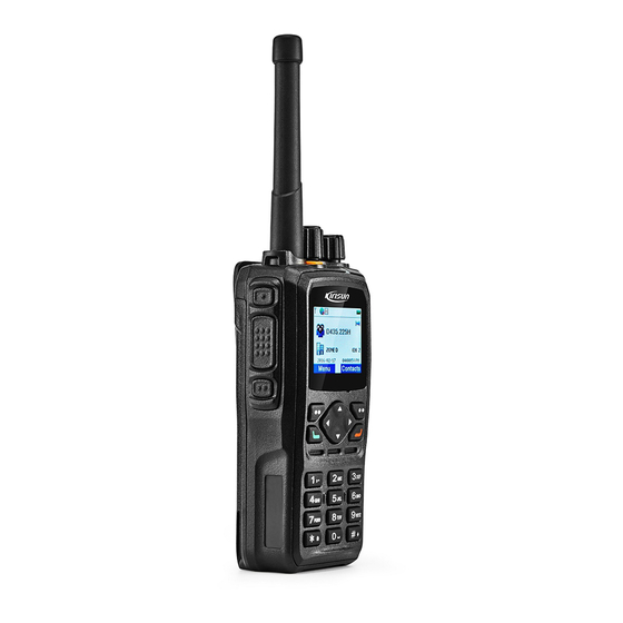
DP990/DP995service manual 2. Appearance and LED Indicator 2.1. Appearance DP990 Item Item Item Antenna Belt clip Up key Side key 1 Numeric key LCD screen PTT key Battery latch Audio accessory interface Side key 2 Battery LED indicator Menu/OK key...
DP990/DP995service manual DP995 Item Item Item Antenna Belt clip Audio accessory interface Side key 1 Battery latch LED indicator PTT key Battery Power/Volume knob Side key 2 Microphone Channel knob Speaker Cover screw Top key 2.2. LED Indicator LED State...
DP990/DP995service manual 3.2. Tx Circuit The TX circuit is mainly composed of three parts below. RF Power Amplification Circuit A carrier signal TX VCO generates is modulated and amplified before entering the Tx circuit, in which the signal passes a Π-type resistive attenuator to achieve inter-stage isolation between the PA circuit and the TX VCO, enters...
DP990/DP995service manual 3.3. Rx Circuit The Rx circuit is mainly composed of RF band-pass filters, a low-noise amplifier, a mixer, an IF filter, an IF amplifier and an IF processor. Front end of Rx circuit High-frequency signals from a low-pass filter pass an electrically tunable bandpass filter 1 the level TV1 controls for filtering out-of-band interference signals, and effective bandpass signals enter a low-noise amplifier (Q1205) for amplification.
DP990/DP995service manual The amplified signals the IF amplifier outputs enter the IF subsystem AD9864 (U1201) through its 47th pin for a second frequency mixing, upconverting the first IF signals to the second IF signals (2.25 MHz). The second IF signals are converted to digital signals through ADC sampling, and output through the SSI. The signals enter a DSP (OMAP-L138) for demodulation.
DP990/DP995service manual 3.5. GPS Circuit Positioning is achieved by the chip AT6558D-5N72. GPS/BDS signals are received by an antenna inductor, and then pass an HPF to filter Tx/Rx in-band signals. The band and harmonic spurious signals are further suppressed. Weak GPS/BDS signals pass a filter for frequency selection and then enter a GPS module for further amplification and filtered.
DP990/DP995service manual During power-off, the ON/OFF SWITCH is off, the input port PWR_SWITCH_DET detects a low-level power-on signal, and the output port PWR_CTL outputs a low level to turn off the PMOS. 3.6.2. Audio Circuit This circuit achieves audio input and output.
DP990/DP995service manual The radio employs an ADC (analog-digital converter) module, a security module, an SD card interface module, an accelerometer module, an LCD module, a key module, a BT module and an ultra-low power consumption RTC (AM18x5) module. The ADC module achieves low-battery alarm and VOX. The USB and UART interfaces reuse the same pin set. The USB port is reused by the radio and BT module.
DP990/DP995service manual Programming Radio Cable 3. Power on the PC. 4. Power on the radio. 5. Click to run the software. 6. In the main menu, click Read to read the parameters of the radio. 5. Assembly and Disassembly 5.1. Installing/Uninstalling the Battery...
DP990/DP995service manual 5.2. Installing/Uninstalling the Antenna To install the antenna, insert the antenna on the top of the radio and turn it clockwise until it is fastened. To uninstall the antenna, hold its lower part turn it counter-clockwise to loosen it.
DP990/DP995service manual 5.5. Detaching Main Board from Aluminum-Alloy Holder Step 1 Screw down the eight screws on the mainboard using a Phillips screwdriver. Step 2 Unsolder the motor wire using a soldering iron, and then take down the motherboard. 5.6. Detaching Key Board Step 1 Insert the thin point of a flat-headed screwdriver into the gap between the volume and channel knobs and the top housing, and prize and pull out the knobs.
DP990/DP995service manual b. In PC mode, go to [Low Tx Frequency] (F1~F8) and adjust the low Tx power to 0.8~1.2W. Max. Frequency Deviation a. In PC mode, go to [Max Frequency Deviation] and adjust the value to 4.8.0±0.05kHz. b. In PC mode, go to [Low Frequency Deviation] (F1~F8) and adjust the value to 4.8±0.05kHz.
Page 27
DP990/DP995service manual A. PLL crystal oscillator U9 is broken. Replace it. PLL fails B. Oscillator transistor is broken. Replace it. C.PLL chip U103 broken. Replace it. Communication fails A. Make sure the channels the both radios communicate on are of the same frequency.
DP990/DP995service manual Appendix 1 Material Lists and Schematic Diagrams (400~480 MHZ) Table 1 Material List (Electronic Part) Material Code Materia Name Unit Part NO. 6BLS-MS621FE Button cell BT100 61SM000259 DP990-02 mainboard C111,C128,C152,C200,C618,C61 2CC1-06-X7R500-10 SMD capacitor 9,C803,C804,C808,C1105,C400,C C428,C88,C1014,C1016,C1020,C 1021,C1022,C1023,C1026,C1059, 2CC1-06-C0G500-15 C1060,C1064,C1067,C1068,C106...
Page 36
DP990/DP995service manual 1IS1-MC74VHC1GT High-speed CMOS U110 analog switch IC Temperature 125O03000002 compensated crystal U201 oscillator 1IP1-OMAPL138EZ Dual-core CPU U401 CEA3 1IM1-IS43D16640C- DDR memory U500 1IS1-ADS1015 AD-to-IC converter U600,U602 1IS1-TLV320AIC14 CODEC chip U601 1IS1-LM4951ASD Audio amplifier U603 General-purpose 121I04000002 U604 linear IC...
Page 37
DP990/DP995service manual Front shield cover S1 7MDC-4182-01A-W of main board 7MDC-4207-04A-W Power shield cover Rear-side shield cover 7MDC-4127-03A-W P3,P5 of duplexer board 1 Rear-side shield cover 7MDC-4127-04A-W of duplexer board 2 Front shield cover S4 7MDC-4182-04A-W of main board Shield cover of...
Need help?
Do you have a question about the DP990 and is the answer not in the manual?
Questions and answers