NEC BladeServer Express5800 Series User Manual
Hide thumbs
Also See for BladeServer Express5800 Series:
- User manual (574 pages) ,
- Maintenance manual (238 pages) ,
- Installation manual (75 pages)

Related Manuals for NEC BladeServer Express5800 Series


Summary of Contents for NEC BladeServer Express5800 Series
- Page 1 NEC Express5800/BladeServer Series N8400-064AF/065AF/066AF/067AF NEC Express5800/120Bb-d6 User's Guide 1st Edition 4-2008 ONL-540_001_01-120Bb-d6-100-99-0803 456-01751-000 PN# 456-01751-000...
- Page 2 The NEC product(s) discussed in this document are warranted in accordance with the terms of the Warranty Statement accompanying each product. However, actual performance of each such product is dependent upon factors such as system configuration, customer data, and operator control.
- Page 3 Keep this User's Guide handy for quick reference when necessary. SAFETY INDICATIONS Follow the instructions in this User's Guide for your safety to use the server. The server contains components that may pose possible danger, hazards that may be caused by ignoring warnings, and preventive actions against such hazards.
- Page 4 Symbols used in this User's Guide and warning labels are listed below: Attentions Indicates that improper use may cause an electric shock. Indicates that improper use may cause fumes or fire. Indicates that improper use may cause fingers to be caught. Indicates that improper use may cause personal injury by the moving fan blades.
- Page 5 NOTE: This equipment has been tested and found to comply with the limits for a Class A digital device, pursuant to Part 15 of the FCC Rules. These limits are designed to provide reasonable protection against harmful interference when the equipment is operated in a commercial environment.
- Page 6 User's Guide, contact the service representative where you purchased this product. (5) NEC assumes no liability arising from the use of this product, nor any liability for incidental or consequential damages arising from the use of this User's Guide regardless of Item (4).
-
Page 7: Preface
PREFACE Welcome to the NEC Express5800/BladeServer series server. The NEC Express5800/BladeServer is the next generation of server technology that provides unparalleled performance. The server may be used as a workstation PC that configures a client-server system and provides high-speed processing and superior reliability. -
Page 8: About This User's Guide
Chapter 5 Installing the Operating System Describes how to install the operating system. Chapter 6 Installing and Using Utilities Describes how to install the utilities for the server. It also describes using the attached NEC EXPRESSBUILDER DVD-ROM. Chapter 7 Maintenance Provides nformation necessary to maintain successful operation of the CPU blade. -
Page 9: In The Package
Text Conventions The following conventions are used throughout this User's Guide. For safety symbols, see "SAFETY INDICATIONS" provided earlier. IMPORTANT: Items that are mandatory or require attention when using the server NOTE: Helpful and convenient piece of information IN THE PACKAGE The package contains various accessories, as well as the server itself. -
Page 10: Table Of Contents
CONTENTS Preface .............................. i About This User's Guide ........................ii In the Package ..........................iii Chapter 1 ........................... 1-1 Notes on Using Your Server .................... 1-1 Safety Notes ..........................1-2 For Proper Operation ........................1-6 Transfer to Third Party ......................... 1-8 Disposal and Consumables ...................... - Page 11 Making Backup Copies of System Information ................5-30 Installing with the OEM-FD for Mass Storage Device ............5-31 Chapter 6 ........................... 6-1 Installing and Using Utilities ................... 6-1 NEC EXPRESSBUILDER ......................6-1 Autorun Menu .......................... 6-5 Parameter File Creator ........................6-6 Parameters File ......................... 6-7 NEC ESMPRO ...........................
- Page 12 Lamps ............................8-6 Solving Problems ......................... 8-7 CPU Blade ..........................8-7 Problems with Windows ......................8-13 Problems with NEC EXPRESSBUILDER ................8-16 Problems with Express Setup ....................8-17 Problems with Parameter File Creator ................... 8-18 Collecting Event Log ......................... 8-19 Collecting Configuration Information ..................
- Page 13 Appendix B ........................B-1 Installing the Operating System ..................B-1 Setup and Re-setup of CPU Blade of Diskless Model ..............B-1 Local Installation ........................B-1 Remote Desktop for Management ..................... B-13 Setup of Device Driver (Normally Installed in Server) ............. B-14 Network Driver ........................
- Page 14 viii (This page is intentionally left blank.)
-
Page 15: Chapter 1
Chapter 1 Notes on Using Your Server This chapter includes information necessary for proper and safe operation of the server. - Page 16 NEC assumes no liability for any accident resulting in personal injury, death, or property damage if the server has been used in the above conditions.
-
Page 17: Notes On Using Your Server
Do not use any unauthorized interface cable. Use only interface cables provided by NEC and locate a proper device and connector before connecting a cable. Using an unauthorized cable or connecting a cable to an improper destination may cause a short circuit, resulting in a fire. - Page 18 1-4 Notes on Using Your Server...
- Page 19 Notes on Using Your Server 1-5 CAUTION Avoid installation in extreme temperature conditions. Immediately after the server is powered off, its internal components such as hard disk drives are very hot. Leave the server until its internal components fully cool down before installing/removing any component. Avoid contact with the server during thunderstorms.
-
Page 20: For Proper Operation
1-6 Notes on Using Your Server FOR PROPER OPERATION Observe the following notes for proper operation of the server. Failure to observe these notes may cause a malfunction of the server. CPU blade – N8400-064AF/065AF/066AF/067AF CPU blade assembly can be installed in the Blade Enclosure (SIGMABLADE). - Page 21 If the devices are used after storage or relocation, make sure that they are fully adapted to the operating environment. – It is recommended to use optional devices provided by NEC. Some memory devices and hard disk drives from other vendors are designed to be used with the server.
-
Page 22: Transfer To Third Party
1-8 Notes on Using Your Server TRANSFER TO THIRD PARTY The following must be observed when you transfer (or sell) the server and included software to a third party: Server Make sure to provide this manual along with the server to a third party. Provided Software To transfer or sell any software application that comes with the server to a third party, the following requirements must be satisfied:... -
Page 23: Disposal And Consumables
The server contains components that have limited lifetimes and require replacement. For stable operation of the server, NEC recommends you replace these components on a regular basis. Consult with your service representative for replacement these components. -
Page 24: User Support
1-10 Notes on Using Your Server USER SUPPORT If the server does not function correctly, do the following before requesting repair: Check that the power cord and the cables to other devices are properly connected. See Chapter 8 to check whether your problem is described. If it is, follow the recommended procedure to resolve it. - Page 25 Notes on Using Your Server 1-11 Advice for Health Prolonged use of a computer may affect your health. Keep in mind the following to reduce stresses on your body: Good Working Posture Sit in your chair with your back straight. If the desk height is correct, you will look down at the screen slightly and your forearms will be parallel to the floor.
-
Page 26: Chapter 2
Chapter 2 General Description This chapter provides information that you should be familiar with before using the server. It includes names and functions of the components and features of the server. -
Page 27: Overview
2-2 General Description OVERVIEW A BladeServer is a modular, multiprocessing system that includes a processor, memory, network connection, optional add-in card slot, and associated electronics on a single motherboard, which is called a CPU blade. A CPU bladeis typically installed into a rack-mountable enclosure that houses multiple CPU blades that share common resources, such as cabling, power supplies, and cooling fans. -
Page 28: Standard Features
Maintenance Features Self-diagnosis Off-line Maintenance Utility Power On Self-Test (POST) Memory dump feature using the DUMP Test and Diagnosis (T&D) switch Easy Setup NEC EXPRESSBUILDER (system management tools) SETUP (BIOS setup utility) LSI Software RAID Configuration Utility (RAID configuration utility) -
Page 29: Part Names And Controls
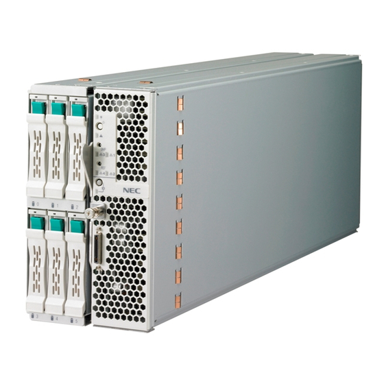
2-4 General Description PART NAMES AND CONTROLS This section describes the names and features of the components of the CPU blade. CPU Blade This section describes the names, installation positions, and features of the components of the CPU blade. Onboard Components Lithium battery DIMM socket #1, #5, #9, #2, #6, #10, #11, #7, #3, #12, #8, #4 from top... - Page 30 General Description 2-5 CPU Blade Access Side POWER lamp The lamp lights green when the CPU blade is powered on. The lamp lights amber when the CPU blade is powered off but power is supplied from the power supply unit. POWER switch The switch turns on or off the power of the CPU blade itself.
- Page 31 2-6 General Description ID switch Press this switch to turn on or off the ID lamp. ID lamp (blue) The lamp identifies the CPU blade in the system. The lamp is lit by a switch or software command. When the recognize command is received, the lamp blinks. If you press the ID switch, the lamp goes on.
- Page 32 General Description 2-7 External View Rear cover Front cover CPU blade with its cover installed DIMM CPU blade with its cover removed...
-
Page 33: Lamp Indications
2-8 General Description Lamp Indications This section describes the positions, indications, and descriptions of the lamps on the CPU blade and hard disk drive. CPU Blade The CPU blade includes five lamps. POWER lamp STATUS lamp LAN1 Link/Access lamp LAN2 Link/Access lamp ID lamp POWER Lamp The POWER lamp lights green while the power of the CPU blade is on. - Page 34 In addition, you can view detailed information on the error message on the virtual LCD when the STATUS lamp is flashing amber or red. You can use the virtual LCD through the Web browser of EXPRESSSCOPE engine (BMC) or NEC DianaScope Manager.
- Page 35 2-10 General Description Virtual LCD indications when STATUS lamp is flashing red On-screen message Description Action Proc 1 IERR An error was detected in CPU#1. 1. Turn off the power and then turn it on again. Proc 2 IERR An error was detected in CPU#2. 2.
- Page 36 General Description 2-11 On-screen message Description Action Battery Alm XX A battery voltage alarm was 1. Check the installation status of detected. the battery. XX=09: Upper limit alarm 2. Replace the battery. XX=02: Lower limit alarm Proc1 Vccp AlmXX A voltage alarm was detected. Replace the CPU blade.
- Page 37 2-12 General Description On-screen message Description Action Cooling Error In the Blade Enclosure, the number Check if the fans in the Blade of fans installed is insufficient or the Enclosure work normally. installed fan is faulty. Thus, the CPU Refer to the User’s Guide of the blade failed to power on due to Blade Enclosure to make sure that a insufficient cooling power.
- Page 38 If you press the ID switch, the lamp turns on. When the recognize command is received from management software such as NEC ESMPRO Manager and NEC DianaScope Manager, the lamp blinks.
-
Page 39: Using Your Server
2-14 General Description USING YOUR SERVER This section describes the basic operation of the blade server. Power-on of Blade Server There are two ways to turn on the power of the CPU blade. Turn on the power of the CPU blade after turning on the power of the display unit and peripherals connected to the CPU blade. - Page 40 BIOS SETUP Utility. Operation after Power ON If the CPU blade is connected to a display unit, the NEC logo appears on the screen of the display unit after power-on. While the NEC logo appears, the CPU blade runs the self-diagnosis program (POST). See "POST"...
-
Page 41: Power-Off Of Blade Server
ECC memory, CPU, keyboard, and mouse. POST also displays messages of the BIOS SETUP utility, such as the startup message, while in progress. With the factory setup of the CPU blade, the NEC logo appears on the display unit (if connected) while POST is in progress. To display the POST check results, press Esc. - Page 42 General Description 2-17 POST Execution Flow The following describes the progress of POST: IMPORTANT: Do not make unnecessary key entries or perform mouse operations while POST is in progress. Some system configurations that have an optional board installed may display the message "Press Any Key" to enter the board’s BIOS setup.
- Page 43 2-18 General Description If you have set the password using the BIOS SETUP utility, the password entry screen appears upon successful completion of POST. Up to three password entries will be accepted. Three incorrect password entries disable the system. In this case, turn off the power and wait about 30 seconds before turning it on again.
-
Page 44: Device Identification
General Description 2-19 Device Identification When more than one CPU blade of the same type is installed, use the ID lamp to identify the CPU blade requiring maintenance. The ID lamp is located on the CPU blade installed in the Blade Enclosure. The ID lamp also blinks blue when software commands from the management PC on the network are used. -
Page 45: Chapter 3
Chapter 3 Setting Up Your Server This chapter describes how to set up the server on a step-by-step basis. -
Page 46: Before Installing Cpu Blade
3-2 Setting Up Your Server BEFORE INSTALLING CPU BLADE Be sure to check the MAC addresses before installing a CPU blade in the Blade Enclosure. Check MAC Address A MAC address indicates the address specific for the network. It is a 12-digit alphanumeric string starting with "003013."... -
Page 47: Installing The Cpu Blade
Setting Up Your Server 3-3 INSTALLING THE CPU BLADE Install the CPU blade in a dedicated Blade Enclosure. Refer to the User's Guide of the Blade Enclosure for how to install the CPU blade. IMPORTANT: The CPU blade is extremely sensitive to static electricity. -
Page 48: Making Connections
3-4 Setting Up Your Server MAKING CONNECTIONS Connect peripheral devices to the CPU blade. IMPORTANT: Contact the maintenance engineer or your service representative for information on configuring an uninterruptible power supply system or auto power controller and the time schedule operation. If you are installing the CPU blade in the Blade Enclosure (SIGMABLADE), follow the instructions described in the User's Guide of the Blade Enclosure. - Page 49 IMPORTANT: To connect a peripheral or interface cable provided by a vendor other than NEC to the CPU blade, make sure that the device is compatible with the CPU blade. Some third party devices are not compatible with the CPU blade.
-
Page 50: Network
3-6 Setting Up Your Server USB Connection by K410-150(00) SUV Cable Connect the floppy disk drive, DVD-ROM drive, keyboard, and mouse according to the figure shown below. A USB hub should be self-powered if it is used. Use N8460-005. Display unit External floppy disk drive External DVD-ROM drive * Self-powered... -
Page 51: Configuring Your Server
Chapter 4 Configuring Your Server This chapter describes Basic Input Output System (BIOS) configuration. When you install the Bade Server for the first time or install/remove optional devices, read this chapter to understand the correct setup procedures. SYSTEM BIOS ~ SETUP ~ The SETUP utility is provided to configure the basic hardware settings of the CPU blade. -
Page 52: Starting Setup Utility
Starting SETUP Utility Powering on the CPU blade starts POST (Power On Self-Test) and displays its check results. If the NEC logo is displayed, press Esc. After a while, the following message appears at the bottom left of the screen: Press <F2>... -
Page 53: Description Of On-Screen Items And Key Usage
Configuring Your Server 4-3 Description of On-Screen Items and Key Usage Use the following keyboard keys to navigate the SETUP utility (the key functions are also listed at the bottom of the screen). Indicates the current menu. Indicates there are submenus. -
Page 54: Configuration Examples
Select [Boot] and specify the boot order. To display POST check results Select [Advanced] – [Boot-time Diagnostic Screen] – [Enabled]. You can also press Esc while the NEC logo is on the screen to display POST check results. To use the remote wake-up feature Via Modem: [Advanced] –... - Page 55 Configuring Your Server 4-5 Memory To pause POST if a memory error is detected Select [Advanced] – [Memory/Processor Error] – [Halt]. To check the installed memory (DIMM) status Select [Advanced] – [Memory Configuration] – [DIMM Group #1 - #2 Status] and check the status indications.
- Page 56 4-6 Configuring Your Server Security To set BIOS passwords Select [Security] – [Set Supervisor Password] and enter a password. Set the Supervisor password first, and then the User password. To enable/disable the POWER switch Select [Security] – [Power Switch Inhibit] – [Disabled]. Select [Security] –...
-
Page 57: Menu And Parameter Descriptions
Configuring Your Server 4-7 Menu and Parameter Descriptions The SETUP utility has the following six menus: Main Advanced Security Server Boot Exit To set specific functions, select a submenu from the above menus. The following describes the available options and their descriptions for each menu, as well as the factory-set values. Main Start the SETUP utility to display the Main menu. - Page 58 4-8 Configuring Your Server Processor Settings Select "Processor Settings" on the Main menu to display the following screen :...
- Page 59 Configuring Your Server 4-9 See the table below for the options and their descriptions: Option Parameter Description Your Setting Processor Retest [No] Clears the error information on the CPU. Processor Speed – Indicates the frequency of the CPU. Setting Processor 1 CPUID Numeral A numeral indicates the ID of processor 1.
- Page 60 [Disabled] Specify whether the self-diagnosis (POST) Diagnostic Screen screen is displayed or not at boot. Enabled If this item is set to "Disabled," the "NEC" logo appears during POST (pressing Esc displays the POST screen). Reset [No] Set this item to "Yes" to clear the...
- Page 61 Configuring Your Server 4-11 Memory Configuration Select "Memory Configuration" on the Advanced menu to display the following screen: See the table below for the options and their descriptions: Option Parameter Description Your Setting Memory Size – Indicates the total capacity of installed memory.
- Page 62 4-12 Configuring Your Server PCI Configuration Select "PCI Configuration" on the Advanced menu to display the following screen. Selecting a menu item preceded by the symbol "► and pressing Enter displays the submenu. " Option Parameter Description Your Setting Mezzanine Slot Enabled Specify whether the BIOS of the 1-2 Option ROM...
- Page 63 Configuring Your Server 4-13 Embedded NIC Select "Embedded NIC" on the PCI Configuration submenu to display the following screen: Option Parameter Description Your Setting LAN Port 1 - 2 [Enabled] Specify whether the BIOS of the Option ROM Scan on-board LAN controller is enabled or Disabled disabled.
- Page 64 4-14 Configuring Your Server Peripheral Configuration Select "Peripheral Configuration" on the Advanced menu to display the following screen: See the table below for the options and their descriptions. IMPORTANT: Make sure to avoid any conflicts in the interrupt requests or the base I/O addresses. If an assigned value is already used by another resource, it appears in yellow.
- Page 65 Configuring Your Server 4-15 Advanced Chipset Control Select "Advanced Chipset Control" on the Advanced menu to display the following screen: See the table below for the options and their descriptions: Option Parameter Description Your Setting Multimedia Timer [Disabled] Specify whether the multimedia timer is enabled or disabled.
- Page 66 4-16 Configuring Your Server Security Move the cursor onto "Security" to display the Security menu. These items are displayed only when the User Password is set.
- Page 67 Configuring Your Server 4-17 Select "Set Supervisor Password" or "Set User Password" and press Enter to display the following dialog box. Note that "Set User Password" is not available if the Supervisor password is not set. Enter a password of up to seven alphanumeric characters and symbols in this dialog box. IMPORTANT: "Set User Password"...
- Page 68 4-18 Configuring Your Server See the table below for the options and their descriptions: Option Parameter Description Your Setting Set User Up to 7 Press Enter to display the User password Password alphanumeric entry screen. With a User password, the characters available SETUP menus are restricted.
- Page 69 Configuring Your Server 4-19 Server Move the cursor onto "Server" to display the server menu. and pressing Enter displays the submenu. Selecting a menu item preceded by the symbol "► "...
- Page 70 5 minutes monitoring feature is enabled or 10 minutes disabled and the timer value. 15 minutes To use this feature, install NEC 20 minutes ESMPRO Agent. Do not use this 25 minutes feature if the system is booted 30 minutes...
- Page 71 Configuring Your Server 4-21 System Management Select "System Management" on the Server menu to display the following screen: See the table below for the options and their descriptions: Option Parameter Description Your Setting BIOS Revision – Indicates the version of BIOS. Board Part Number –...
- Page 72 4-22 Configuring Your Server Console Redirection Select "Console Redirection" on the Server menu to display the following screen: See the table below for the options and their descriptions: Option Parameter Description Your Setting BIOS Redirection [Disabled] Specify the serial port to which a Port hardware console is connected.
- Page 73 Configuring Your Server 4-23 Event Log Configuration Select "Event Log Configuration" on the Server menu to display the following screen: See the table below for the option and its description: Option Parameter Description Your Setting Press Enter to clear the system event Clear All Event –...
- Page 74 4-24 Configuring Your Server Boot Move the cursor onto "Boot" to display the Boot menu. The CPU blade searches for boot devices in the order set in this menu. The priority of the boot devices can be changed by using the ↑ ↑ ↑ ↑ , ↓ ↓ ↓ ↓ , +, and - keys. Move the cursor to the desired device with the ↑...
- Page 75 Configuring Your Server 4-25 Exit Move the cursor onto "Exit" to display the Exit menu. The following describes each option on the Exit menu: Exit Saving Changes Select this item to exit SETUP after saving the configuration changes in CMOS (non-volatile memory).
- Page 76 4-26 Configuring Your Server Load Setup Defaults Select this item to return all the values of SETUP to the default values. A confirmation screen appears. Select "Yes" to return the values to the default values. Select "No" to return to the Exit menu screen. IMPORTANT: The factory-set values of SETUP may be different from the default values depending on the model of the CPU blade.
- Page 77 Configuring Your Server 4-27 (This page is intentionally left blank.)
-
Page 78: Chapter 5
Chapter 5 Installing the Operating System with Express Setup This section describes information on using Express Setup to install and configure the following operating systems: Microsoft® Windows® Server 2003 R2 Standard Edition Microsoft® Windows® Server 2003 R2 Enterprise Edition To use the server with operating systems other than ones described in this section, contact your service representative. -
Page 79: About Express Setup
If you want to use the drivers located on the "OEM-Disk for Mass Storage Device" that ships with optional boards, a parameters file is required. You can create a parameters file in advance using "Parameter File Creator" included in NEC EXPRESSBUILDER. -
Page 80: Microsoft Windows Server 2003
Installing the Operating System with Express Setup 5-3 Microsoft Windows Server 2003 This section explains how to install Microsoft® Windows® Server 2003 by using Express Setup. NOTES: Express Setup does not support the installation of Windows Server x64 Editions. If you need to install it, see Appendix B. If you install Windows Server 2003 without using Express Setup, see Appendix B. - Page 81 – Operating system installation media (No Service Pack) Supported Mass Storage Controllers The NEC EXPRESSBUILDER DVD provided with the server supports the following mass storage controllers for installation: NOTE: If you want to install the operating system using a mass storage controller other than the ones listed below, see "Installing with...
- Page 82 Installing the Operating System with Express Setup 5-5 About the Hardware Components When you use Express Setup to install Windows Server 2003, make sure you observe the following instructions before beginning installation:. Installing on the Mirrored Volume If you want to install Windows Server 2003 on a volume that is mirrored using "Disk Management," invalidate the mirror volume and set it to a basic disk before installation.
- Page 83 5-6 Installing the Operating System with Express Setup About the System Partition Size The system partition size can be calculated from the following formula: Size necessary to install the system + Paging File Size + Dump File Size + Application Size Size necessary to install the system = 3500MB (Windows Server 2003 R2) Paging File Size (Recommended) = Mounted Memory Size * 1.5 Dump File Size...
-
Page 84: Flow Of Setup
Installing the Operating System with Express Setup 5-7 FLOW OF SETUP The following flow chart illustrates the setup procedures for Express Setup: Loading parameters (Step 2) Skip Next Select the operating system (Step 3) Next RAID configuration (Step 4) Next Windows Confirm Setting / Input (Steps 5 to 10) Next... -
Page 85: Installing Windows Server 2003
Turn on peripheral devices and then turn on the server. Insert the NEC EXPRESSBUILDER DVD into the optical disc drive of the server. Press the RESET switch or press Ctrl , Alt , and Delete to boot from the NEC EXPRESSBUILDER DVD. - Page 86 Installing the Operating System with Express Setup 5-9 The [Load parameters] steps are displayed. [Do not load parameters] (1) Select [Do not load parameters] if you do not have a parameters file. (2) Click [Next]. NOTE: If a floppy disk drive is not connected, select this item. [Load parameters] (1) Insert the floppy disk containing the parameters file.
- Page 87 You can use only the physical devices that have the same model number to configure a logical drive. If the process does not complete normally, the driver may not be stored in EXPRESSBUILDER. Refer to "Optional Board Supported by NEC EXPRESSBUILDER" described earlier in this chapter.
- Page 88 Installing the Operating System with Express Setup 5-11 Specify the installation medium and the Windows system partition. The [Specify medium / Partition] steps are displayed. Confirm the parameters, modify if necessary, and then click [Next]. IMPORTANT: About partition size – Specify a partition size larger than the required minimum size for operating system installation.
- Page 89 5-12 Installing the Operating System with Express Setup Enter the user information and client license mode. The [Enter basic parameters] steps are displayed. Confirm the parameters, modify if necessary, and then click [Next]. NOTE: Even if you do not enter an Administrator password, “...
- Page 90 Installing the Operating System with Express Setup 5-13 Enter the domain or workgroup name. The [Enter domain account] steps are displayed. Confirm the parameters, modify if necessary, and then click [Next]. Select the Windows components to install. The [Select Windows components] steps are displayed. Confirm the parameters, modify if necessary, and then click [Next].
- Page 91 5-14 Installing the Operating System with Express Setup Select the applications to install. The [Select applications] steps are displayed. Confirm the parameters, modify if necessary, and then click [Next]. Save the parameters. The [Save parameters] steps are displayed. If you want to save the parameters, insert a formatted floppy disk. Select [Save parameters], enter the file path of the parameters file in the text box, and click [Next].
- Page 92 Insert the CD-ROM or floppy disk containing the mass storage driver and proceed according to the messages. Remove the NEC EXPRESSBUILDER DVD from the optical disc drive according to the message. If you proceed with setup by using a parameters file, remove the floppy disk from the floppy disk drive.
- Page 93 5-16 Installing the Operating System with Express Setup Read the contents carefully and click [Yes] if you agree. If you do not agree, click [No]. IMPORTANT: If you do not agree to this license, setup terminates and Windows Server 2003 will not be installed. If the "NetWare Gateway (and Client) Service"...
-
Page 94: Installing And Setting Device Drivers
PROSet is necessary to utilize these features. Follow the procedure below to install PROSet: Insert the NEC EXPRESSBUILDER DVD into the optical disc drive. If the autorun menu appears, close the menu screen. Open [Windows Explorer]. -
Page 95: Network Driver
5-18 Installing the Operating System with Express Setup Network Driver Configure the settings of the network driver. The standard network driver will be installed automatically, but the link speed and Duplex mode need to be specified manually. [When PROSet is not installed] Open [Local Area Connection Properties]. -
Page 96: Optional Network Board Driver
Solving Problems" described later in this chapter. Optional Network Board Driver If you want to use the optional Network Board (N8403-017/020), install the driver stored on the NEC EXPRESSBUILDER DVD. The driver is in the following directory: "\001\win\winnt\dotnet\ns41s\pro1000\ws03xp2k" Refer to the installation procedure described in the section "Installation of the Optional Network Board Driver."... -
Page 97: Adapter Fault Tolerance (Aft)/Adaptive Load Balancing (Alb)
5-20 Installing the Operating System with Express Setup Adapter Fault Tolerance (AFT)/Adaptive Load Balancing (ALB) Adapter Fault Tolerance (AFT) is a feature that places more than one LAN controller on the same LAN (same segment), and automatically switches the process of the primary controller to the backup controller when any trouble occurs on the primary. - Page 98 Installing the Operating System with Express Setup 5-21 If it is necessary to set the adapter priority setting, refer to the following step. If it is not necessary, go to Step 7. 1. Click the [Settings] tab in [TEAM:xxx #yy Properties]. 2.
-
Page 99: Graphics Accelerator Driver
\001\win\winnt\dotnet\video\matrox\setup.exe Follow the messages to continue the installation. If the message "Digital Signature could not been found" appears, select [Yes] to continue. Remove the NEC EXPRESSBUILDER DVD from the optical disc drive and restart the system. Installing N8403-018 FibreChannel Controller If you use the FibreChannel Controller (N8403-018), update your system with the NEC EXPRESSBUILDER DVD. -
Page 100: Available Switch Options For Windows Server 2003 Boot.ini File
Installing the Operating System with Express Setup 5-23 Available switch options for Windows Server 2003 Boot.ini file Many different switche options are available for the Boot.ini file. For the available switch options, refer to the following information: Microsoft Knowledge Base - Article ID: 833721 "Available switch options for the Windows XP and the Windows Server 2003 Boot.ini files"... -
Page 101: Setting For Solving Problems
5-24 Installing the Operating System with Express Setup SETTING FOR SOLVING PROBLEMS Configure the following settings in advance to ensure quick recovery from system failures. Memory Dump (Debug Information) This section describes the procedures for collecting memory dump (debug information) on the server. - Page 102 Installing the Operating System with Express Setup 5-25 IMPORTANT: Windows Server 2003 x64 Editions [Complete memory dump] should be specified for writing debug information. However, if the mounted memory size is over 2GB, specify [Kernel memory dump]. You cannot specify [Complete memory dump].
- Page 103 5-26 Installing the Operating System with Express Setup IMPORTANT: Be sure to set the paging file size to more than the [Recommended] value in the operating system partition. If a value smaller than the [Recommended] value is set for [Initial Size] of the paging file, accurate debug information (memory dump) may not be collected.
-
Page 104: Windows Dr. Watson
Installing the Operating System with Express Setup 5-27 Windows Dr. Watson Dr. Watson is a debugger for application errors. When an application error occurs, Dr. Watson diagnoses the system and records the diagnostic information in a log file. Configure Dr. Watson to collect diagnostic information in the following procedure: Click [Run...] on the [Start] menu. -
Page 105: Network Monitor
5-28 Installing the Operating System with Express Setup Network Monitor A network monitor is useful for discovering the causes of network failures and determining the necessary steps to resolve them. To use a network monitor, you need to restart the system after installation. -
Page 106: Installing Maintenance Utilities
Installing the Operating System with Express Setup 5-29 INSTALLING MAINTENANCE UTILITIES Various maintenance utilities are contained on the NEC EXPRESSBUILDER DVD. See Chapter 6 for information on installing the utilities. UPDATING THE SYSTEM "Updating the System" is executed by Express Setup automatically. -
Page 107: Making Backup Copies Of System Information
Without the backup data, you will not be able to recover the information. You can save the information in the following procedure: Insert the NEC EXPRESSBUILDER DVD into the optical disc drive and reboot the system. Select [Tool menu (Normal mode)]. -
Page 108: Installing With The Oem-Fd For Mass Storage Device
Installing the Operating System with Express Setup 5-31 Installing with the OEM-FD for Mass Storage Device This section explains how to install a driver for a mass storage devices when using NEC EXPRESSBUILDER to install an operating system. If your mass storage device is not supported by NEC EXPRESSBUILDER, you must follow the procedure below.. -
Page 109: Chapter 6
Chapter 6 Installing and Using Utilities This section describes how to use the NEC EXPRESSBUILDER DVD to install utilities on your server. NEC EXPRESSBUILDER NEC EXPRESSBUILDER (hereafter referred to as EXPRESSBUILDER) helps you install the operating system and management software or use the maintenance utilities. -
Page 110: 6-2 Installing And Using Utilities
6-2 Installing and Using Utilities OS installation If you select this item, the Top menu appears. IMPORTANT: This tool is a configuration tool that is built on Windows PE 2.0 technology. Pay attention to the automatic reboot that occurs 72 hours after start. - Page 111 Installing and Using Utilities 6-3 Tool menu (Normal Mode) If you select this item, the Tool menu appears. You can use the following maintenance functions: – Maintenance Utility The Maintenance Utility is usually used by the service representative (see Chapter –...
- Page 112 6-4 Installing and Using Utilities Tool menu (Redirection Mode) If you want to operate the server via the BIOS redirection (the console-less function), select this item. NOTE: If you operate the server via the Remote KVM function, select the "Tool menu (Normal mode)." The menu's functions are the same as the "Tool menu (Normal Mode)."...
-
Page 113: Autorun Menu
Installing and Using Utilities 6-5 Autorun Menu When the EXPRESSBUILDER disc is inserted into the DVD drive, Windows automatically launches the menu shown below: From this menu you can do the following: Read the User's Guide or other documents. Update the server system (Windows drivers). Install the management software. -
Page 114: Parameter File Creator
Using a parameters file with Express Setup automates many of the installation steps of the operating system and system utilities. Also, you can reinstall the system with the same settings as before by using a parameter file. It is recommended to create a parameters file to setup the server with NEC EXPRESSBUILDER. -
Page 115: Parameters File
IMPORTANT: Do not remove the NEC EXPRESSBUILDER DVD from the drive during parameters file creation. Start the operating system. Insert the NEC EXPRESSBUILDER DVD into the optical disc drive. The NEC EXPRESSBUILDER menu appears. Click [Setup Windows]. A menu appears. - Page 116 6-8 Installing and Using Utilities Click [Parameter File Creator]. The Parameter File Creator appears.
- Page 117 Installing and Using Utilities 6-9 The [Load Parameters] step is displayed. Select [Do not load parameters] from the menu and click [Next]. Select the operating system to install. Select [Install the Windows (32bit editions)] from the menu and click [Next].
- Page 118 6-10 Installing and Using Utilities Enter the logical drive settings. The [Enter RAID setting] steps are displayed. Confirm the parameters, modify if necessary, and then click [Next]. IMPORTANT: "The number of the total physical devices displays the upper limit of devices that the RAID controller can support. The total of "The number of physical devices used to create the logical drive"...
- Page 119 Installing and Using Utilities 6-11 Specify the installation medium and the Windows system partition. The [Specify medium / Partition] steps are displayed. Confirm the parameters, modify if necessary, and then click [Next]. IMPORTANT: About partition size – Specify a partition size larger than the required minimum size for operating system installation.
- Page 120 6-12 Installing and Using Utilities Enter the user information and client license mode. The [Enter basic parameters] steps are displayed. Confirm the parameters, modify if necessary, and then click [Next]. IMPORTANT: A computer and user name are required. NOTE: Even if you do not enter an Administrator password, “...
- Page 121 Installing and Using Utilities 6-13 Enter the network protocol settings. The [Enter network protocol] steps are displayed. Confirm the parameters, modify if necessary, and then click [Next]. NOTE: The order of the network adapters may differ from the numbering of the LAN ports. Enter the domain or workgroup name.
- Page 122 6-14 Installing and Using Utilities Select the Windows components to install. The [Select Windows components] steps are displayed. Confirm the parameters, modify if necessary, and then click [Next] Select the applications to install. The [Select applications] steps are displayed. Confirm the parameters, modify if necessary, and then click [Next].
- Page 123 Installing and Using Utilities 6-15 Save the parameters. The [Save parameters] steps are displayed. If you want to save the parameters, insert a formatted floppy disk. Select [Save parameters], enter the file path of the parameters file in the text box, and click [Next].
- Page 124 6-16 Installing and Using Utilities The floppy disk containing the parameters file is created. Click [Yes] to exit the Parameter File Creator. NOTES: If you wish to edit an existing parameters file, click "Load Parameters" in the [Load Parameters] screen. Refer to help to edit the parameters file.
-
Page 125: Nec Esmpro
Usage threshold values can help the system administrator monitor and prevent server overloads. Supplement Note the following in addition to the NOTE that is described in the online document for NEC ESMPRO. About the Monitoring of Chassis Sensors The fan and power supply installed in the Blade Enclosure (SIGMABLADE) are monitored by the EM card. -
Page 126: Nec Dianascope
6-18 Installing and Using Utilities NEC DianaScope NEC DianaScope is an application that provides remote management of this server. See the online documents for details on the functions and installation of NEC DianaScope. NOTE: To manage this product using NEC DianaScope, a server license is required. -
Page 127: Maintenance
This chapter describes the daily maintenance of the CPU blade and precautions when relocating or storing it. MAKING BACKUP COPIES NEC recommends you make backup copies of your valuable data on a regular basis. For backup storage devices suitable for the CPU blade and backup tools, consult with your service representative. -
Page 128: System Diagnostics
7-2 Maintenance SYSTEM DIAGNOSTICS The system diagnostics run several tests on the CPU blade. Select [Tool menu] - [Test and diagnostics] in NEC EXPRESSBUILDER to diagnose the system. Test Items The following items are tested by the system diagnostics: Memory... -
Page 129: Startup And Exit Of System Diagnostics
LAN port of the Switch kit. Power on the CPU blade. Use the NEC EXPRESSBUILDER DVD to boot the system. Select [Tool menu (Normal mode)] when using the local console of the CPU. Select [Tool menu (Redirection mode)] when using the remote console. - Page 130 7-4 Maintenance Select [Test and diagnostics]. Select [End-User Mode]. The system diagnostics start. The system diagnostics take approximately three minutes to complete. When they are complete, the screen displays the following: Diagnostics tool title Test window title TeDoLi (TEst & Diagnosis On Linux) Ver001.00 (Build020901.1.1m) Test result Test End Start 10:06:58 End 10:09:58 Pass 000:03:00 TestTime 000:03:00...
- Page 131 Reboots the system. <Reboot> Select <Reboot> in the [Enduser Menu]. The CPU blade restarts and the system boots from the NEC EXPRESSBUILDER DVD. Exit NEC EXPRESSBUILDER and remove the DVD-ROM from the optical disc drive. Power off the CPU blade.
- Page 132 7-6 Maintenance (This page is intentionally left blank.)
-
Page 133: Chapter 8
Chapter 8 Troubleshooting If your CPU blade does not operate as expected, read this chapter before assuming a failure. NOTE: To prevent an unexpected failure, it is recommended to install NEC ESMPRO. -
Page 134: System Viewers
8-2 Troubleshooting SYSTEM VIEWERS You can monitor fault occurrences during system operation by using NEC ESMPRO. If any alert is reported to NEC ESMPRO Manager, it can viewed in the Operation Window, DataViewer, or AlertViewer of NEC ESMPRO Manager. [Example]... -
Page 135: Error Messages
Troubleshooting 8-3 ERROR MESSAGES If an error occurs on the CPU blade, an error message appears on the display unit connected to the CPU blade. POST Error Messages Powering on the CPU blade automatically starts the self-diagnostic program, POST (Power On Self-Test). - Page 136 8-4 Troubleshooting On-screen error message Action 0B70 The error occurred during temperature sensor Contact your service representative. reading 0B71 System Temperature out of the range The fan may be faulty or clogged with dust. Contact your service representative for maintenance. 0B74 The error occurred during voltage sensor reading Contact your service representative.
- Page 137 Troubleshooting 8-5 On-screen error message Action 0B96 BMC SDR Repository failure. Power off and reboot the CPU blade. If the error persists, contact your service 0B97 BMC SEL device failure. representative. 0B98 BMC RAM test error 0B99 BMC Fatal hardware error. 0B9A Management controller not responding 0B9B Private I2C bus not responding.
-
Page 138: Lamps
8-6 Troubleshooting LAMPS The CPU blade includes lamps to indicate the CPU blade status by using a variety of colors and display patterns on the front panel, hard disk drive, and power supply. See "Indications of STATUS lamp, their meanings and actions against the indications" in Chapter 2 for details. -
Page 139: Solving Problems
Troubleshooting 8-7 SOLVING PROBLEMS When the CPU blade does not operate as expected, see the following troubleshooting information before assuming a failure. If the CPU blade still fails to operate after following the troubleshooting information, note any error messages and contact your service representative. CPU Blade Fails to power-on: Is power supplied to the system? - Page 140 8-8 Troubleshooting Did you turn on the power of the Blade Enclosure at least 30 seconds after AC power is supplied to each power unit? → Initialization of BMC takes about 30 seconds after AC power is supplied to the CPU blade.
- Page 141 BIOS start message appears. Are memory and PCI devices that are incompatible with the CPU blade installed? → NEC cannot guarantee the operation of any devices other than those approved by NEC. "System Configuration Data Read Error" appears and POST pauses: Did you perform any of the following operations? –...
- Page 142 8-10 Troubleshooting Fails accessing internal or external devices (or such devices fail to operate): Are cables properly connected? → Make sure that the interface cables and power cord are properly connected. Also make sure that the cables are connected in the correct order. Is the power-on order correct? →...
- Page 143 Troubleshooting 8-11 Is the system used when Windows Server 2003 and Linux are not started? → Use the keyboard only when the USB floppy disk drive is not being accessed (the access lamp is off). – Press F6, S, and Enter in installation by using the Windows Setup Disk. –...
- Page 144 8-12 Troubleshooting Fails to start the operating system: Is the BIOS configuration correct? → Run the BIOS SETUP utility to change the boot order (see Chapter 4). Is a floppy disk in the floppy disk drive? → Remove the floppy disk and restart the CPU blade. Is the operating system damaged? →...
-
Page 145: Problems With Windows
Troubleshooting 8-13 Problems with Windows There are some cases where the following event log is registered when you install Windows Server 2003 x64 Editions: Source: DCOM Category: Error Event ID: 10016 Description: The application-specific permission settings do not grant Local Activation permission for the COM server application with CLSID {555F3418-D99E-4E51-800A-6E89CFD8B1D7} to the user{NT AUTHORITY\LOCAL SERVICE} SID {S-1-5-19}. - Page 146 For more details, refer to "Enabling Microsoft Windows Server 2003 R2 Hardware Management" on the following site: [NEC Express5800 Web Site] http://www.nec.co.jp/express/download/W2K3_R2 Cannot install the operating system correctly: Did you read the notes on installing the operating system? →...
- Page 147 Troubleshooting 8-15 The Telnet Service is not installed: Adjust the computer name to 14 characters or less before installing the telnet service. <How to install the Telnet Service> Click [Run] on the Start menu. Type "tlntsvr /service" in the [Open] box and click [OK]. Click the Start menu, click [Control Panel], click [Computer Management], and then click [Services] to check that the telnet service is registered.
-
Page 148: Problems With Nec Expressbuilder
8-16 Troubleshooting Problems with NEC EXPRESSBUILDER When the CPU blade will not boot from the NEC EXPRESSBUILDER DVD, check the following: Did you insert the NEC EXPRESSBUILDER DVD during POST and restart the CPU blade? → If you do not insert the NEC EXPRESSBUILDER DVD during POST and restart the CPU blade, an error message will appear or the operating system will boot. -
Page 149: Problems With Express Setup
Troubleshooting 8-17 Problems with Express Setup The system partition size issmaller than the specified value: → In Express Setup, there are some cases where the system partition size is c about 8MB smaller than the specified size. It is not a problem for normal system operation. The following message appears when you try to specify a partition size larger than the capacity of the hard disk drive: The creating of the partition was failed. -
Page 150: Problems With Parameter File Creator
8-18 Troubleshooting Problems with Parameter File Creator Fails to start Parameter File Creator: Parameter File Creator requires "Microsoft(R) HTML Application host" to run. → Parameter File Creator must be executed by “Microsoft® HTML Application host.” If this does not launch, follow the procedure below to associate Parameter File Creator with “Microsoft®... -
Page 151: Collecting Event Log
Troubleshooting 8-19 COLLECTING EVENT LOG This section describes how to collect the event logs of the CPU blade. IMPORTANT: If a STOP error, system error, or stall occurs, follow the procedure below after restarting the system. Restarting the system due to an error may display a message indicating insufficient virtual memory. -
Page 152: Collecting Configuration Information
8-20 Troubleshooting COLLECTING CONFIGURATION INFORMATION This section describes how to collect the hardware configuration information. "Diagnostic Program" is used to collect the information. IMPORTANT: If a STOP error, system error, or stall occurs, follow the procedure below after restarting the system. Click the Start menu and click [Control Panel]. -
Page 153: Memory Dump
Troubleshooting 8-21 MEMORY DUMP If an error occurs, the dump file should be saved to acquire necessary information. If you save the dump file to DAT, write that it is saved as "NTBackup" or "ARCServe" on the label. You can specify the location to save the diagnostic information. For more information, see Chapter IMPORTANT: Consult with your service representative before dumping the memory. -
Page 154: Recovery For Windows System
8-22 Troubleshooting RECOVERY FOR Windows SYSTEM If any file necessary for running the operating system is damaged, use the following procedures to recover the system. IMPORTANT: Make sure that the keyboard, display unit, DVD-ROM drive, and floppy disk drive are connected to the CPU blade. After recovering the system, see "Updating the System"... -
Page 155: Maintenance Tools
Start the Maintenance Tools according to the following procedure: Turn on the peripheral devices and then the server. Insert the NEC EXPRESSBUILDER DVD into the optical disc drive. Press Ctrl, Alt, and Delete to reboot the server. The Boot Selection menu is displayed. - Page 156 8-24 Troubleshooting Select "English." The tool menu is displayed. When you use a local console When you use a remote console Select a tool to start it.
-
Page 157: Function Of Maintenance Tools
The Off-line Maintenance Utility is started in Maintenance Utility. The Off-line Maintenance Utility is an operating system independent maintenance program. When you are unable to start the operating system dependent NEC ESMPRO to troubleshoot a problem, the Off-line Maintenance Utility can be used. - Page 158 This menu allows you to update the BIOS and firmware of the server by using an update disk (3.5-inch floppy disk) that is distributed by a NEC customer service representative. After rebooting the system, an update program is started automatically from the floppy disk, and the various BIOS and firmware programs are updated.
-
Page 159: Maintenance Tools With Remote Console
IMPORTANT: Do not use this feature on any computer other than the server, or on any other server without NEC EXPRESSBUILDER. Doing so may cause a failure of the server. Be sure to select [Tool menu (Redirection mode)] in the [Boot Selection] menu from the remote console. - Page 160 8-28 Troubleshooting NOTE: The following BIOS settings will be set as shown below: LAN Controller: [Enabled] Serial Port A: [Enabled] Base I/O Address: [3F8] Interrupt: [IRQ 4] Serial Port B: [Enabled] Base I/O Address: [2F8] Interrupt: [IRQ 3] BIOS Redirection Port: [Serial Port B] Baud Rate: [19.2K]...
-
Page 161: Resetting The Cpu Blade
Troubleshooting 8-29 RESETTING THE CPU BLADE This section describes how to reset the CPU blade when the CPU blade halts or when you want to restore the factory-set BIOS configuration. IMPORTANT: Resetting the CPU blade results in data loss if the operating system is running. -
Page 162: Forced Shutdown
8-30 Troubleshooting FORCED SHUTDOWN Use this function when an OS command does not shut down the CPU blade, the POWER switch does not turn off the CPU blade, or resetting does not work. Press and hold the POWER switch on the CPU blade for at least four seconds. The power is forcibly turned off. -
Page 163: Chapter 9
Make sure to use only optional devices and cables authorized by NEC. Repair costs of the server due to damage resulting from installation of such devices or cables will be charged even within the warranty period. -
Page 164: Safety Notes
9-2 Upgrading Your Server SAFETY NOTES Observe the following notes to install or remove optional devices safely: WARNING Observe the following instructions to use the server safely. Failure to follow these instructions may result in death or serious personal injury. See pages 1-2 to 1-5 for details. -
Page 165: Anti-Static Measures
Upgrading Your Server 9-3 ANTI-STATIC MEASURES The CPU blade contains electronic components sensitive to static electricity. Avoid damage caused by static electricity when installing or removing any optional devices. Wear a wrist strap (an arm belt or anti-static glove). Wear a wrist strap on your wrist. If no wrist strap is available, touch an unpainted metal part of the case before touching a component to discharge static electricity from your body. -
Page 166: Preparation For Installation
9-4 Upgrading Your Server PREPARATION FOR INSTALLATION To install or remove an optional device in the CPU blade, you should first remove the CPU blade from the Blade Enclosure. IMPORTANT: Remove the target CPU blade only. Do not remove any other blank covers or CPU blades from other slots. Be sure to install or remove the CPU blade carefully. -
Page 167: Installation/Removal Procedure
Do not operate the system until confirming that the second CPU is in the normal state. Make sure to use a CPU authorized by NEC. Installing a third-party CPU may cause a failure of the CPU as well as the server. Repair costs of the server due to damage resulting from installation of such a CPU will be charged even within the warranty period. - Page 168 9-6 Upgrading Your Server NOTE: If two CPU’s with different revision levels are installed on the server, the following message may appear in the System Log of the Event Viewer. However, it is not a problem for normal system operation:...
- Page 169 Upgrading Your Server 9-7 Installation Install the CPU in the following procedure: Shutdown the CPU blade and turn off the power. Remove the CPU blade from the Blade Enclosure. Refer to the User's Guide of the Blade Enclosure. Place the CPU blade on an anti-static sheet. Remove the two screws securing the rear cover.
- Page 170 9-8 Upgrading Your Server Confirm the location of the CPU socket. Remove the dummy heat sink and CPU cover from the socket. IMPORTANT: Keep the CPU cover for future use. Lift the socket lever. IMPORTANT: Open the lever fully. It can be opened 120 degrees or more.
- Page 171 Upgrading Your Server 9-9 Place the CPU in the socket carefully. NOTE: Note the direction of the CPU. To prevent the CPU from being inserted into the socket incorrectly, a pin mark is placed on the CPU and the socket. Check the pin marks to insert the CPU into the socket correctly.
- Page 172 Open "Device Manager. " If the "Computer" driver is set to "ACPI uni-processor PC" or "ACPI single-processor PC," change it to "ACPI multi-processor PC." Reboot the system and run NEC EXPRESSBUILDER in Windows to update the system. Perform the above procedure if –...
- Page 173 Upgrading Your Server 9-11...
- Page 174 9-12 Upgrading Your Server Removal To remove the CPU, follow Steps 1 through 6 of the installation procedure and perform Steps 7 through 15 in the reverse order. To remove the heat sink, remove the screws and gently slide it back and forth to loosen it.
-
Page 175: Dimm
For static notes, see the section "Anti-static Measures" described earlier. Make sure to use a DIMM authorized by NEC. Installing a third-party DIMM may cause a failure of the DIMM as well as the server. Repair costs of the server due to damage resulting from installation of such a DIMM will be charged even within the warranty period. - Page 176 9-14 Upgrading Your Server Adding Order and Precautions The DIMM’s must be populated in pairs. The DIMM’s in a pair must have the same capacity and speed. Check the labels on the DIMM’s. Install pairs of DIMM’s into slots as follows: –...
- Page 177 Upgrading Your Server 9-15 Firmly hold the cover, move it slightly toward the rear of the CPU blade, and then lift the cover to remove it. IMPORTANT: Handle the cover carefully so as not to make contact with any electronic devices on the CPU blade. Remove the four screws securing the front cover.
- Page 178 9-16 Upgrading Your Server Firmly hold the front cover and lift it straight up to remove it from the CPU blade. Open the levers at both ends of the DIMM socket. Push the DIMM into the socket. Key slot...
- Page 179 Upgrading Your Server 9-17 IMPORTANT: Use extreme care when installing a DIMM. Applying too much pressure can damage the socket. Keyed DIMM’s insert only one way. NOTE: Check the orientation of the DIMM. The connector of the DIMM is keyed to prevent incorrect insertion. If the DIMM is correctly inserted into the DIMM socket, the levers close automatically.
- Page 180 Remove the DIMM in the following procedure: NOTE: To remove the defective DIMM, check the error message appearing in POST or NEC ESMPRO to confirm the CPU blade where the DIMM is installed. Shutdown the CPU blade and turn off the power o.
-
Page 181: Mezzanine Card
Upgrading Your Server 9-19 Mezzanine Card The CPU blade can contain two mezzanine cards which allow network or file storage extension. To install a mezzanine card, use the mezzanine card slot on the CPU blade. The mezzanine card slot is factory-installed on the CPU blade. - Page 182 9-20 Upgrading Your Server Notes Note the following when installing or removing the mezzanine card. Be careful not to touch the terminals of the mezzanine card slot directly. Otherwise, the oil and dirt on your hands may adhere to the terminals and cause a contact failure. Set the optional ROM on the unbooted LAN device to "Disabled"...
- Page 183 Upgrading Your Server 9-21 Remove the two screws securing the rear cover. Firmly hold the cover, move it slightly toward the rear of the CPU blade, and then lift the cover to remove it. IMPORTANT: Handle the cover carefully so as not to make contact with any electronic devices on the CPU blade.
- Page 184 9-22 Upgrading Your Server From the top of the CPU blade, position the connector of the mezzanine card so that it aligns with the connector of the mezzanine card slot, and insert the mezzanine card into the slot. Type I Type II IMPORTANT: Do not touch the terminals on the board.
- Page 185 Upgrading Your Server 9-23 Removal To remove the mezzanine card, follow the procedure below: Shutdown the CPU blade and turn off the power. Remove the CPU blade from the Blade Enclosure. Refer to the User's Guide of the Blade Enclosure. Place the CPU blade on an anti-static sheet.
-
Page 186: Specifications
Appendix A Specifications NEC Express5800/120Bb-d6 Item N8400-064AF N8400-065AF N8400-066AF N8400-067AF Type Quad-core Quad-core Quad-core Dual-core Intel Xeon Intel Xeon Intel Xeon Intel Xeon processor processor processor processor X5460 L5420 E5405 X5260 Clock 3.16GHz... - Page 187 A-2 Specifications (This page is intentionally left blank.)
-
Page 188: Installing The Operating System
Use the keyboard only when the USB floppy disk drive is not being accessed (the access lamp is off). System update If the system configuration is modified, always update the system by using the NEC EXPRESSBUILDER DVD. See Chapter 6 for details. - Page 189 B-2 Installing the Operating System Re-installation to dynamic disk When reinstalling the operating system on a hard disk drive that is upgraded to a dynamic disk, one or more partitions may exist. If you wish to retain the partitions, note the following: <Example>...
- Page 190 Installing the Operating System B-3 Creating Partition Size For Windows Server 2003 x64 Editions: The system partition size can be calculated from the following formula: Size necessary to install the system + Paging File Size + Dump File Size + Application Size Size necessary to install the system = 4100MB Paging File Size (Recommended) = Mounted Memory Size * 1.5 Dump file Size...
- Page 191 B-4 Installing the Operating System For Windows Server 2003: The system partition size can be calculated from the following formula: Size necessary to install the system + Paging File Size + Dump File Size + Application Size Size necessary to install the system = 3500MB (Windows Server 2003 R2) Paging File Size (Recommended) = Mounted Memory Size * 1.5 Dump file Size...
- Page 192 Before beginning installation, prepare the following items: DVD-ROM drive Floppy disk drive NEC EXPRESSBUILDER (DVD-ROM) For Windows Server 2003 R2 x64 Editions – Microsoft Windows Server 2003 R2 Standard x64 Edition DISC 1 (CD-ROM) Microsoft Windows Server 2003 R2 Standard x64 Edition DISC 2 (CD-ROM) –...
- Page 193 B-6 Installing the Operating System Optional Board Supported by NEC EXPRESSBUILDER The NEC EXPRESSBUILDER DVD provided with the server supports the following mass storage controllers for installation: NOTE: If you want to install the OS using a mass storage controller other than the ones listed below, see "Installing with the OEM-FD for...
- Page 194 Drive A: * Press ENTER when ready. Insert the Windows Server 2003 x64 Edition OEM-DISK for NEC EXPRESSBUILDER into the floppy disk drive and press Enter. A list of the drivers for the mass storage devices is displayed.
- Page 195 B-8 Installing the Operating System IMPORTANT: The [Windows Setup] screen may not be displayed. Be sure to install Microsoft Windows Server 2003 R2 x64 Edition DISC 2 according to the following procedures. You can install Microsoft Windows Server 2003 R2 x64 Edition DISC 2 after the application of "System update."...
- Page 196 Follow the steps below to install and configure the device drivers. Installing Fibre Channel Controller Driver (N8403-018) If you use the FibreChannel Controller (N8403-018), update your system with the NEC EXPRESSBUILDER DVD. The Fibre Channel controller driver will be installed automatically.
- Page 197 Drive A: * Press ENTER when ready. Insert the Windows Server 2003 OEM-DISK for NEC EXPRESSBUILDER into the floppy disk drive and press Enter. A list of the drivers for the mass storage devices is displayed.
- Page 198 Installing the Operating System B-11 IMPORTANT: The [Windows Setup] screen may not be displayed. Be sure to install Microsoft Windows Server 2003 R2 DISC 2 according to the following procedures. You can install Microsoft Windows Server 2003 R2 DISC 2 after the application of "System update."...
- Page 199 Follow the steps below to install and configure the device drivers. Installing Fibre Channel Controller Driver (N8403-018) If you use the FibreChannel Controller (N8403-018), update your system with the NEC EXPRESSBUILDER DVD. The Fibre Channel controller driver will be installed automatically.
-
Page 200: Remote Desktop For Management
Installing the Operating System B-13 REMOTE DESKTOP FOR MANAGEMENT This section describes the necessary configuration settings of the Remote Desktop for Management for Windows Server 2003 x64 Editions or Windows Server 2003. IMPORTANT: The license for Sever Client Access is not needed to use the Remote Desktop for Management. -
Page 201: Setup Of Device Driver (Normally Installed In Server
B-14 Installing the Operating System SETUP OF DEVICE DRIVER (NORMALLY INSTALLED IN SERVER) For the installation and setup of each optional device driver, refer to the documentation provided with the device. Network Driver The two network drivers for the standard equipment are automatically installed. However, the transfer rate and duplex mode of each network driver must be set. - Page 202 Installing the Operating System B-15 When the system is Windows Server 2003 [When PROSet is not installed] Open [Local Area Connection Properties]. 1. Click [Start], click [Control Panel], click [Network Connections], and click [Local Area Connection]. Click [Configure]. The properties dialog box for the network adapter appears. Click the [Advanced] tab and specify [Link Speed &...
-
Page 203: Proset
PROSet is necessary to utilize these features. Follow the procedure below to install PROSet: When the system is Windows Server 2003 x64 Editions Insert the NEC EXPRESSBUILDER DVD into the DVD-ROM drive. Open [Windows Explorer]. Click [Start], click [Programs], click [Accessories], and click [Windows Explorer]. - Page 204 Installing the Operating System B-17 When the system is Windows Server 2003 Insert the NEC EXPRESSBUILDER DVD into the DVD-ROM drive. Open [Windows Explorer]. Click [Start], click [Programs], click [Accessories], and click [Windows Explorer]. Run "dxsetup.exe" in the following directory: \001\win\winnt\dotnet\ns41s\proset\2kxpws03 The [Intel(R) PROSet - Install Shield Wizard] starts.
-
Page 205: Graphics Accelerator
Remove the NEC EXPRESSBUILDER DVD from the DVD-ROM drive and restart the system. Fibre Channel Controller Driver If you use the FibreChannel Controller (N8403-018), update your system with the NEC EXPRESSBUILDER DVD. The Fibre Channel Controller driver will be installed automatically. -
Page 206: Optional Network Board Driver
Installing the Operating System B-19 Optional Network Board Driver If you want to use the optional Network Board (N8403-017/020), install the driver stored on the NEC EXPRESSBUILDER DVD. For Windows Server 2003, the driver is in the following directory: "\001\win\winnt\dotnet\ns41s\pro1000\ws03xp2k"... -
Page 207: Setup Of Adapter Fault Tolerance (Aft)/Adaptive Load Balancing (Alb
B-20 Installing the Operating System Setup of Adapter Fault Tolerance (AFT)/Adaptive Load Balancing (ALB) Adapter Fault Tolerance (AFT) is a feature that places more than one LAN controller on the same LAN (same segment), and automatically switches the process of the primary controller to the backup controller when any trouble occurs on the primary. - Page 208 Installing the Operating System B-21 When the system is Windows Server 2003 x64 Editions Open [Intel ® PROSet]. Click [Start], click [Control Panel], click [Administrative Tools], and click [Computer Management]. Double-click the [(Network Adapter Name)] in the Network Adapter list. Select the [Teaming] tab, check [Team with other adapters], and click [New Team...].
- Page 209 B-22 Installing the Operating System When the system is Windows Server 2003 Open [Intel ® PROSet]. Click [Start], click [Control Panel], click [Administrative Tools], and click [Computer Management]. Double-click the [(Network Adapter Name)] in the Network Adapter list. Select the [Teaming] tab, check [Team with other adapters], and click [New Team...]. The [New Team Wizard] dialog box appears.
-
Page 210: Re-Installation Of The Network Driver
Installing the Operating System B-23 RE-INSTALLATION OF THE NETWORK DRIVER When the system is Windows Server 2003 x64 Editions If you delete the network drivers, follow the procedure below to reinstall them: Restart the operating system. The [Upgrade Device Driver Wizard] dialog box appears. Click [Next]. - Page 211 B-24 Installing the Operating System When the system is Windows Server 2003 If you delete the network drivers, follow the procedure below to reinstall them: Restart the operating system. The [Upgrade Device Driver Wizard] dialog box appears. Click [Next]. Select the [Search for a suitable driver for my device (recommended)] radio button and click [Next].
-
Page 212: Setting For Solving Problems
Installing the Operating System B-25 SETTING FOR SOLVING PROBLEMS Configure the following settings in advance to ensure quick recovery from system failures. Memory Dump (Debug Information) - Windows Server 2003 - This section describes the procedures for collecting memory dump (debug information) on the server. - Page 213 B-26 Installing the Operating System IMPORTANT: Windows Server 2003 x64 Editions [Complete memory dump] should be specified for writing debug information. However, if the mounted memory size is over 2GB, specify [Kernel memory dump]. You cannot specify [Complete memory dump]. Specify a disk drive that has free space in excess of the memory size on the system +1MB or more.
- Page 214 Installing the Operating System B-27 Click [Settings] in the [Performance] box. The [Performance Options] window appears. Click the [Advanced] tab on the [Performance Options] window. Click [Change] in the [Virtual memory] box. Change the value set for [Initial Size] in the [Paging file size for selected drive] box to the [Recommended] value or more, and then click [Set].
-
Page 215: Dr. Watson
B-28 Installing the Operating System Dr. Watson Dr. Watson is a debugger for application errors. When an application error occurs, Dr. Watson diagnoses the system and records the diagnostic information in a log file. Configure Dr. Watson to collect diagnostic information in the following procedure: Click [Run...] on the [Start] menu. -
Page 216: Network Monitor
Installing the Operating System B-29 Network Monitor A network monitor is useful for discovering the causes of network failures and determining the necessary steps to resolve them. To use a network monitor, you need to restart the system after installation. It is recommended to install a network monitor before a failure occurs. From the [Start] menu, click [Control Panel]. -
Page 217: Re-Installing The Operation System If Multiple Logical Drives Exist
B-30 Installing the Operating System Re-installing the Operation System if Multiple Logical Drives Exist [Before Re-installing the Operation System] Be sure to make backup copies before reinstalling the operating system. [Re-installing the Operation System] Start a clean installation following the procedure described in this manual. Specify the partition where you want to install the operating system when the following message appears: The following list shows the existing partitions and... - Page 218 Installing the Operating System B-31 [Procedure for Modifying the Drive Letter] Modify the drive letter of the system or boot volume in the following procedure: Click [Start], right-click [My Computer], and select [Manage] to start [Computer Management]. Select [Disk Management] in the left side of the window. Right-click a volume and select [Change Drive Letter and Path...].
-
Page 219: Updating The System
Log on to the system as a user with administrator authority for the TS client. Insert the NEC EXPRESSBUILDER DVD into the DVD-ROM drive of the TS client. If the autorun menu appears on the TS client screen, close the menu. -
Page 220: Update From Ts Client (Windows Server 2003
Log on to the system as a user with administrator authority for the TS client. Insert the NEC EXPRESSBUILDER DVD into the DVD-ROM drive of the TS client. If the autorun menu appears on the TS client screen, close the menu. -
Page 221: Local Update
Local Update Log on to the system as a user with administrator authority. Insert the NEC EXPRESSBUILDER DVD into the DVD-ROM drive. Click "Setup Windows" in "Menu Items" and select [Update the System]. Follow the messages appearing on the screen.
Need help?
Do you have a question about the BladeServer Express5800 Series and is the answer not in the manual?
Questions and answers