
Related Manuals for aFe Power 52-10001D


Summary of Contents for aFe Power 52-10001D
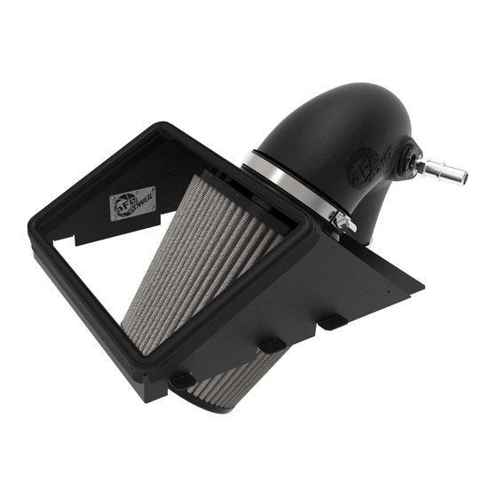
- Page 1 Rapid Induction Cold Air Intake System Instruction Manual P/N: 52-10001D / 52-10001R ______________________________ Make: Ford Model: Ranger Year: 2019-2021 Engine: L4-2.3L (t)
- Page 2 • Please read the entire instruction manual before proceeding. • Ensure all components listed are present. • If you are missing any of the components, call customer support at 951-493-7100. • Ensure you have all necessary tools before proceeding. • Do not attempt to work on your vehicle when the engine is hot. •...
- Page 3 A1/A2 Page 3...
- Page 4 REMOVAL Figure A Refer to Figure A for Steps 1-4 Step 1: Using a panel clip remover or flat head screwdriver, remove the coolant line 1 attached to the factory intake tube. Step 2: Disconnect the vent hose 2 from the factory upper intake tube. Step 3: Disconnect the air temperature sensor 3 .
- Page 5 REMOVAL Figure B Refer to Figure B for Step 5 Step 5: Release the 3 clamps 5 on the back of the factory housing and remove the factory upper housing along with the factory air filter. Page 5...
- Page 6 Refer to Figure C for Steps 6-7 Step 6: Remove the filter clamp 6 from the aFe POWER air filter. Slip the aFe POWER Air Filter onto the aFe POWER housing, snapping the filter in place. Place the clamp back on the filter flange.
- Page 7 Figure D Refer to Figure D for Steps 8-9 Step 8: Install the rubber grommet and air temp sensor fitting 8 onto your aFe POWER intake tube as shown. *NOTE: Use a dab of oil or dish soap on the air temp sensor fitting to help install into rubber grommet.
- Page 8 INSTALL Figure C Refer to Figure C for Step 10 Step 10: Remove the air intake temperature sensor 10 from your factory housing and set aside. Page 8...
- Page 9 Figure D Refer to Figure D for Steps 11-12 Step 11: Install the air intake temperature sensor 11 removed from step 10 onto the aFe POWER intake tube. Step 12: Install the silicone wrapped coupling 12 onto your aFe POWER intake tube along with the supplied clamp (#048) and tighten.
- Page 10 Step 13: Install the aFe POWER intake tube assembly into the vehicle beginning at the air filter. Step 14: Slip the aFe POWER intake tube onto the turbo inlet 13 along with the clamp (#048). Step 15: Align the aFe POWER intake tube and coupler, then tighten the clamps 14 using an 8mm nut driver.
- Page 11 INSTALL Figure F Refer to Figure F for Steps 16-18 Step 16: Plug in the air temperature sensor 14 . Step 17: Re-connect the vent hose 15 from step 2. *(If difficult, re-connect before step 13.) Step 18: Your installation is now complete. NOTE: Check all screws, clamps, and connectors are secure after 100-200 miles.
- Page 12 Page Left Blank Intentionally Page 12...
- Page 13 Page Left Blank Intentionally Page 13...
- Page 14 Pro DRY S Air Filter Pro 5R Air Filter Dynamic Air Scoop BladeRunner Intercooler Tubes P/N: 21-90113 P/N: 24-90113 P/N: 54-13056S (Blk) P/N: 46-20384-B 54-13056SL (Blue) 54-13056SR (Red) Pro DRY S Restore Kit Blue Squeeze Restore Kit Twisted Steel Down Pipe w/ Cat Spring Booster V3 P/N: 90-59999 P/N: 90-50501...
-
Page 15: Warranty
To purchase any of the items above, view airflow charts, dyno graphs, photos, and video; please go to aFepower.com. Warranty General Terms: • aFe warrants their products to be free from manufacturer’s defects due to workmanship and material. • This warranty applies only to the original purchaser of the product and is non-transferrable. •... - Page 16 252 Granite Street Corona, CA 92879 TEL: 951.493.7100 • TECH: 951.493.7185 E-Mail:Tech@aFepower.com P/N: 06-81396...
Need help?
Do you have a question about the 52-10001D and is the answer not in the manual?
Questions and answers