
Related Manuals for aFe Power 57-10018D


Summary of Contents for aFe Power 57-10018D
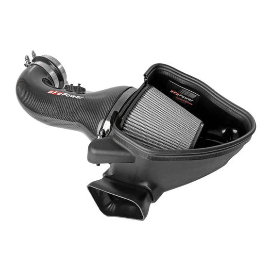
- Page 1 Cold Air Intake System Instruction Manual P/N: 57-10018D / 57-10018R _____________________________ Make: Chevrolet Model: Camaro ZL1 Year: 2017-2023 Engine: V8-6.2L (sc) LT4...
- Page 2 • Please read the entire instruction manual before proceeding. • Ensure all components listed are present. • For technical support please call 951-493-7185. • Ensure you have all necessary tools before proceeding. • Do not attempt to work on your vehicle when the engine is hot. •...
- Page 3 Page 3...
- Page 4 REMOVAL Figure A Refer to Figure A for Steps 1-4 Step 1: Disconnect the mass air flow sensor 1 and the wiring harness clip 2 . Step 2: Disconnect the breather hose 3 from the intake tube. Step 3: Use an 8mm nut driver to loosen the stock clamps 4 at the throttle body and the airbox. Step 4: Remove the stock intake tube.
- Page 5 REMOVAL Figure B Refer to Figure B for Steps 5-6 Step 5: Remove the clip 5 holding the coolant line to the airbox. Step 6: Remove the airbox by pulling up to release from its mounting grommets 6 . Make sure the mounting grommets are still in the chassis mounting tabs.
- Page 6 Step 7: Using a Torx T20 driver, remove the mass air flow sensor 7 from the upper half of the airbox and install it into the aFe POWER intake tube using the two provided M4 torx screws. Step 8: Install the supplied aluminum vent fitting 8 into the aFe intake tube using a 15mm wrench or adjustable wrench.
- Page 7 Make sure the pins are completely through the mounting grommets and the scoop is in the rubber inlet opening cavity. Step 11: Install the seal trim 10 on the top opening of the aFe POWER housing as shown. Trim to fit. Page 7...
- Page 8 Refer to Figure E for Step 12 Step 12: Remove the filter clamp 11 from the aFe POWER filter. Slide the aFe POWER filter into the aFe POWER housing from the top. Then guide the filter flange through the oval opening in the housing and snap in the filter.
- Page 9 INSTALL Figure F Refer to Figure F for Steps 13-14 Step 13: Install the supplied silicone coupling 12 onto the throttle body with the supplied clamp 13 as shown and tighten the clamp using an 11mm deep socket and driver. Step 14: Place the other supplied clamp 14 on the silicone coupling as shown.
- Page 10 Figure G Refer to Figure G for Steps 15-16 Step 15: Install the aFe POWER intake tube into the vehicle. Slide the tube into the throttle body coupling first, then into the air filter. Step 16: Align the aFe POWER intake tube and clamps correctly, then using a 11mm deep socket and driver tighten all the clamps.
- Page 11 Step 17: Connect the mass air flow sensor 15 and breather hose 16 . Step 18: Check all the components are tight and secure. Your installation is now complete. Thank you for choosing aFe POWER! NOTE: Check all bolts, clamps, and connectors after 100-200 miles.
- Page 12 252 Granite Street Corona, CA 92879 https://afepower.com/contact P/N: 06-81445...
Need help?
Do you have a question about the 57-10018D and is the answer not in the manual?
Questions and answers