
Related Manuals for aFe Power takeda 56-70043D


Summary of Contents for aFe Power takeda 56-70043D
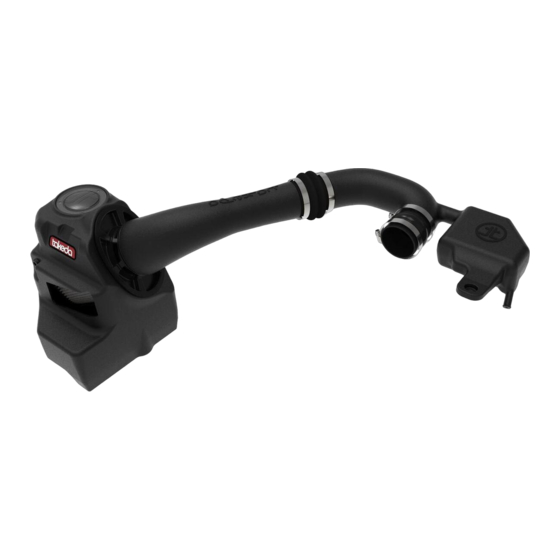
- Page 1 Takeda Momentum Cold Air Intake System Instruction Manual P/N: 56-70043D / 56-70043R ______________________________ Make: Subaru Model: Impreza Year: 2012-2016 Engine: H4-2.0L...
- Page 2 • Please read the entire instruction manual before proceeding. • Ensure all components listed are present. • If you are missing any of the components, call customer support at 951-493-7100. • Ensure you have all necessary tools before proceeding. • Do not attempt to work on your vehicle when the engine is hot. •...
- Page 3 A1/A2 Page 3...
- Page 4 REMOVAL Figure A Refer to Figure A for Steps 1-2 Step 1: Using a flat head screwdriver or panel clip removal tool, remove the two panel clips 1 holding on the air scoop. Step 2: Remove the air scoop from the vehicle and set aside. Page 4...
- Page 5 REMOVAL Figure B Refer to Figure B for Step 3-6 Step 3: Using a flat head screwdriver or panel clip removal tool, remove the panel clip 2 from the intake tube mount. Step 4: Using a pair of pliers, squeeze the spring clamp 3 and remove the crankcase vent hose from the intake tube.
- Page 6 REMOVAL Figure C Refer to Figure C for Steps 7-9 Step 7: Using a 10mm nut driver, remove the screw 7 from the airbox mount. Set aside screw for later use. Step 8: Using a 10mm wrench, remove the nut 8 from the airbox bushing mount. Step 9: Lift up on the airbox and remove from the vehicle.
- Page 7 REMOVAL Figure D Refer to Figure D for Step 10-11 Step 10: Locate the mounting grommet 9 . Remove the grommet by pushing out the steel insert and removing the rubber grommet from the airbox. Set aside the steel insert and bushing for later use. Step 11: From the inside of the airbox using a 10mm nut driver, remove the nut 10 holding on the mounting bushing to the airbox.
- Page 8 INSTALL Figure E Refer to Figure E for Step 12-13 Step 12: Install the grommet and steel insert 11 removed in step 10 onto the bottom of the Takeda housing in the location shown above. Step 13: Install the mounting bushing 12 removed in step 11 onto the Takeda housing in the location shown above.
- Page 9 Step 16: Using a 10mm wrench, install the nut 14 removed in step 8. Step 17: Install the aFe POWER Air Filter and hose clamp into the Takeda airbox. Page 9...
- Page 10 INSTALL Figure G Refer to Figure G for Steps 18-20 Step 18: Install the bellows coupler (05-01656) and clamp (#044) 15 onto the B2 tube as shown in the image above. Step 19: Install the silicone hump coupler (05-01501) and clamp (#044) 16 onto the B2 tube as shown in the image above.
- Page 11 INSTALL Figure H Refer to Figure H for Steps 21-23 Step 21: Install the B2 tube onto the throttle body and tighten the clamp. Step 22: Install the panel clip 18 removed in step 3. Step 23: Install the crank case vent hose 19 removed in step 4. Page 11...
- Page 12 INSTALL Figure I Refer to Figure I for Steps 24-25 Step 24: Using a #2 Phillips screw driver, remove the MAF sensor from the airbox 20 . Step 25: Using a T20 torx driver, install the MAF sensor onto the Takeda B1 intake tube with the provided M4 screws 21 .
- Page 13 INSTALL Figure J Refer to Figure J for Steps 26-27 Step 26: Install the B1 intake tube into the bellow coupler 22 , but do not tighten clamp yet. Step 27: Install the other end of the B1 intake tube into the air filter. Align the tube and tighten the clamps using an 8mm nut driver.
- Page 14 INSTALL Figure K Refer to Figure K for Steps 28-29 Step 28: Re-connect the MAF sensor 23 removed in step 5. Step 29: Install the factory air scoop and panel clips 24 removed in steps 1 and 2. Your installation is now complete.
- Page 15 Page Left Blank Intentionally Page 15...
- Page 16 252 Granite Street Corona, CA 92879 TEL: 951.493.7100 • TECH: 951.493.7185 E-Mail:Tech@aFepower.com...
Need help?
Do you have a question about the takeda 56-70043D and is the answer not in the manual?
Questions and answers