
Related Manuals for aFe Power 51-82722


Summary of Contents for aFe Power 51-82722
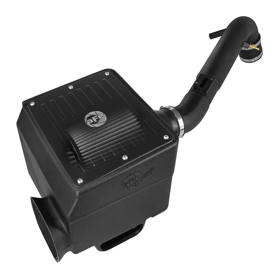
- Page 1 FLOW engineering Instruction Manual P/N: 51-82722 / 54-82722 Make: Toyota Model: Tacoma Year: 2005-2015 Engine: L4-2.7L...
- Page 2 • Please read the entire instruction manual before proceeding. • Ensure all components listed are present. • If you are missing any of the components, call customer support at 951-493-7100. • Ensure you have all necessary tools before proceeding. • Do not attempt to work on your vehicle when the engine is hot. •...
- Page 3 aFepower.com Page 3...
- Page 4 REMOVAL Figure A Refer to Figure A for Steps 1-3 Step 1: Remove the three bolts that secure the intake resonator to the valve cover 1 . Loosen the intake hose clamps 2 . Step 2: Remove the intake hose. Step 3: Remove MAF sensor 3 from OE airbox using phillips screwdriver.
- Page 5 REMOVAL Figure C Refer to Figure C for Steps 4-5 Step 4: Disconnect the breather hose 4 and the vacuum hose 5 connected to the fuel regulator, going to the intake resonator. Loosen the clamp on the throttle body. Step 5: Remove the VSV located 6 on the back side of the intake resonator and remove intake resonator.
- Page 6 REMOVAL Figure B Refer to Figure B for Steps 5-6 Step 5: Remove the three 12mm bolts securing the lower airbox. (Set two bolts aside for later use) Remove the lower airbox. Step 6: Remove 2 OE rubber grommets and spacers from lower airbox. (Set aside for later use) Page 6...
- Page 7 INSTALL Figure D Refer to Figure D for Steps 7-8 Step 7: Transfer MAF sensor to aFe intake tube with hardware provided using flathead screwdriver. Step 8: Install brass vacuum hose fitting onto aFe intake tube. aFepower.com Page 7...
- Page 8 INSTALL Figure E Refer to Figure E for Step 9 Step 9: Place the “L” bracket on the valve cover 7 . Secure with OE bolt from intake resonator. Secure the VSV with the supplied nuts and OE bolts. Page 8...
- Page 9 INSTALL Figure F Refer to Figure F for Step 10 Step 10: With OE rubber grommets removed form OE lower airbox, place onto new housing with metal spacers 8 . aFepower.com Page 9...
- Page 10 INSTALL Figure G Refer to Figure G for Step 11 Step 11: Insert M8 isolation mount 9 and hand tighten firmly. ( It may be necessary to clean the threads from undercoating or paint) Page 10...
- Page 11 INSTALL Figure H Refer to Figure H for Step 12 Step 12: Place intake adaptor into housing. Use the supplied M6 button head screws to attach adaptor and tighten 10 . Page 11...
- Page 12 INSTALL Figure I Refer to Figure I for Step 13 Step 13: Place housing into vehicle and tighten using two OE 12mm bolts from the lower airbox 11 . Using supplied M8 nut and washer tighten housing onto isolation mount with 13mm wrench 12 .
- Page 13 INSTALL Figure J Refer to Figure J for Steps 14-16 Step 14: Place coupler with clamp onto tube for adaptor side of housing. Then place coupler with clamp onto tube for throttle body side. Install loose to allow for repositioning. Step 15: Connect breather hose to intake tube 13.
- Page 14 INSTALL Figure K Refer to Figure K for Step 17 Step 17: Place high-flow filter into housing 15 and tighten using 8mm nut driver. Place cover on housing using M6 button head screws provided and tighten using 4mm allen wrench. Page 14...
- Page 15 INSTALL Figure J Refer to Figure J for Steps 18-19 Step 18: Check and adjust intake tube as needed and tighten all coupler clamps. Step 19: Your installation is now complete. Check to see if everything is connected and clamps are tight. Thank you for choosing aFe! Page 15...
- Page 16 Page left blank intentionally Page 16...
- Page 17 Page left blank intentionally Page 17...
- Page 18 Pro DRY S Air Filter Pro 5R Air Filter aFe Gear aFe Gear P/N: 21-91021 P/N: 24-91021 P/N: 40-10122 P/N: 40-10125 aFe Gear aFe Gear aFe Gear aFe Gear P/N: 40-10131 P/N: 40-30383 P/N: 40-10145 P/N: 40-10149 aFe Gear Air Intake System P/N: 40-31235 P/N: 54-11382 To purchase any of the items above, view airflow charts, dyno graphs, photos, and video;...
-
Page 19: Warranty
Warranty General Terms: • aFe warrants their products to be free from manufacturer’s defects due to workmanship and material. • This warranty applies only to the original purchaser of the product and is nontransferable. • Proof of purchase of the aFe product is required for all warranty claims. •... - Page 20 advanced FLOW engineering, inc. 252 Granite Street Corona, CA 92879 TEL: 951.493.7155 • TECH: 951.493.7100 E-Mail:Tech@aFepower.com P/N: 06-80710...
Need help?
Do you have a question about the 51-82722 and is the answer not in the manual?
Questions and answers