
Subscribe to Our Youtube Channel
Related Manuals for MKS 907 Series


Summary of Contents for MKS 907 Series
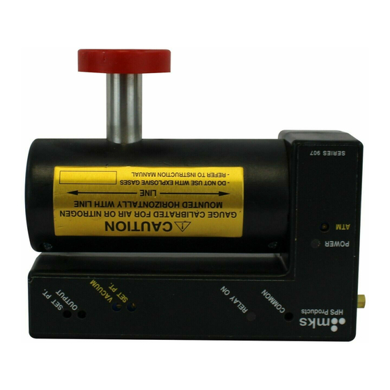
- Page 1 Series 907 Analog Convection Transducer Instruction Manual Instruction manual part number 109070001 Revision D - May 2020...
- Page 3 Phone: +1-833-986-1686 Email: insidesales@mksinst.com Visit our website at www.mksinst.com Instruction Manual © 2020 MKS Instruments, Inc. All rights reserved. mksinst is a trademark of MKS Instruments, Inc. All other trademarks and registered trademarks are the properties of their respective owners.
- Page 4 Series 907 Analog Convection Transducer (ACT) Catalog numbers for Series 907 Analog Convection Transducer Transducer Assembly Analog Convection Transducer, Single Set-Point, NW16, CE 109070010CE Analog Convection Transducer, Dual Set-Point, NW16, CE 109070019CE Analog Convection Transducer, Single Set-Point, NW25, CE 109070027CE...
-
Page 5: Table Of Contents
Table of Contents Chapter 1 General Information ............. . . 7 Receiving Inspection . - Page 6 Series 907 Analog Convection Transducer Instruction Manual - 109070001...
-
Page 7: Chapter 1 General Information
Any damaged material including all containers and packaging should be held for carrier inspection. Contact MKS Customer Support for assistance if your shipment is not correct for reasons other than shipping damage. -
Page 8: Customer Service / Technical Support
1 General Information 1.5 Customer Service / Technical Support Some minor problems are readily corrected on site. If the product requires service, contact the MKS Technical Support Department at +1-833-986-1686. If the product must be returned to the factory for service, request a Return Material Authorization (RMA) from MKS. Do not return products without first obtaining an RMA. -
Page 9: Safety
These instructions do not and cannot provide for every contingency that may arise in connection with the installation, operation, or maintenance of this product. If you require further assistance, contact MKS. This product was designed and tested to offer reasonably safe service provided it is installed, operated, and serviced in strict accordance with these safety instructions. -
Page 10: Responsibility
MKS literature including, but not limited to, manuals, instructions, bulletins, communications, and recommendations. For emergencies and for product safety related matters, contact the MKS Customer Service Department. See Section 1.5 or Section 6.2 for detailed information regarding how to contact MKS Customer Service Representatives. Series 907 Analog Convection Transducer... -
Page 11: Grounding Requirements
2 Safety 2.3 Grounding Requirements See Grounding, Section 4.2 in the Installation chapter for more detailed requirements regarding gauge and system grounding. Proper Grounding All components of a vacuum system used with this or any similar high voltage product must be maintained at Earth ground for safe operation. -
Page 12: High Voltage
2 Safety 2.4 High Voltage High Voltage is present in the unit when electrical power is applied to the electronics enclosure. Hazardous voltages may still be present for some time after disconnecting power to the electronics enclosure. Refer to the Installation and Service chapters for more information. High Voltage Be aware that when high voltage is present in any vacuum system, a life threatening electrical shock hazard may exist... -
Page 13: Over Pressure Conditions
2 Safety 2.5 Over Pressure Conditions Explosive Environment Do not use the Series 907 Transducer in an environment of explosive or combustible gases or gas mixtures. Operation of any electrical instrument in such an environment constitutes a definite safety hazard. Do not use the product to measure the pressure of explosive gases or gas mixtures. -
Page 14: Damage Requiring Service
Because of the danger of introducing additional hazards, do not install substitute parts or perform any unauthorized modification to the product. Return the product to a service facility designated by MKS for service and repair to ensure that safety features are maintained. Do not use this product if it has unauthorized modifications. -
Page 15: Chapter 3 Specifications
3Specifications 3.1 General Description The MKS Series 907 Analog Convection Transducer is a compact, modular, convection enhanced Pirani vacuum sensor/pressure switch with an integrated electronic control circuit. The 907 Transducer is designed for applications which require pressure control in the range of to 10 Torr. -
Page 16: Specifications
3 Specifications 3.4 Specifications Table 3-1 Specifications for the Series 907 Analog Convection Transducer Parameter Specification Performance Torr: 1.0 x 10 to 1.0 x 10 Measurement Range for N / Air mbar: 1.3 x 10 to 1.3 x 10 Do NOT use this product with flammable or explosive gases. -
Page 17: Chapter 4 Installation
4 Installation Chapter 4 4Installation 4.1 Transducer Location Notice Install the Transducer on the vacuum chamber where it is protected from physical damage and high heat. See Section 2.5, Over Pressure Conditions, for important safety information before mounting the gauge. Locate the 903 Transducer where it can measure process chamber or manifold pressure. -
Page 18: Electrical Connections
4 Installation Connect the Transducer to the vacuum system flange using the appropriate gasket and mounting hardware. Notice A solid electrical connection between the sensor tube and the grounded vacuum system must be used to shield the electronics from external power sources. - Page 19 4 Installation The power supply input may range from 12 to 30 Vdc. The positive side (+) of the power supply is connected to pin 3 and the minus side (-) is connected to pin 4 of the D-sub connector. Damage will occur if the polarity of the power supply input is reversed.
-
Page 20: Inductive Loads And Arc Suppression
4 Installation 4.3.2 Inductive Loads and Arc Suppression If the set point relay is used to switch inductive loads, e.g., solenoids, relays, transformers, etc., the arcing of the relay contacts might interfere with controller operation or reduce relay contact life. Therefore an arc suppression network is recommended. -
Page 21: Operation
5 Operation Chapter 5 1Operation 5.1 Introduction The Series 907 Analog Convection Transducer is designed for applications which require pressure control in the range of 10 to 10 Torr. Rapid response and wide measurement range provide the equipment designer with maximum flexibility. The 907 Transducer can operate autonomously or as part of a control system including that of a monitor or an alarm. -
Page 22: Typical Applications
5 Operation 5.2 Typical Applications • Measuring fore line and roughing pressures generated by mechanical vacuum pumps • Controlling valves and pumps to automate system pump down using the relay set point(s) • Sensing abnormal pressure and taking appropriate security measures using the relay set point(s) •... -
Page 23: Reading Pressure
5 Operation 5.4 Reading Pressure The 907 Transducer is calibrated for air/nitrogen and also indicates nitrogen equivalent pressure for argon and helium. See Figure 5-2 and Figure 5-3 for pressure readings based on output voltage from the transducer. See Section 5.6 when using the 907 Transducer with a computer to convert voltage to pressure readings. -
Page 24: Using The Series 907 Transducer With Other Gases
5.5 Using the Series 907 Transducer with Other Gases Before using the 907 Transducer to measure pressure of gases other than air or nitrogen, read and understand this section. Contact the MKS Customer Service Department if additional information is needed. -
Page 25: Nitrogen Equivalent Pressure And Voltage
5 Operation 5.5.1 Nitrogen Equivalent Pressure and Voltage The thermal loss from a heated sensor element is a function of the transporting gas. See Section 5.3, Theory of Operation. Since the 907 Transducer is such a sensor, the voltage output depends upon the gas measured. -
Page 26: Using The Series 907 Transducer With Computers
5 Operation 5.6 Using the Series 907 Transducer with Computers The 907 is designed to operate in highly automated systems, especially those that are controlled by digital computers. It is compatible with many different computers, interfaces, and software programs. Analog-to-Digital (A/D) Converter To take full advantage of the 907’s capabilities, an A/D converter should be used with an input voltage span of 0 to 6 V. -
Page 27: Chapter 6 Service & Maintenance
6 Service & Maintenance Chapter 6 2Service & Maintenance 6.1 Introduction The procedures in this section provide instructions for normal service issues that may be required during use of the Series 907 Analog Convection Transducer. 6.2 Service Guidelines Some minor difficulties are readily corrected in the field. Because the product contains static-sensitive electronic parts, the following precautions must be followed when troubleshooting: •... -
Page 28: Damage Requiring Service
Return the product to a service facility designated by MKS for service and repair to ensure that safety features are maintained. Do not use this product if it has unauthorized modifications. -
Page 29: Troubleshooting
1. Connect the power cable 2. Power supply turned OFF 2. Turn power ON 3. Defective PC board 3. Return to MKS for repair Analog output voltage 1. Analog output shorted to ground 1. Check the cable connections higher than 7 V 2. -
Page 30: Adjusting The Set Point
6 Service & Maintenance Figure 6-1: Transducer Calibration Points 6.6 Adjusting the Set Point Attach a digital voltmeter to the Common tip jack and either the Setpoint 1 or Setpoint 2 tip jack on the transducer. Adjust the corresponding potentiometer with a small screwdriver until the voltage reading coincides with the desired set point pressure shown in Figure 5-2. -
Page 31: Clean The Transducer Case And Sensor
6 Service & Maintenance Note the pressure reading. The pressure will either rise or fall, depending upon the thermal conductivity of the probe gas relative to the system gas. The largest change in value indicates the probe gas is nearest the leak location. Repeat the test to confirm. -
Page 32: Replace The Sensor Tube
6 Service & Maintenance 6.10 Replace the Sensor Tube Disconnect the power cable from the 907 Transducer assembly. Remove the two screws with a #1 Phillips head screwdriver. Use a 3/16-inch nut driver to remove only the right screw lock from the D- sub connector. Carefully remove the front cover of the transducer case. -
Page 33: Reassemble The Electronics Subassembly
6 Service & Maintenance Adjust potentiometer R38 to a voltmeter reading of 5.487 V. Calibrate the sensor for vacuum and atmosphere following the steps on page 14. Disconnect the power cable. 6.10.2 Reassemble the Electronics Subassembly Carefully replace the front cover of the case. Secure the remaining sensor tube screw and the screw lock. -
Page 34: Accessories/ Spare Parts
6 Service & Maintenance 6.12 Accessories/ Spare Parts Table 6-3 907 Spare Parts List Item Part # Transducer w 1 Setpoint KF16 109070010CE KF25 109070027CE 1/8” NPT-M w 1/2” compression Seal 109070011CE ® 8 VCR -F (½") 109070012CE 1-1/3” CF 109070013CE 2-3/4”... -
Page 35: Index
Index 9, 10 Caution Notices & Symbols Over Pressure Conditions Damage requiring service Receiving Inspection Grounding Safety 9, 10 Gauge to Vacuum Chamber Cautions & Warnings Requirements Service Guidelines Service guidelines High Voltage Specifications Storage Introduction General Description 9, 10 Warning Notices &... - Page 36 Series 907 Analog Convection Transducer Instruction Manual - #109070001...
- Page 38 Series 907 Analog Convection Transducer Customer Service / Technical Support: MKS Global Headquarters 2 Tech Drive, Suite 201 Andover MA, 01810 USA Phone: +1-833-986-1686 Email: insidesales@mksinst.com Visit our website at www.mksinst.com Instruction Manual Instruction manual part number 109070001 Revision D - May 2020...
Need help?
Do you have a question about the 907 Series and is the answer not in the manual?
Questions and answers