Table of Contents
Advertisement
Advertisement
Table of Contents

Related Manuals for MKS 910 DualTrans Series


Summary of Contents for MKS 910 DualTrans Series
- Page 1 Series 910 DualTrans Transducer Operation and Maintenance Manual...
- Page 3 Series 910 DualTrans Transducer January, 2003 Part # 100013085 Series 910 DualTrans...
- Page 4 1- 303-449-9861 1-800-345-1967 Fax: 1-303-442-6880 Web: www.mksinst.com/hpshome.html For technical support, contact: ® Products of MKS Instruments, Inc., Denmark Office Nordre Strandvej 119 G, 3150 Hellebaek Denmark Phone: +45 44929299 Fax: +45 44929499 ® ©2002 by HPS Products of MKS Instruments, Inc.
-
Page 5: Table Of Contents
Table of Contents Package Contents ..............7 Symbols Used in this Manual ............ 8 Safety Precautions ..............9 General Specifications ............10 Feature and Control Locations ..........11 About the 910 DualTrans ....................Typical Applications for the 910 DualTrans ..........Installing the 910 DualTrans .................. - Page 6 Model – MD ..................23 Pressure Reading – PR1, PR2 ............23 Serial Number – SN ................. 24 Time On – TIM ................. 24 Transducer Temperature – TEM ............24 Set Point Commands ................25 Set Point Value – SP1, SP2, SP3 ............ 25 Hysteresis Value –...
-
Page 7: Package Contents
If any items are missing from the package, call MKS Customer Service at 1-303-449-9861 or 1-800-345-1967. Do not return the product to MKS unless specified to do so by MKS Customer Service. MKS customer service and support: MKS Instruments, Inc. -
Page 8: Symbols Used In This Manual
Symbols Used in this Manual CAUTION: Refer to the manual. Failure to heed the message could result in personal injury, serious damage to the equipment, or both. Calls attention to important procedures, practices, or conditions. Series 910 DualTrans... -
Page 9: Safety Precautions
Do not substitute parts or modify instrument. Do not install substitute parts or perform any unauthorized modification to the instrument. Return the instrument to an MKS Calibration and Service Center for service and repair to ensure that all of the safety features are maintained. -
Page 10: General Specifications
General Specifications Measuring range Pirani(PR1) 1x10 to 900 Torr Measuring range Piezo(PR2) 0.1 to 1500 Torr Measuring Range 1x10 to 1500 Torr Combination(PR3) Accuracy Combination(PR3) 1%: Range 10 to 1000 Torr 10%: Range 10 to 10 Torr Repeatability of 1%: Range 10 to 1000 Torr Combination (PR3) 5%: Range 10... -
Page 11: Feature And Control Locations
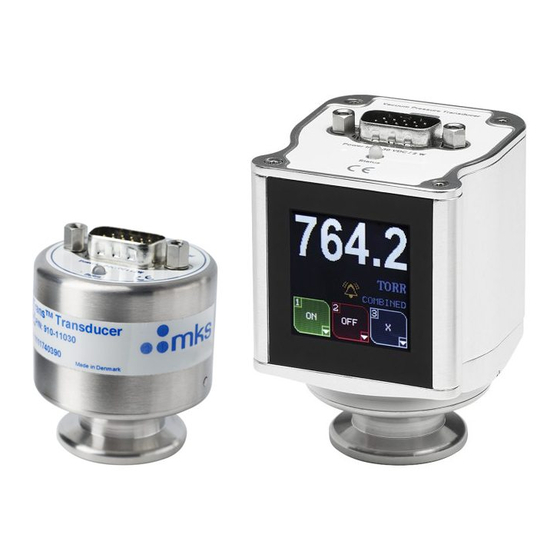
Feature and Control Locations User access is through the 15-pin D-sub connector. The ZERO adjust button allows the user to manually perform zero calibration. See Calibration Commands in the RS-485 Command Set section for more information. The figures below show the front and top view of the 910. FRONT VIEW MALE, 15-PIN D-SUB CONNECTOR HPS Products... -
Page 12: About The 910 Dualtrans
About the 910 DualTrans The 910 DualTrans is designed specifically for the semiconductor OEM environment. It combines an absolute Piezo sensor as an acccurate atmospheric pressure sensor and a MicroPirani sensor to measure vacuum pressure with integrated electronic control circuits. Once integrated into the vacuum system, the 910 DualTrans functions are computer-controlled, requiring little manual intervention by the user. -
Page 13: Typical Applications For The 910 Dualtrans
Typical Applications for the 910 DualTrans ♦ Semiconductor applications. ♦ Measure foreline and roughing pressures generated by mechanical vacuum pumps. ♦ Control valves and pumps to automate pump-down using relay set points. ♦ Sense abnormal pressure and take appropriate security measures using relay set points. -
Page 14: Installing The 910 Dualtrans
Installing the 910 DualTrans Transducer Installation Location Locate the DualTrans where it can measure chamber or manifold pressure. Install it away from pumps and gas sources and where vibration is minimal to give the most representative pressure measurement. Orientation The 910 DualTrans can be mounted in any orientation. -
Page 15: Electrical Connection
1.60 [40.64] HPS Products Series 910 3.62 DualTrans [91.95] Transducer Zero Made In Denmark www.mksinst.com ® 4 VCR F FLANGE 3.92" (99.57) ® 8 VCR F NW 16KF 4.53" (115.01) NW 25KF 4.86" (123.55) 1-1/3" CF 4.90" (124.41) 2-3/4" CF 5.14"... -
Page 16: 910 Dualtrans Tm Electrical Connections Table
The power supply input is 9 to 30 VDC. The positive side of the power supply is connected to pin 3 and the negative side to pin 4 of the male D-sub connector. The power supply input is protected by an internal fuse. The fuse is self-recoverable;... -
Page 17: Relay Inductive Loads And Arc Suppression
Relay Inductive Loads and Arc Suppression If using the set point relay to switch inductive loads (e.g., solenoids, relays, transformers, etc.), the arcing of the relay contacts might interfere with 910 operation and reduce relay contact life. Therefore, an arc suppression network, shown schematically below, is recommended. -
Page 18: Operation
Operation The 910 DualTrans operation parameters are preset at the factory. The table below shows the factory default settings. Use the user interface and the commands described on the following pages to change parameter settings as necessary. The user interface to the 910 DualTrans is through either RS-232 or RS-485 serial communications. -
Page 19: Rs-485 Protocol
RS-485 Protocol The 910 supports 2400, 4800, 9600, and 19200 baud rates (factory default: 9600). The data format is 8 data bits, no parity, and one stop bit. Standard Addresses Valid addresses are 3 digits, 001 to 253 (factory default: 253). Universal Addresses The 910 receives and responds to commands sent to address 254. -
Page 20: Response Syntax (Ack/Nak)
Response Syntax (ACK/NAK) The ASCII characters 'ACK' or 'NAK' preface the query or command response string. The ACK sequence signifies the message was processed successfully. The NAK sequence indicates there was an error. The response to a query or a successful command is: @<device address>ACK<data>;FF The response to a message with an error is: @<device address>NAK;FF... -
Page 21: Rs-485 Command Set
RS-485 Command Set The query and command formats shown in this section are examples; the values may vary for the user’s installation. Set Up Commands Address – AD The AD command returns or sets the 910 address. Note: If multiple devices are installed on the system, an address query using 254 (shown in the query example below) cannot determine the address of only one of the devices. -
Page 22: Rs Delay - Rsd
RS Delay – RSD The RSD command enables or disables a delay of up to 5milliseconds between recieve and transmit mode. The delay is required in some half duplex applications like RS232 to RS485 converters. Values: OFF, ON (default OFF) Query: @001RSD?;FF Query Response:... -
Page 23: Status Commands
Status Commands Device Type – DT The DT command returns the transducer device type. Query: @001DT?;FF Query Response: @001ACKDUALTRANS;FF Firmware Version – FV The FV command returns the 910 firmware version. Query: @001FV?;FF Query Response: @001ACK1.00;FF Hardware Version – HV The HV command returns the 910 hardware version. -
Page 24: Serial Number - Sn
Pressure Reading PR-4 The PR4 is a high resolution combined reading as the PR3. Pressure Reading PR5 PR5 measures the differential value between PR1 MicroPirani reading and PR2 Piezo reading. This command can be used for leak detection. Serial Number – SN The SN command returns the 910 serial number. -
Page 25: Set Point Commands
Set Point Commands The 910 has three independent set point relays for control. The relays can be enabled or disabled with the Enable Set Point – EN1, EN2, EN3 command (next page). Set Point Value – SP1, SP2, SP3 The set point value command returns or sets the set point value. The set point value is the pressure either below or above which the set point relay will be energized (i.e., N.O. -
Page 26: Set Point Direction - Sd1, Sd2, Sd3
Set Point Direction – SD1, SD2, SD3 The set point direction command returns or sets the direction of the set point. BELOW sets the relay when the pressure is below the set point value; ABOVE sets the relay when the pressure is above the set point value. Whenever the SD command is implemented the setpoint hysteresis is automatically set to +10% of set point value if set point direction command is below and -10% of set point value is if set point direction command is above. -
Page 27: Enable Set Point - En1, En2, En3
Enable Set Point – EN1, EN2, EN3 The enable set point command returns enable status or disables the set point relay. The setpoint are always associated with the combination output (PR3). Values: ON,OFF (default: OFF) Query: @001EN1?;FF Query Response: @001ACKOFF;FF Command: @001EN1!ON;FF Command:... -
Page 28: Calibration Commands
Calibration Commands Span Calibration – SPN The SPN command sets full scale span for the Piezo. Enter the applied full scale calibration pressure in the range from 100 to 1000 Torr. Values: Pressure value in scientific notation Command: @001SPN!1.00E+2;FF Command Response: @001ACK1.00E+2;FF Zero Calibration –... -
Page 29: Gas Type Calibration - Gt
Gas Type Calibration – GT The GT command sets gas type for measurement. The MicroPirani measures thermal conductivity; using the gas calibration compensates for gas errors. Values: NITROGEN, AIR, ARGON, HYDROGEN, HELIUM, 0 (default: NITROGEN) Query: @001GT?;FF Query Response: @001ACKAIR;FF Command: @001GT!NITROGEN;FF Command Response:... -
Page 30: Analog Output
Analog Output The analog output voltage is derived from the combnation output (PR3). The analog voltage signals are pins 5 (+) and 6 (-). Connect them to a differential input. The transducer provides a analog output of 1 VDC per decade. The minimum output voltage is 1 VDC at 1 x 10 Torr. - Page 31 Pressure to Voltage Table Pressure (Torr) Volts Pressure (Torr) Volts 1.0x10 1.0x10 1.00 5.00 2.0x10 1.30 2.0x10 5.30 4.0x10 4.0x10 1.60 5.60 6.0x10 1.77 6.0x10 5.77 8.0x10 8.0x10 1.90 5.90 1.0x10 2.00 1.0x10 6.00 2.0x10 2.30 2.0x10 6.30 4.0x10 4.0x10 2.60 6.60 6.0x10...
-
Page 32: Manual Procedures For The 910 Dualtrans
Manual Procedures for the 910 DualTrans Calibrating for Zero Though factory calibrated, the DualTrans ’s calibration may change due to reasons such as filament contamination or aging of the electronic components. If necessary, the user can adjust zero calibration of the DualTrans The user can adjust zero calibration by using the Vacuum Calibration –... - Page 33 Probe the suspected leak areas with a gas that has a molecular weight different that of the system gas. Helium is suitable for probing a system pumping air or nitrogen. 1. Pump system to pressure not lower than 1 Torr. 2.
-
Page 34: Maintenance And Troubleshooting
Maintenance and Troubleshooting Maintenance and Troubleshooting Table – – Series 910 DualTrans... -
Page 35: Cleaning The 910 Dualtrans
Cleaning the 910 DualTrans Case and Sensor Tube The finish of the 910 DualTrans case is designed to resist many laboratory solvents; clean the case with water or alcohol. Take care to prevent a liquid from entering the electronic enclosure. Roughing pump oils and other fluids condensing or decomposing on the heated filament can contaminate the sensor elements. -
Page 36: Accessories And Part Replacement
Accessories and Part Replacement Description Part Number Transducer with NW16 KF flange, RS-232 comm. 910-11 Transducer with NW16 KF flange, RS-485 comm. 910-12 ® Transducer with 4VCR F flange, RS-232 comm. 910-41 ® Transducer with 4VCR F flange, RS-485 comm. 910-42 ®... - Page 37 Notes: Series 910 DualTrans...
-
Page 38: Warranty
MKS or authorized representative to the original purchase (PURCHASER). Any product or parts of the product repaired or replaced by MKS under this warranty are warranted only for the remaining unexpired part of its one (1) year original warranty period. After expiration of the applicable warranty period, the PURCHASER shall be charged MKS’... -
Page 39: Appendix: How The 910 Dualtrans
Appendix: How the 910 DualTrans Works The Series 910 DualTrans Transducer is a combination of two different types of pressure sensors: the MicroPirani and the Piezo. The MicroPirani sensor measures pressure indirectly as a heat-loss manometer that infers the pressure of a gas by measuring thermal loss from a heated wire. The Piezo measures pressure directly as a force or pressure is applied to a diaphragm with a piezoresistive Wheatstone bridge network. -
Page 40: Micropirani
MicroPirani The MicroPirani sensor functions the same as a traditional Pirani sensor, but instead of a heated wire, a thin film Nickel resistive element is deposited onto a silicon substrate. This heated filament is maintained at a constant temperature above the ambient temperature of the substrate. A solid-state MicroPirani sensor has several advantages over a wire based Pirani sensor. -
Page 41: Piezo
Piezo The Piezo sensor consists of a bridge of piezoresistive elements on a diaphragm, which change their resistance proportional to the pressure applied to the sensor. The resistance change in a monocrystalline semiconductor (piezoelectric effect) is substantially higher than that in a standard strain gauge. - Page 42 Series 910 DualTrans...
Need help?
Do you have a question about the 910 DualTrans Series and is the answer not in the manual?
Questions and answers