
Related Manuals for MKS 905 MicroPirani


Summary of Contents for MKS 905 MicroPirani
- Page 1 905 MicroPirani Sensor Kit RS232 / RS485 Design Guide P/N: 100013905 Revision: A, September, 2007...
- Page 2 Extent of the Warranty MKS Instruments, Inc., HPS™ Products Inc. and MKS Denmark ApS warrants the 905-00XX MicroPirani™ Sensor Kit and its accessories to be free from defects in materials and workmanship for one (1) year from the date of shipment by HPS™ or authorized representative to the original purchaser (PURCHASER).
-
Page 3: Table Of Contents
Connections .............................. 8 D-SUB male connector pinout ........................8 Specifications ............................8 Getting started with the 905 MicroPirani™ Sensor Kit ..................9 Installing the electronics module....................... 9 Connecting the electronics module with the sensor ................. 9 Choosing communication standard ......................9 Connecting the communication cable....................... - Page 4 MKS Denmark ApS Ndr. Strandvej 119G DK-3150 Hellebæk Denmark Tel: +45 44 92 92 99 – Fax: +45 44 92 94 99 Email: mksdenmark@mksinst.com MKS Instruments, HPS Products 5330 Sterling Dr. CO-80301 Boulder Tel: 303 449 9861 - Fax: 303 449 2003...
-
Page 5: Symbols Used In This Manual
Symbols used in this manual Failure to read message could result in damage to the equipment Calls attention to important procedures, practices or conditions. Series 905 Page 1 Design Guide... -
Page 6: Package Contents
Package contents Before unpacking the 905 MicroPirani™ Sensor Kit, check all surfaces of the packaging material for shipping damage. Please make sure that your package contains the following items with respect to the last four digits of the part number:... -
Page 7: About The 905 Micropirani™ Sensor Kit
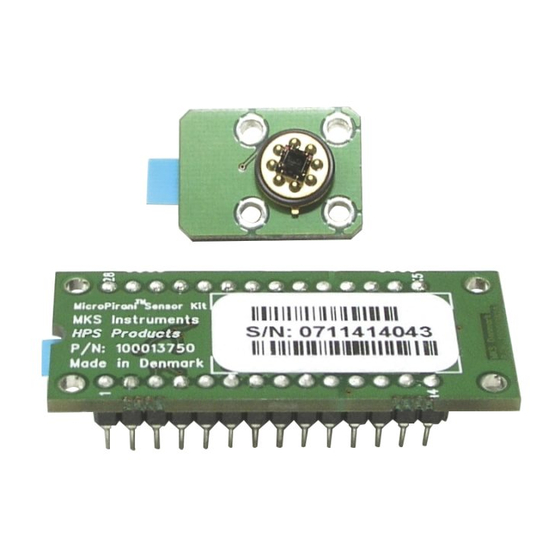
• Standard DIP 28 pin footprint for easy integration • RoHS compliant The 905 MicroPirani™ Sensor Kit is a calibrated plug and play vacuum pressure transducer solution for OEM system integration. The kit consists of a MEMS-based pressure sensor and a measuring electronics and processor module. - Page 8 The following are some of the more common applications for the MicroPirani™ Sensor Kit: Gas leak detection The portable MKS Pico helium leak detector uses MicroPirani™ sensor kit technology for inlet vacuum measurement and protection of the helium mass spectrometer.
-
Page 9: 905 Micropirani™ Sensor Kit Specifications
905 MicroPirani™ Sensor Kit specifications Measurement range 1 × 10 to 760 Torr 1 × 10 to 1000 mbar 1 × 10 to 1 ×10 Pascal Measurement accuracy Pressure units (user selectable) Torr, mbar, Pascal Supply voltage +5VDC (±2%) Supply current... -
Page 10: Electronics Module Dimensions
Electronics module dimensions Figure 4 - Dimensions: millimeters [inches] MicroPirani™ sensor and board dimensions Figure 5 - Dimensions: millimeters [inches] Series 905 Page 6 Design Guide... -
Page 11: About The Evaluation Board
About the evaluation board The MicroPirani™ Sensor Kit is designed for a high level of integration, but the evaluation board can get the MicroPirani™ sensor kit up and running in minutes. The evaluation board offers both RS232 and RS485 digital communication and can be connected directly to a PC for real time pressure data logging and setup of digital parameters. -
Page 12: Evaluation Board Overview
Evaluation board overview Connections The following symbols refer to the picture: Symbol: Description: V+ / Gnd Optional power supply connection. Vsupply Choose supply voltage from the DSUB connector or screw terminals (Vext). Activity LED Indicates current system status. Zero Switch Used to zero the pressure readout at vacuum Reset Short circuit and release to reset the microcontroller... -
Page 13: Getting Started With The 905 Micropirani™ Sensor Kit
Getting started with the 905 MicroPirani™ Sensor Kit This guide describes how to install and operate the MicroPirani™ Sensor Kit with the evaluation board. For a complete description of how to integrate the 905 in a system see the next chapters. -
Page 14: Powering Up The System
Powering up the system Make sure, that the Vsupply jumper is set to ’DSUB’: PDR900: Power on the PDR900 and wait a few seconds. The MicroPirani™ Sensor Kit will present itself as a 905 transducer on the PDR900 display. Refer to the PDR900 manual for configuration and operating instructions. -
Page 15: Integrating The 905 Micropirani™ Sensor Kit
Integrating the 905 MicroPirani™ Sensor Kit This chapter deals with the integration of the 905. Every aspect of the integration is covered, such as how to connect the sensor and how to choose the external components needed to make the 905 operate at peak performance. -
Page 16: Micropirani™ Electrical Connections
The flexible flat cable fits directly in the connector on the electronics module and provides a firm connection of the MicroPirani™ sensor. Use the cable provided by MKS or a 10 pin FFC cable with 0.5mm pitch and gold plated contacts. See the specifications for the P/N of the connector the cable should be made to fit in. -
Page 17: Regular Cable
Regular cable A regular round cable can be used if the DIP socket connections have been chosen, but the printed circuit board (where the electronics module is mounted) does not extend all the way to the sensor. Use a shielded cable if possible and optimise for minimal length to minimise measuring noise. -
Page 18: Communication
Communication The electronics module sends and receives TTL level signals direcly from the microcontroller. How these signals should be integrated with the rest of the setup depends on the user configuration and application. If the 905 is to communicate directly with another microcontroller no signal conversion is necessary and TxD/RxD (pins 20 and 21 respectively) can be connected directly. -
Page 19: Analog Output
Analog Output The analog voltage output can be used for connection to external analog measuring equipment for pressure reading and data logging. The analog output must be connected to a true differential input voltmeter or an analog to digital (A/D) converter with a differential input in a system controller. The analog output will change scale when the pressure unit is changed and will always provide 0.5VDC per decade whether Torr, mbar or Pascal is selected. -
Page 20: Pressure To Voltage Table
Pressure to voltage table Pressure Output Pressure Output [Torr/mbar]: [Torr/mbar] 1.0 × 10 0.500V 1.0 × 10 2.500V 2.0 × 10 0.651V 2.0 × 10 2.651V 4.0 × 10 0.801V 4.0 × 10 2.801V 6.0 × 10 0.889V 6.0 × 10 2.889V 8.0 ×... -
Page 21: Ground To Earth Connection
Ground to earth connection When installing the electronics module in a system the grounding scheme must be carefully chosen, otherwise measuring errors can occur. We strongly suggest that the MicroPirani™ Sensor Kit ground (found on pin 15) is connected to earth in one location only, which, as an example, could be at an external connection such as a DSUB connector. -
Page 22: Activity Led
Set point outputs The 905 MicroPirani™ Sensor Kit has three independent set point outputs located on pins 12,13 and 14 on the electronics module. A relay (three in all) connect between the output (respectively 1, 2 and 3 on the evaluation board) and a 5V connection. -
Page 23: Updating The Firmware
Under normal circumstances the firmware does not need upgrading, but it enables upgrading units if custom features have been implemented or a issue has been fixed. Figure 22 - The MKS firmware downloader As can be seen above the firmware downloader user interface is simple. -
Page 24: Manual Procedures For The 905
Manual procedures for the 905 Adjustment for Zero Though factory calibrated, the MicroPirani™ Sensor Kit calibration may change due to reasons such as filament contamination or aging of the electronic components. If necessary, the user can adjust zero calibration of the MicroPirani™ Sensor Kit. The user can adjust zero calibration by using the Vacuum Calibration –... -
Page 25: Operation
Operation The MicroPirani™ Sensor Kit operation parameters are preset at the factory. The table below shows the factory default settings. The user interface and the commands described on the following pages can be used to change parameter settings as necessary. The user interface to the MicroPirani™ Sensor Kit is through either TTL, RS232 or RS485 serial communication (all available on the evaluation board). -
Page 26: Rs-485 Protocol
RS-485 Protocol The 905 supports 2400, 4800, 9600, 19200, 38400 and 115200 baud rates (factory default: 9600). The data format is 8 data bits, no parity, and one stop bit. Standard Addresses Valid addresses are 3 digits, 001 to 253 (factory default: 253). Universal Addresses The 905 receives and responds to commands sent to address 254. -
Page 27: Rs232 / Rs485 Command Set
RS232 / RS485 Command Set The query and command formats shown in this section are examples; the values may vary for the user’s installation. Set Up Commands Address – AD The AD command returns or sets the 905 address. Note: If multiple devices are installed on the system, an address query using 254 (shown in the query example below) can only determine the address of one of the devices. -
Page 28: Rs Delay - Rsd
RS Delay – RSD The RSD command enables or disables a delay of up to 5 milliseconds between receive and transmit mode. Some RS485 to RS232 converters requires this delay in order to operate. Values: (default Query: @253RSD?;FF Query Response: @253ACKOFF;FF Command: @253RSD!ON;FF... -
Page 29: Status Commands
Status Commands Device Type – DT The DT command returns the transducer device type. Query: @253DT?;FF Query Response: @253ACKMICROPIRANI;FF Firmware Version – FV The FV command returns the 905 firmware version. Query: @253FV?;FF Query Response: @253ACK1.00;FF Hardware Version – HV The HV command returns the 905 hardware version. -
Page 30: Time On - Tim
Time On – TIM The TIM command returns the number of hours the 905 has been on. Query: @253TIM?;FF Query Response: @253ACK000000001;FF Transducer Temperature – TEM The TEM command returns the MicroPiranis on-chip sensor temperature in Query: @253TEM?;FF Query Response: @253ACK2.10E+1;FF Set Point Commands The 905 has three independent set points which can be used for process control or surveillance. -
Page 31: Set Value - Sp1,Sp2,Sp3
Set Value – SP1,SP2,SP3 The set point value command returns or sets the set point value. The set point value is the pressure either below or above which the set point will be activated. The direction of the set point (ABOVE or BELOW) is configured using the Set Point Direction –... -
Page 32: Set Point Direction - Sd1, Sd2, Sd3
Set Point Direction – SD1, SD2, SD3 The set point direction command returns or sets the direction of the set point. BELOW activates the set point when the pressure is below the set point value; ABOVE activates the set point when the pressure is above the set point value. -
Page 33: Calibration And Adjustment Commands
Calibration and Adjustment Commands Atmospheric Calibration – ATM The ATM command sets full scale readout for the MicroPirani™. Vent the transducer to atmospheric pressure before performing atmospheric calibration. Optionally, the user can manually vent to atmosphere, as described in the section Venting to Atmosphere. Values: Pressure value in scientific notation Command: @253ATM!7.60E+2;FF... -
Page 34: How The Micropirani™ Sensor Works
How the MicroPirani™ Sensor Works The Pirani principle, first described in 1906 by Marcello S. Pirani, has been widely adopted for pressure measurements in the medium vacuum range. Its advantages are the rather simple sensor element and the broad measuring range. A traditional Pirani sensor typically consists of a thin tungsten wire which is suspended along the axis of a surrounding tube. -
Page 35: Ordering Information
Ordering information 905 MicroPirani™ Sensor Kits Part Number Description 905-0001 905 Evaluation Board, KF16 Flange (without Power Supply) 905-0002 905 Evaluation Board, KF16 Flange (with Power Supply) 905-0003 905 Electronics Module, Nude Sensor 905-0004 905 Electronics Module, Sensor Board, 200mm Flexible Flat Cable... - Page 36 P/N: 100013905 Revision: A, September, 2007...
Need help?
Do you have a question about the 905 MicroPirani and is the answer not in the manual?
Questions and answers