
Related Manuals for MKS UniMag 971


Summary of Contents for MKS UniMag 971
- Page 1 ™ P/N: 100017131 971 UniMag™ Transducer Operation and Installation Manual Revision: C, January, 2010...
- Page 2 Extent of the Warranty MKS Instruments, Inc., HPS™ Products Inc. and MKS Denmark ApS. warrants the 971 UniMag Vacuum Transducer and its accessories to be free from defects in materials and workmanship for one (1) year from the date of shipment by HPS™ or authorized representative to the original purchaser (PURCHASER).
-
Page 3: Table Of Contents
Safety information .............................. 2 Symbols used: ............................... 2 Unpacking ................................3 Description ................................. 4 971 Functions ..............................5 User Switch ................................ 5 LED Status Indicator ............................5 Transducer installation (mechanical) ......................... 6 Transducer installation (electrical) ........................7 Serial user interface ............................9 Communication Protocol.......................... - Page 4 MKS Denmark ApS. Ndr. Strandvej 119G DK-3150 Hellebaek Denmark Tel: +45 44 92 92 99 – Fax: +45 44 92 94 99 E-mail: mksdenmark@mksinst.com MKS Instruments, HPS Products 5330 Sterling Dr. Boulder, CO 80301 Tel: 303 449 9861 Fax: 303 449 2003...
-
Page 5: Safety Information
Service and Repair page 31. Do not install substituted parts or perform any unauthorized modification to the instrument. Return the instrument to a MKS Calibration and Service Center for service and repair to ensure all of the safety features are maintained. -
Page 6: Unpacking
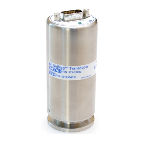
100017096 Documentation & Software CD If any items are missing, please call MKS Customer Service at (800)345-1967 or (303)449-9861 or your local MKS sales office or distributor. The 971 UniMag part number system has 5 digits that identify flange, communication interface, analog output type, I/O connector and sensor sealing type. - Page 7 The 971 UniMag™ vacuum transducer offers a wide measuring range from 1×10 to 5×10 Torr and is based on measurement of cold cathode ionization current. The 971 is designed for general purpose pressure measurement and control as a standalone unit or with the PDR900 display and controller unit.
- Page 8 User Switch I/O Connector Red or Green LED Status Indicator The user switch turns on cold cathode sensor. Refer to pages 15 for operation procedure. The cold cathode sensor should only be turned on when vacuum pressure is below 5×10 Torr ...
- Page 9 Do not use or install the 971 transducer where the following conditions occur: - Temperatures lower than 0 C or higher than 40 - Corrosive or explosive gases - Direct sunlight or other heat sources - Magnetic fields Process compatibility The 971 transducer is intended for use in relatively clean environments.
- Page 10 The 971 is available with different input/output connectors. Use a cable with strain relief to ensure proper electrical connection and to reduce stress on the connectors. Ensure a low impedance electrical connection between the 971 transducer body and the grounded vacuum system to shield the sensor from external electromagnetic sources.
-
Page 11: Description
Input/Output Wiring 971 I/O Connector (15 pin) PIN Description RS485- / RS232 Transmit RS485+ / RS232 Receive Power + (9-30 VDC) Power return - Analog Output + Analog Output - Relay 1, Normally Open Relay 1, Common Relay 1, Normally Closed 15 pin male HD DSUB Relay 2, Normally Closed Relay 2, Common... - Page 12 The 971 is as standard supplied with RS232 or RS485 user interface. The user interface allows change of transducer parameters such as set point settings and calibration. The serial interface uses the following data format: 8 data bits, 1 stop bit and no parity bit. RS232 user interface The 971 is DCE (Data Communication Equipment) and can be connected to DTE (Data Terminal Equipment), typically a...
- Page 13 To the right is illustrated the Windows communication port properties for communicating with transducer factory default settings. MKS also offers communication software examples that can be downloaded at: www.mksinst.com/vtsw/ In OEM applications transducer communication software routines are normally integrated with other system control software.
- Page 14 The transducer will reply in the current baud rate and then change to the new value. Addressing The transducer uses an addressable communication protocol that allows multiple MKS 900 Series transducer devices to be connected in a RS485 network. The address is required in both RS232 and RS485 communication.
-
Page 15: Functions
The 971 can be ordered with 3 mechanical relays that can be used for controlling external process equipment. The relay has closing and breaking contacts and the contacts are rated 30 VDC, 1A resistive load. If the transducer is supplied without setpoint relays, the setpoint commands can still be accessed. Refer to part number definition page 3 to verify if setpoint relays are included. - Page 16 When using the setpoint relay to control process equipment, always take appropriate precautions to prevent system damage in case of transducer power failure. The NC contact will be closed in case of transducer power failure. If the transducer is supplied as a special version (P/N: 971-xxxxx-xxxx) with pre-configured parameters such as setpoint settings, the setup is per default locked.
- Page 17 The setpoint safety delay function requires 5 continuously measurements that exceeds setpoint value before the relay is tripped. This feature prevents that noise or pressure pulse can trig the relay. If fast setpoint response is required the setpoint safety delay can be disabled. Setpoint safety delay Command: @253SPD!ON;FF...
-
Page 18: User Switch
The cold cathode sensor must be turned on before the transducer can provide pressure measurement values. The 971 can be controlled via digital interface, external analog control or manually. P/N: 971-x1090-0001, will always enable the high voltage when power is turned on. Power supply must be external controlled by switching power (pin 4) on and off to avoid continuously operation at high pressure. - Page 19 The 971 transducer can provide pressure measurement output as an analog voltage or RS232/RS485 digital value. The digital value is 3 digits scientific notation for PR1, PR3, PR5 reading and 4 digits for PR4 reading. Pressure request: Query: @253PR1?;FF Query reply: @253ACK1.23E-4;FF Pressure outputs: PR1:...
- Page 20 Cold Cathode protect setpoint The Cold Cathode protect setpoint automatically turns off the Cold Cathode high voltage if the cold cathode measurement exceeds 5.00E-3 Torr for 120 seconds. The protect setpoint can be turned off (disabled) or time set between 0 and 999 seconds. Command: @253PRO!ON;FF Command values:...
- Page 21 Switch enable: × Analog out 1: AO1! × (1) If the transducer is delivered with other analog output than standard mks (part number specified), then the factory default value will be specified by the specials part number. Calibration setup: Description Command...
- Page 22 This option is defined in the special settings. If delivered with factory lock the transducer settings can only by changed by return of gauge to MKS. The User Switch command defines if the Cold Cathode sensor voltage is turned on by level trig or pulse trig.
- Page 23 Device Type - DT Specifies transducer device type name: Query: @253DT?;FF Query reply: @253ACKUNIMAG;FF Firmware Version - FV Specifies transducer firmware version: Query: @253FV?;FF Query reply: @253ACK1.12;FF Hardware Version - HV Specifies transducer hardware version: Query: @253HV?;FF Query reply: @253ACKA;FF Manufacturer - MF Specifies transducer manufacturer: Query:...
- Page 24 ((2×Vout - 6) Pascal The standard MKS analog output always provides 0.5 VDC/decade. If the transducer pressure unit is changed from Torr to Pascal or mbar the analog output scaling will change as well, so it represents 0.5 VDC/decade Torr or 0.5 VDC/decade mbar or Pascal.
- Page 25 9 = MKS Moducell 325 (x3) 10 = MKS Baratron 0.1 Torr (0-10 VDC) 11 = MKS Baratron 1 Torr (0-10 VDC) / Hasting 2002OBE, Channel 2 12 = MKS Baratron 10 Torr (0-10 VDC) 13 = MKS Baratron 100 Torr (0-10 VDC)
- Page 26 Analog output calibration = 3 (Edward WRG emulation) The WRG emulation covers a wider measuring range than supported by the 971 range. (1.5× Vout -12.125) = 10 = (log )+12.125) / 1.5 Torr Torr (1.5× Vout -12) = 10 = (log )+12) / 1.5 mbar mbar...
- Page 27 Analog output calibration = 6 (Inficon BPG400 emulation) ((Vout -7.75)/0.75)-0.125 = 10 = log +0.125) × 0.75 + 7.75 Torr Torr (Vout -7.75)/0.75) = 10 = log ) × 0.75 mbar mbar (Vout -7.75)/0.75)+2 = 10 = log – 2) × 0.75 Pascal Pascal Torr...
- Page 28 Analog out calibration = 17 (Edwards AIM-X /-XL) The Edwards AIM-X / XL emulation provides a log linear output. Torr mbar Pascal Vout 1.00E-8 1.33E-8 1.33E-6 3.286 5.00E-8 6.67E-8 6.67E-6 4.084 1.00E-7 1.33E-7 1.33E-5 4.428 5.00E-7 6.67E-7 6.67E-5 5.227 1.00E-6 1.33E-6 1.33E-4 5.571...
- Page 29 Transducer information Command Response Explanation @xxxMD?;FF @xxxACK971;FF Model number (971) @xxxDT?;FF @xxxACKUniMag;FF Device type name (MicroPirani) @xxxMF?;FF @xxxACKMKS;FF Manufacturer name (MKS) @xxxHV?;FF @xxxACKA;FF Hardware version @xxxFV?;FF @xxxACK1.12;FF Firmware version @xxxSN?;FF @xxxACK08350123456;FF Serial number @xxxSW?;FF @xxxACKON;FF Switch enable @xxxTIM?;FF...
- Page 30 Setpoint setup and configuration Command Response Explanation @xxxSP1!2.00E+1;FF @xxxACK2.00E+1;FF Set point 1-3 switch value. @xxxSP2!2.00E+1;FF @xxxSP3!2.00E+1;FF @xxxSH1!5.00E+1;FF @xxxACK5.00E+1;FF Set point 1-3 hysteresis switch value. @xxxSH2!5.00E+1;FF @xxxSH3!5.00E+1;FF @xxxEN1!ON;FF @xxxACKON;FF Set point 1-3 enable status (ON or OFF) @xxxEN2!ON;FF @xxxEN3!ON;FF @xxxSD1!BELOW;FF @xxxACKBELOW;FF Set point relay direction (ABOVE or BELOW) @xxxSD2!BELOW;FF If set to above relay will be energized above setpoint value.
- Page 31 Applications Q: Can the transducer and sensor element continuously withstand vibrations from a mechanical fore-pump. A: Yes – the cold cathode sensor can withstand continuous vibrations. Q: When the transducer is pumped down and isolated by closing a valve the pressure is raising. Is the transducer leaking? A: Not likely - when a confined space is evacuated and the pumping is stopped the pressure will rise because of out gassing, mainly by water vapor.
- Page 32 Q: Reverse voltage has been connected to power supply input. Is the transducer damaged? A: Not likely – the transducer power supply circuit has reverse voltage and over voltage protection however. MKS cannot guarantee that the transducer will not be damaged. Q: The status LED is constantly illuminating red? A: The red status indicates a defect sensor element.
- Page 33 Symptom Possible Cause/Remedy No digital communication Check electrical connections (3 wires from transducer to communication equipment) Transducer and communication equipment baud rate matches Use of incorrect transducer address. Try address 254 Attention characters missing (@) Termination characters missing (;FF) NAK180 is received when The transducer setup is locked.
- Page 34 If a Cold Cathode sensor is turned on and operated at pressures higher than 1.0E-3 Torr, material from the high voltage anode can be sputtered to the inside walls of the cold cathode transducer. Inert gases like argon are easier to ionize and consequently the sputter effect is more significant in such environment. If material is sputtered from the anode to the inside wall, of the transducer the pressure measurement will typical be lower than actual pressure.
- Page 35 ±30% of reading Supply Voltage: 9 – 30 VDC Power consumption: < 2 Watt Fuse (thermal recoverable): 200 mA Analog output (MKS standard): 1-9 VDC Analog output 1 resolution: 16 bit Analog output 2 resolution: 12 bit Analog output impedance: 100 Ω...
- Page 36 mm. [Inch.] mm. [Inch.] 971 UniMag™ Operation manual...
- Page 37 mm. [Inch.] 971 UniMag™ Operation manual...
- Page 38 PDR900 controller Part number Description Interface PDR900-12-EU PDR900 Controller EU Schuko power cable PDR900-12-US PDR900 Controller US power cable PDR900-12-UK PDR900 Controller UK power cable PDR900-12-JP PDR900 Controller JP power cable. mbar / Pascal unit PDR900-12-DK PDR900 Controller Danish power cable PDR900 Transducer Cables for 971 (15 pin HD DSUB) For transducer part number: 971-x12x, 971-x13x, 971-x15x Part number...
- Page 39 I, the undersigned, hereby declare that the equipment above conforms to the above Directive(s) and Standard(s) when installed in accordance with specifications specified in this short form manual and Operation and Installation manual. MKS Denmark ApS. Hellebaek. Denmark July 1, 2009 Ole Wenzel – Managing Director 971 UniMag™...
- Page 40 971 UniMag™ Operation manual...
- Page 41 971 UniMag™ Operation manual...
- Page 42 971 UniMag™ Operation manual...
-
Page 43: Serial User Interface
Accessories and replacement part numbers ..35 NAK Code ............10 Accuracy ............. 32 NAK180 ............ 13;19;30 Addressing ............11 Analog output ..........21;28 Operating temperature ........32 Applications ............. 4;28 Part number ............3 Bake out ..............6 Part Number ............20 Bake out temperature ......... - Page 44 P/N: 100017133 971 UniMag™ Transducer Operation and Installation Manual Revision: C, January, 2010...
Need help?
Do you have a question about the UniMag 971 and is the answer not in the manual?
Questions and answers