Table of Contents
Troubleshooting

Related Manuals for MKS Baratron 631D


Summary of Contents for MKS Baratron 631D
- Page 1 MKS Baratron Type 631D High Temperature Pressure Transducer Instruction Manual 2 Technology Drive Andover, MA, USA 01810-2449 1039281-001 REV. B, 03/13 Main: 978.645.5500 Instruction Manual USA: 800.227.8766 www.mksinst.com...
- Page 2 For the period commencing with the date of shipment of this equipment and ending two years later, MKS will, at its option, either repair or replace any part which is defective in materials or workmanship or with respect to the date-related operations warranty without charge to the purchaser.
- Page 3 1039281-001 Rev. B, 3/13 MKS Baratron Type 631D High Temperature Pressure Transducer...
- Page 4 All rights reserved. No part of this work may be reproduced or transmitted in any form or by any means, electronic or mechanical, including photocopying and recording, or by any information storage or retrieval system, except as may be expressly permitted in writing by MKS Instruments, Inc.
-
Page 5: Table Of Contents
Table of Contents Table of Contents Safety Information ........................1 Symbols Used in This Instruction Manual ..............1 Symbols Found on the Unit .................... 2 Safety Procedures and Precautions ................. 3 Sicherheitshinweise für den Druckmeßumformer ............... 5 In dieser Betriebsanleitung vorkommende Symbole ............5 Erklärung der am Gerät angebrachten Symbole ............. - Page 6 Table of Contents Sensor ........................ 26 Piping Considerations and Port Connections ..............27 General ....................... 27 Sensor Fittings ....................27 Chapter Three: Overview ......................29 Sensor ..........................29 Signal Conditioner ......................29 Instrument Components and Dimensions ............... 29 Interface Connector ......................33 Pressure Output .......................
- Page 7 Table of Contents Environmental Specifications ..................50 Appendix B: Model Code Explanation ..................51 Model Code ........................51 Index ............................55...
- Page 8 Table of Contents List of Figures and Tables Figures Figure 1: Recommended Orientation of the Type 631D Transducer ........... 26 Figure 2: Top View of the Type 631D Transducer Without Optional Relay System ....30 Figure 3: Top View of the Type 631D Transducer With Optional Relay System ....... 31 Figure 4: Dimensions of the Type 631D Transducer ..............
-
Page 9: Safety Information
Safety Information Safety Information Symbols Used in This Instruction Manual Definitions of WARNING, CAUTION, and NOTE messages used throughout the manual. Warning The WARNING sign denotes a hazard. It calls attention to a procedure, practice, condition, or the like, which, if not correctly performed or adhered to, could result in injury to personnel. -
Page 10: Symbols Found On The Unit
Safety Information Symbols Found on the Unit The following table describes symbols that may be found on the unit. Definition of Symbols Found on the Unit P r o t e c t i v e e a r t h Off (Supply) ( g r o u n d ) r t h ( g... -
Page 11: Safety Procedures And Precautions
DO NOT SUBSTITUTE PARTS OR MODIFY INSTRUMENT Do not install substitute parts or perform any unauthorized modification to the instrument. Return the instrument to an MKS Calibration and Service Center for service and repair to ensure that all safety features are maintained. - Page 12 Safety Information KEEP THE UNIT FREE OF CONTAMINANTS Do not allow contaminants of any kind to enter the unit before or during use. Contamination such as dust, dirt, lint, glass chips, and metal chips may permanently damage the unit. USE CAUTION WHEN TOUCHING THE TRANSDUCER The transducer (especially the bottom plate and tube) becomes hot when the system is in operation.
-
Page 13: Sicherheitshinweise Für Den Druckmeßumformer
Sicherheitshinweise für den Druckmeßumformer Sicherheitshinweise für den Druckmeßumformer In dieser Betriebsanleitung vorkommende Symbole Bedeutung der mit WARNUNG!, VORSICHT! und HINWEIS gekennzeichneten Absätze in dieser Betriebsanleitung. Warnung! Das Symbol WARNUNG! weist auf eine Gefahr für das Bedienpersonal hin. Es macht auf einen Arbeitsablauf, eine Arbeitsweise, einen Zustand oder eine sonstige Gegebenheit aufmerksam, deren unsachgemäße Ausführung bzw. -
Page 14: Erklärung Der Am Gerät Angebrachten Symbole
Sicherheitshinweise für den Druckmeßumformer Erklärung der am Gerät angebrachten Symbole Nachstehender Tabelle sind die Bedeutungen der Symbole zu entnehmen, die am Gerät angebracht sein können. Bedeutung der am Gerät angebrachten Symbole Ein (Energie) Aus (Energie) Erdanschluß Schutzleiteranschluß IEC 417, No.5007 IEC 417, No.5008 IEC 417, No.5017 IEC 417, No.5019... -
Page 15: Sicherheitsvorschriften Und Vorsichtsmaßnahmen
Ersetzen Sie keine Teile mit baugleichen oder ähnlichen Teilen, und nehmen Sie keine eigenmächtigen Änderungen am Gerät vor. Schicken Sie das Gerät zwecks Wartung und Reparatur an den MKS-Kalibrierungs- und -Kundendienst ein. Nur so wird sichergestellt, daß alle Schutzvorrichtungen voll funktionsfähig bleiben. - Page 16 Sicherheitshinweise für den Druckmeßumformer Anweisungen zum Installieren der Armaturen! Alle Anschlußstücke und Armaturenteile müssen mit der Gerätespezifikation übereinstimmen, und mit dem geplanten Einsatz des Gerätes kompatibel sein. Der Einbau, insbesondere das Anziehen und Abdichten, muß gemäß den Anweisungen des Herstellers vorgenommen werden. Verbindungen auf Undichtigkeiten prüfen! Überprüfen Sie sorgfältig alle Verbindungen der Vakuumkomponenten auf undichte Stellen.
-
Page 17: Informations Relatives À La Sécurité Pour Le Transducteur De Pression
Informations relatives à la sécurité pour le transducteur de pression Informations relatives à la sécurité pour le transducteur de pression Symboles utilisés dans ce manuel d'utilisation Définitions des indications AVERTISSEMENT, ATTENTION, et REMARQUE utilisées dans ce manuel. Avertissement L'indication AVERTISSEMENT signale un danger pour le personnel. -
Page 18: Symboles Apparaissant Sur L'unité
Informations relatives à la sécurité pour le transducteur de pression Symboles apparaissant sur l'unité Le tableau suivant décrit les symboles pouvant apparaître sur l'unité. Définition des symboles apparaissant sur l'unité Marche Terre de protection (sous tension) Arrêt (hors tension) Terre (masse) (masse) IEC 417, No.5007 IEC 417, No.5008... -
Page 19: Mesures De Sécurité Et Précautions
Ne pas installer des pièces de substitution ou effectuer des modifications non autorisées sur l'appareil. Renvoyer l'appareil à un centre de service et de calibrage MKS pour tout dépannage ou réparation afin de garantir le l'intégrité des dispositifs de sécurité. - Page 20 Informations relatives à la sécurité pour le transducteur de pression VÉRIFICATION DE L'ÉTANCHÉITÉ DES CONNEXIONS Vérifier attentivement toutes les connexions des composants pour le vide afin de garantir l'étanchéité de l'installation. EXPLOITATION AVEC DES PRESSIONS D'ENTRÉE NON DANGEREUSES Ne jamais utiliser des pressions supérieures à la pression nominale maximum (se reporter aux spécifications de l'unité...
-
Page 21: Medidas De Seguridad Del Transductor De Presión
Medidas de seguridad del transductor de presión Medidas de seguridad del transductor de presión Símbolos usados en este manual de instrucciones Definiciones de los mensajes de advertencia, precaución y de las notas usados en el manual. Advertencia El símbolo de advertencia indica la posibilidad de que se produzcan daños personales. -
Page 22: Símbolos Hallados En La Unidad
Medidas de seguridad del transductor de presión Símbolos hallados en la unidad La tabla siguiente contiene los símbolos que puede hallar en la unidad. Definición de los símbolos hallados en la unidad Encendido Apagado (alimentación eléctrica) (alimentación eléctrica) Puesta a tierra Protección a tierra IEC 417, N°... -
Page 23: Procedimientos Y Precauciones De Seguridad
No instale piezas que no sean originales ni modifique el instrumento sin autorización. Para asegurar el correcto funcionamiento de todos los dispositivos de seguridad, envíe el instrumento al Centro de servicio y calibración de MKS toda vez que sea necesario repararlo o efectuar tareas de mantenimiento. - Page 24 Medidas de seguridad del transductor de presión USE ACCESORIOS ADECUADOS Y REALICE CORRECTAMENTE LOS PROCEDIMIENTOS DE AJUSTE Todos los accesorios del instrumento deben cumplir las especificaciones del mismo y ser compatibles con el uso que se debe dar al instrumento. Arme y ajuste los accesorios de acuerdo con las instrucciones del fabricante.
-
Page 25: Chapter One: General Information
LED, trip point value adjustment, direction selection and signal access for each of the two trip points. The 631D pressure transducer is comprised of a sensor and signal conditioner. An MKS or compatible power supply is required to complete the pressure-to-electronic output conversion. A power supply/readout can also be used to provide a direct pressure display;... -
Page 26: How This Manual Is Organized
(DIW). However, it is not recommended for use with corrosive or explosive gases, so please contact the MKS Applications group or your local MKS Account Manager if you plan to use the product with such gases. -
Page 27: Customer Support
Calibration and Service Center before shipping. The RMA Number expedites handling and ensures proper servicing of your instrument. Please refer to the inside of the back cover of this manual for a list of MKS Calibration and Service Centers. Warning All returns to MKS Instruments must be free of harmful, corrosive, radioactive, or toxic materials. - Page 28 Chapter One: General Information This page intentionally left blank.
-
Page 29: Chapter Two: Installation
Chapter Two: Installation How To Unpack the Type 631D Unit MKS has carefully packed the Type 631D unit so that it will reach you in perfect operating order. Upon receiving the unit, however, you should check for defects, cracks, broken connectors, etc., to be certain that damage has not occurred during shipment. -
Page 30: Interface Cables
Directive 2004/108/EC, which covers radio frequency emissions and immunity tests. MKS products that meet these requirements are identified by application of the CE Mark. MKS offers the following interface cables to connect the 631D unit to your system. Interface Cables... -
Page 31: Cable To Connect To The Power Supply
Chapter Two: Installation Cable to Connect to the Power Supply The 631D transducer is powered by a single 15 VDC power supply for both the electronics and heater. The cable connection to the 631D transducer via the Interface connector is shown in Figure 2: Top View of the Type 631D Transducer, page 30. -
Page 32: Environmental Requirements
Chapter Two: Installation Environmental Requirements Caution DO NOT use a thermal blanket on the 631D unit. The 631D transducer is designed to maintain its specified operating temperature without external assistance. Operating ambient temperature: 150 C units: 10° to 50° C (50° to 122° F) 200... -
Page 33: Setup
Chapter Two: Installation Setup General To obtain maximum accuracy from your Type 631D transducer, be sure the interconnecting piping and the transducer components themselves are properly installed. Some general guidelines are: Mount the transducer such that vibration, shock, and temperature fluctuations are minimized, and that the product’s inlet always points downward or horizontally. -
Page 34: Sensor
Edge of the Sensor Diaphragm Px Port Figure 1: Recommended Orientation of the Type 631D Transducer Note Consult the MKS Applications group if your application requires a 1 Torr full scale transducer and you cannot position the 631D transducer vertically. -
Page 35: Piping Considerations And Port Connections
Chapter Two: Installation Piping Considerations and Port Connections General Position a line tap above or to the side of the process line, and position the sensor above the line tap This allows any liquids which may be present to drain into the process line. ... - Page 36 Chapter Two: Installation This page intentionally left blank.
-
Page 37: Chapter Three: Overview
Chapter Three: Overview Chapter Three: Overview Sensor The Type 631D transducer contains an absolute sensor that is referenced to high vacuum (less than 10 Torr). This pressure sensor utilizes a single-sided, dual-electrode/AC bridge circuit design. In this design, two capacitance electrodes are deposited upon a ceramic disk in a ®... -
Page 38: Figure 2: Top View Of The Type 631D Transducer Without Optional Relay System
Chapter Three: Overview Zero Pot Coarse Zero Switch Htr. Fail Status LED At Temp Status LED Interface Connector Figure 2: Top View of the Type 631D Transducer Without Optional Relay System The transducer with the optional trip point relay system has the same functionality as the transducer without the relay system described above. -
Page 39: Figure 3: Top View Of The Type 631D Transducer With Optional Relay System
Chapter Three: Overview location of the trip point relay system components.) The trip point status LEDs glow green when the corresponding solid-state relay is turned ON and are off when the corresponding solid-state relay is turned OFF, depending on the relationship between the pressure output and the trip point value. -
Page 40: Figure 4: Dimensions Of The Type 631D Transducer
Chapter Three: Overview Coarse Zero Switch Figure 4: Dimensions of the Type 631D Transducer Note All dimensions are nominal and are listed in inches with millimeters referenced in parentheses. -
Page 41: Interface Connector
(normal operation) – refer to Heater Status LEDs and Heater Alarm Relay, page 40 for a description of relay functionality. To use a 631D transducer with any non-MKS power supplies or power supply/readouts, consult the manufacturers’ specifications for electrical and power considerations, and Appendix A: Product Specifications, page 49, for electrical requirements of the 631D transducer. -
Page 42: Pressure Output
The output signal of the 631D above its full-scale measurement range is not linear or repeatable, and should not be used for quantitative measurements or process control. MKS does not guarantee that the product will meet any of its published performance specifications above 110% of its full-scale range. -
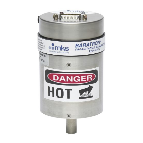
Page 43: Caution Hot" Label
Chapter Three: Overview “Caution Hot” Label The “Caution Hot” label appears on lower portion of the unit since the surface may become hot to the touch during operation. Take all necessary precautions to avoid touching the portion of the unit closest to the sensor port during operation. Figure 6: The “Caution Hot” Label, page 35, shows the location of the “Caution Hot”... - Page 44 Chapter Three: Overview This page intentionally left blank.
-
Page 45: Chapter Four: Operation
(refer to How To Adjust the Zero ZERO Potentiometer, page 38) or at the front panel of any MKS Power Supply/Readout being used. If potentiometer fails to provide sufficient adjustment, the switch may be... -
Page 46: How To Adjust The Zero Potentiometer
Chapter Four: Operation How To Adjust the Zero Potentiometer To adjust the potentiometer: ZERO 1. Install the transducer in a system and connect a power supply/readout. 2. Power the transducer and allow it to warm up and stabilize. Note Allow 2 hours for units to warm up. Ensure that the transducer is fully stabilized before you adjust the zero. -
Page 47: How To Adjust The Coarse Zero Switch
Chapter Four: Operation How To Adjust the Coarse Zero Switch Note Use the switch only if the potentiometer fails to COARSE ZERO ZERO provide sufficient adjustment. To adjust the switch: COARSE ZERO 1. Install the transducer in a system and connect a power supply/readout. 2. -
Page 48: Heater Status Leds And Heater Alarm Relay
Chapter Four: Operation Heater Status LEDs and Heater Alarm Relay The 631D transducer is designed to function at its specified operating temperature by maintaining the sensor temperature within a tight range of the operating temperature. There are two status LEDs, “Htr Fail Status” and “At Temp Status,” that provide a visual indication of the heater condition. -
Page 49: Table 8: Over-Temperature Cutoff Value
Chapter Four: Operation Table 8: Over-Temperature Cutoff Value At Temp Htr Fail State of Heater Conditions Determining Status LEDs and Status Status Alarm Relay Relay Output Contacts Power ON Energized Temp below lower limit of LED temperature window Yellow Pin 13: Open Heater current ON Pin 14: Closed Power ON... - Page 50 Chapter Four: Operation This page intentionally left blank.
-
Page 51: Chapter Five: Optional Relay System
Chapter Five: Optional Solid-State Relay System Chapter Five: Optional Solid-State Relay System General Information The 631D transducer provides the option for two (2) internally mounted trip point relays with user adjustable pressure conditions that will turn ON/OFF each solid state relay. The trip point direction –... -
Page 52: Trip Point Direction
Chapter Five: Optional Solid-State Relay System Trip Point Trip Point Signal Ground Adjustment POTs Access to Trip Point Voltage Signals Figure 8: Location of the Trip Point Adjustment Pots and Trip Point Signal Output Note The trip point adjustment voltage ranges from 0 to 10 Volts, corresponding to the pressure range of the unit zero to full scale. -
Page 53: Figure 9: Led And Relay State When Trip Point Direction Set Above Trip Point Value
Chapter Five: Optional Solid-State Relay System IF Initial Pressure > Trip Point Value LED ON Relay Turned ON LED OFF Relay Turned OFF TRIP POINT VALUE 0.030 Volts TRIP POINT HYSTERESIS IF Initial Pressure < Trip Point Value Final Pressure Figure 9: LED and Relay State When Trip Point Direction Set Above Trip Point Value If the preset direction for Trip Point B is “below”;... - Page 54 Chapter Five: Optional Solid-State Relay System This page intentionally left blank.
-
Page 55: Chapter Six: Maintenance And Troubleshooting
Chapter Six: Maintenance and Troubleshooting Chapter Six: Maintenance and Troubleshooting General Maintenance For best accuracy and repeatability, MKS recommends that you: Zero the unit regularly Follow the procedure described in How To Zero the Type 631D Transducer, page 37, on a regular basis. -
Page 56: Troubleshooting
Material Authorization Number) from the MKS Calibration and Service Center before shipping. The RMA Number expedites handling and ensures proper servicing of your instrument. Refer to the inside of the back cover of this instruction manual for a complete list of MKS Calibration and Service centers. -
Page 57: Appendix A: Product Specifications
Appendix A: Product Specifications Appendix A: Product Specifications Physical Specifications 3.15” diameter, 4.55” length, maximum Dimensions (8.00 cm diameter, 11.55 cm length) Fittings ½” (12.7 mm) tubulation, Swagelok 8-VCR (female), NW-16-KF, 1½” Tri-Clover, 2” Tri-Clover Full Scale Ranges 1, 2, 10, 30, 100, 1000 mmHg (Torr) For other ranges, consult factory Heater Unit Relay Initial State (during operation) -
Page 58: Environmental Specifications
Appendix A: Product Specifications RoHS (Restriction of Hazardous Compliant with Directive 2002/95/EC Substances) Compliance CE Compliance Electromagnetic Compatibility Compliant with EMC Directive 2004/108/EC Temperature Coefficients C Units C Units Zero (≥ 10 Torr ranges) 0.004% F.S./°C 0.008% F.S./°C Zero (<... -
Page 59: Appendix B: Model Code Explanation
Appendix B: Model Code Explanation Appendix B: Model Code Explanation Model Code The options of your transducer are identified in the model code when you order the unit. The model code is identified as follows: 631DWWXYZTUV where: 631D WW Type Number Full Scale Range Engineering Units Fitting... - Page 60 Appendix B: Model Code Explanation Pascal Mbar Fittings (Y) Your fitting choice is designated by a single letter code. Ordering Code ½” diameter tube Swagelok 8-VCR, female NW-16-KF 1½” Tri-Clover 2” Tri-Clover Accuracy (Z) The standard accuracy (±0.5% of Reading) is specified by a letter F in this field. Temperature (T) The operating temperature of the transducer is specified by a single letter.
- Page 61 Appendix B: Model Code Explanation...
- Page 62 Appendix B: Model Code Explanation This page intentionally left blank.
-
Page 63: Index
Index Index Accuracy, 17, 50, 52 Labels, 34, 35 Air flow, 24, 25, 50 hot, 35 Alarm, heater, 40 serial number, 35 wiring diamgram, 34 Cables, 17, 22, 23 CE compliance, 50 Maintenance, 47 Connectors, 30, 31, 33 Manual organization, 18 Customer support, 18 Model code, 51 Mounting, 25, 26... - Page 64 Index Sensor, 17, 26, 29 Sensor fittings, 27 Setup, 25, 26 Signal conditioner, 17, 29 Standard sensor fittings, 27 Temperature coefficients, 50 operating, ambient, 24, 25, 50 operating, sensor, 17, 40, 49, 52 storage, 24, 50 Time response, 50 Trip point relay system, 17, 29, 43 direction, 43, 44, 53 hysteresis, 45 value, 43, 53...
Need help?
Do you have a question about the Baratron 631D and is the answer not in the manual?
Questions and answers