Table of Contents
Advertisement
Advertisement
Table of Contents
Troubleshooting

Subscribe to Our Youtube Channel
Related Manuals for MKS Baratron 722A


Summary of Contents for MKS Baratron 722A
- Page 1 Artisan Technology Group is your source for quality new and certified-used/pre-owned equipment SERVICE CENTER REPAIRS WE BUY USED EQUIPMENT • FAST SHIPPING AND DELIVERY Experienced engineers and technicians on staff Sell your excess, underutilized, and idle used equipment at our full-service, in-house repair center We also offer credit for buy-backs and trade-ins •...
- Page 2 119475-P1 Rev B, 12/00 MKS Baratron Type 722A Absolute Pressure Transducer Artisan Technology Group - Quality Instrumentation ... Guaranteed | (888) 88-SOURCE | www.artisantg.com...
- Page 3 All rights reserved. No part of this work may be reproduced or transmitted in any form or by any means, electronic or mechanical, including photocopying and recording, or by any information storage or retrieval system, except as may be expressly permitted in writing by MKS Instruments, Inc.
-
Page 4: Table Of Contents
Table of Contents Table of Contents Safety Procedures and Precautions ..................... 1 Chapter One: General Information..................... 3 Introduction........................3 How This Manual is Organized ..................4 Customer Support ......................4 Chapter Two: Installation......................5 How To Unpack the Type 722 Unit................5 Unpacking Checklist .................. - Page 5 Table of Contents Label..........................22 Chapter Four: Operation ......................23 General ........................... 23 Lowest Suggested Pressure Available for Reading .......... 23 Lowest Suggested Pressure to Use for Control..........23 Chapter Five: Maintenance and Troubleshooting..............25 General ........................... 25 Zero Adjustment......................25 Troubleshooting ......................
- Page 6 List of Figures and Tables List of Figures and Tables Figures Figure 1: Dimensions of the Low Pressure (up to 1000 Torr) Type 722 Transducer....7 Figure 2: Fitting Dimensions for the Low Pressure Type 722 Transducer........ 7 Figure 3: Dimensions of the High Pressure (>1000 to 25,000 Torr) Type 722 Transducer..8 Figure 4: Fitting Dimensions of the High Pressure Type 722 Transducer ........
- Page 7 List of Figures and Tables Artisan Technology Group - Quality Instrumentation ... Guaranteed | (888) 88-SOURCE | www.artisantg.com...
-
Page 8: Safety Procedures And Precautions
DO NOT SUBSTITUTE PARTS OR MODIFY INSTRUMENT Do not install substitute parts or perform any unauthorized modification to the instrument. Return the instrument to a MKS Calibration and Service Center for service and repair to ensure that all safety features are maintained. - Page 9 Safety Procedures and Precautions CHECK FOR LEAK-TIGHT FITTINGS Before proceeding to instrument setup, carefully check all plumbing connections to the instrument to ensure leak-tight installation. OPERATE AT SAFE INLET PRESSURES This unit should never be operated at pressures higher than the rated maximum pressure (refer to the product specifications for the maximum allowable pressure).
-
Page 10: Chapter One: General Information
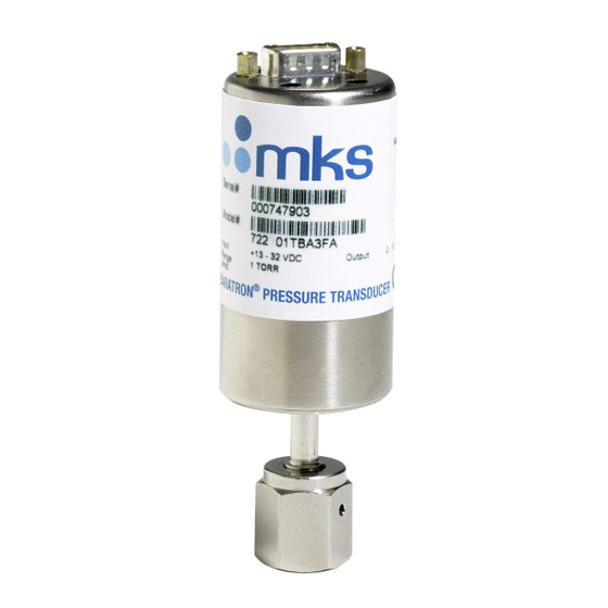
Chapter One: General Information Introduction Chapter One: General Information Introduction The Baratron Type 722A Absolute Pressure Transducer offers the proven technology of the Baratron transducer in a smaller package. The unit provides an accuracy of 0.5% of Reading and carries a CE Mark to indicate full compliance with the EMC Directive 89/336/EEC. -
Page 11: How This Manual Is Organized
Calibration and Service Center before shipping. The ERA Number expedites handling and ensures proper servicing of your instrument. Please refer to the inside of the back cover of this manual for a list of MKS Calibration and Service Centers. Warning All returns to MKS Instruments must be free of harmful, corrosive, radioactive, or toxic materials. -
Page 12: Chapter Two: Installation
Chapter Two: Installation How To Unpack the Type 722 Unit MKS has carefully packed the Type 722 unit so that it will reach you in perfect operating order. Upon receiving the unit, however, you should check for defects, cracks, broken connectors, etc., to be certain that damage has not occurred during shipment. -
Page 13: Product Location And Requirements
Product Location and Requirements Chapter Two: Installation Product Location and Requirements Operating Environmental Requirements • Ambient Operating Temperature: 0° C to 50° C (32° F to 122° F) • Ventilation requirements include sufficient air circulation Dimensions Note All dimensions are listed in inches with millimeters referenced in parentheses. -
Page 14: Figure 1: Dimensions Of The Low Pressure (Up To 1000 Torr) Type 722 Transducer
Chapter Two: Installation Dimensions 1.50 (38.1) Dia. 15-Pin Type "D" Connector 9-Pin Type "D" Connector 6.00 (152) 0.19 (4.7) Screw Access From This Side 5-Pin Terminal Block 2.75 (69.8) Connector Wire Entry 28 AWG to 14 AWG 0.54 (13.7) 0.94 (23.9) Max. -
Page 15: Figure 3: Dimensions Of The High Pressure (>1000 To 25,000 Torr) Type 722 Transducer
Dimensions Chapter Two: Installation 15-Pin Type "D" 1.50 (38.1) Dia. Connector 9-Pin Type "D" Connector 6.00 (152) 0.19 (4.7) Screw Access From This Side 5-Pin Terminal Block Connector 2.68 (68.1) Wire Entry 28 AWG to 14 AWG 0.54 (13.7) Max. 1.36 (34.4) 4-VCR Female Figure 3: Dimensions of the High Pressure (>1000 to 25,000 Torr) Type 722 Transducer... -
Page 16: Setup
Chapter Two: Installation Setup Setup Mounting The 722 transducer can be mounted with the cylindrical end in either a vertical (upright) or horizontal position. The mounting requirements allow any foreign matter entering the pressure port to fall away from the sensing diaphragm. Mounting the Unit in a Vertical Position If the unit is mounted in a vertical position, the cylindrical end of the unit must point upwards, as shown in Figure 5. -
Page 17: Fittings
• • Mini-CF Caution 1. MKS does not warranty the 722 transducer when single or double metal ferrule compression-type vacuum fittings are used because damage will occur to the transducer when improper tightening procedures are followed. 2. Before proceeding to Setup, page 9, carefully check all plumbing connections to the instrument to ensure a leak-tight installation. -
Page 18: Connectors
Chapter Two: Installation Setup Connectors The 722 transducer is available with a 9-pin Type “D”, a 5-pin terminal block connector, or a 15- pin Type “D” on a 6 inch cable Note A “No Connection” pin assignment means that the pin has no internal connection. -
Page 19: Table 3: Pinout Of The 15-Pin Type "D" Connector
Setup Chapter Two: Installation Pinout of the 15-Pin Type “D” Connector Assignment No Connection Pressure Output No Connection No Connection Power Return No Connection + Power Input No Connection No Connection No Connection No Connection Pressure Return No Connection No Connection Chassis Table 3: Pinout of the 15-Pin Type “D”... -
Page 20: How To Wire A Pdr Series Readout To A Type 722 Transducer With A 9-Pin Type "D" Connector
Chapter Two: Installation Setup How to Wire a PDR Series Readout to a Type 722 Transducer with a 9-pin Type “D” Connector. Caution DO NOT use the -15 VDC output of the PDR readout to power the 722 transducer. When the -15 VDC signal of the PDR is connected to the power return of the transducer, a short between the -15 VDC of the transducer and the A GND of the PDR occurs. -
Page 21: Electrical Information
Setup Chapter Two: Installation Electrical Information The 722 transducer requires an external power source capable of supplying the voltages listed in Appendix A: Product Specifications, page 27. Noise and ripple should be less than 2 mV (peak-to-peak) over a 10 kHz bandwidth. You may use any readout device capable of reading from -0.6 V to 11 V. -
Page 22: Interface Cables
Setup Interface Cables Interface cables to all MKS companion products can be purchased from MKS. Refer to Table 5 for a listing of the cable numbers. As of January 1, 1996, all products shipped to the European Community must comply with the EMC Directive 89/336/EEC, which covers radio frequency emissions and immunity tests. - Page 23 Chapter Two: Installation Generic Shielded Cable Description MKS offers a full line of cables for all MKS equipment. Should you choose to manufacture your own cables, follow the guidelines listed below: 1. The cable must have a braided shield, covering all wires. Neither aluminum foil nor spiral shielding will be as effective;...
-
Page 24: Attaching The Terminal Block Connector Cable
Chapter Two: Installation Setup Attaching the Terminal Block Connector Cable The cable to the terminal block connector must be firmly attached to the top of the transducer, in order to comply with CE Mark requirements. Figure 8 shows the preferred method to connect the cable;... -
Page 25: How To Check The Transducer Zero
(or reset) by adjusting the zero potentiometer located on the top cover of the transducer or, on the front panel of an MKS Power Supply/Readout, if you are using one. Refer to Figure 1, page 7, for the location of the zero potentiometer on a low pressure 722 transducer;... -
Page 26: Span Adjustment
Do not adjust the span setting if a calibration transfer standard is not available. Instead, send the unit back to an MKS Service Center for calibration. Artisan Technology Group - Quality Instrumentation ... Guaranteed | (888) 88-SOURCE | www.artisantg.com... - Page 27 How To Check the Transducer Zero Chapter Two: Installation This page intentionally left blank Artisan Technology Group - Quality Instrumentation ... Guaranteed | (888) 88-SOURCE | www.artisantg.com...
-
Page 28: Chapter Three: Overview
An MKS or MKS-compatible power supply is required to complete the pressure to DC voltage output conversion, and an MKS or MKS-compatible display unit is required for direct pressure readout. The display unit could be a personal computer, an MKS pressure controller, or an MKS PDR Series power supply/readout unit. -
Page 29: Signal Conditioning Electronics
Signal Conditioning Electronics Chapter Three: Overview Signal Conditioning Electronics The signal conditioner contains state-of-the-art balanced bridge circuitry, self-compensated for thermal stability with ambient temperature changes. The circuit board construction uses surface mount technology. The output is either a DC voltage or mA current, which is linear with pressure. -
Page 30: Chapter Four: Operation
Chapter Four: Operation General Chapter Four: Operation General After installation and during periodic maintenance, check the transducer zero to verify proper output. If the output is incorrect, set the output by adjusting the zero potentiometer. Refer to How To Check the Transducer Zero, page 18, for zeroing instructions. Lowest Suggested Pressure Available for Reading The pressures listed in the middle column of Table 7 reflect reliable and practical pressures for different range transducers. - Page 31 General Chapter Four: Operation This page intentionally left blank. Artisan Technology Group - Quality Instrumentation ... Guaranteed | (888) 88-SOURCE | www.artisantg.com...
-
Page 32: Chapter Five: Maintenance And Troubleshooting
Any damage should be reported to the carrier and MKS Instruments immediately. If there is no obvious damage and the continuity is correct, obtain an ERA Number (Equipment Return Authorization Number) before returning the unit to MKS Instruments for service. -
Page 33: Troubleshooting
(transducer to electronics Inspect cable and transducer. module). Replace if necessary. Measurement slowly goes Overpressure and/or a build- Return to MKS for servicing positive over time up of contamination in the P or transducer replacement. cavity. Unstable zero output The ambient temperature may Refer to Operating be too high. -
Page 34: Appendix A: Product Specifications
Appendix A: Product Specifications Performance Specifications Appendix A: Product Specifications Performance Specifications Accuracy 0.5% of Reading CE Mark Compliance EMC Directive 89/336/EEC Temperature Coefficients Zero 0.008% of F.S./ °C 10 Torr through 25,000 Torr 0.020% of F.S./ °C 1 Torr Span 0.04% of Rdg./ °C Physical Specifications... -
Page 35: Electrical Specifications
Electrical Specifications Appendix A: Product Specifications Warning Units with NW-16-KF fittings and a full scale range greater than 1200 Torr (23 psi) require an HPS overpressure ring. Operating the unit without a protective overpressure ring may result in injury. The HPS part number for the overpressure ring is HPS 10031. Electrical Specifications Input Required 0 to 5 Volt output... -
Page 36: Appendix B: Model Code Explanation
Appendix B: Model Code Explanation Model Code Appendix B: Model Code Explanation Model Code The options of your transducer are identified in the model code when you order the unit. The model code is identified as follows: 722AXXXYYZF# where: 722A Type Number Full Scale Range Fittings... - Page 37 Model Code Appendix B: Model Code Explanation Full Scale Range (XXX) The full scale range is indicated by a two digit / one letter code. Full Scale Range Ordering Code 1,000* 5,000* 10,000* 25,000* *must include a fitting. Fittings (YY) Six types of fittings are available, designated by a two letter code.
-
Page 38: Nw-16-Kf Fitting Information
Appendix B: Model Code Explanation NW-16-KF Fitting Information NW-16-KF Fitting Information The NW-16-KF fittings are only available for units with full scale pressure of a maximum of 5000 Torr (100 psia). Warning Units with NW-16-KF fittings and a full scale range greater than 1200 Torr (23 psi) require an HPS overpressure ring. - Page 39 NW-16-KF Fitting Information Appendix B: Model Code Explanation This page intentionally left blank. Artisan Technology Group - Quality Instrumentation ... Guaranteed | (888) 88-SOURCE | www.artisantg.com...
-
Page 40: Index
Index Index Accuracy, 3, 27, 31 Options, 3 Orientation, 9, 18 Cables, interface, 15 CE Mark, 3, 15, 27 Pinout Connectors, 3, 11, 31 15-pin Type "D", 11 Customer support, 4 5-pin terminal block, 11 9-pin Type, 11 Power, 30 Dimensions, 6–8 Pressure limit, 27 Pressure, lowest for control, 23... - Page 41 Index Zero, 18 Zero adjustment, 25 Artisan Technology Group - Quality Instrumentation ... Guaranteed | (888) 88-SOURCE | www.artisantg.com...
- Page 42 Artisan Technology Group is your source for quality new and certified-used/pre-owned equipment SERVICE CENTER REPAIRS WE BUY USED EQUIPMENT • FAST SHIPPING AND DELIVERY Experienced engineers and technicians on staff Sell your excess, underutilized, and idle used equipment at our full-service, in-house repair center We also offer credit for buy-backs and trade-ins •...
Need help?
Do you have a question about the Baratron 722A and is the answer not in the manual?
Questions and answers