
Subscribe to Our Youtube Channel
Related Manuals for MKS DualTrans 910


Summary of Contents for MKS DualTrans 910
- Page 1 910 DualTrans™ Vacuum Pressure Transducer RS232 / RS485 / Display Operation and Installation Manual P/N: 100017123 910 DualTrans Transducer Operation and Installation Manual Revision: G, February 2020 pg. 1...
-
Page 2: Warranty Information
Visit our website at: www.mksinst.com Warranty Information MKS Instruments, Inc. provides an eighteen (18) month warranty from the date of shipment for new MKS products. The MKS Instruments, Inc. general terms and conditions of sale provide the complete and exclusive warranty for MKS products. This document is located on our web site at www.mksinst.com, or may be obtained by a contacting an MKS customer service representative. -
Page 3: Table Of Contents
This document contains confidential proprietary information belonging to MKS Instruments, Inc. This information is not for publication and has been provided to MKS on the condition that it not be copied, reproduced or disclosed, either wholly or in part, to third parties without the expressed written consent of MKS Instruments, Inc. -
Page 4: Safety Information
Service and Repair page 52. Do not install substituted parts or perform any unauthorized modification to the transducer. Return the instrument to a MKS Calibration and Service Center for service and repair to ensure all of the safety features are maintained. -
Page 5: Unpacking
Short form manual 100017096 Documentation & Software CD If any items are missing, call MKS Customer Service at +1-833-986-1686 or your local MKS sales office or distributor. Part number The 910 part number system has 5 digits that identify flange, communication interface, analog output type, I/O connector and sensor sealing type. -
Page 6: Description
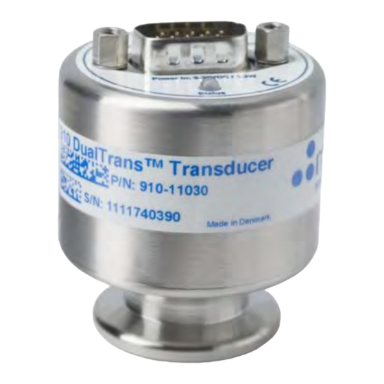
Description The 910 DualTrans vacuum transducer offers a wide measuring range from 1×10 to 1000 Torr and is based on measurement of thermal conductivity and measurement of mechanical deflection of a silicon membrane. The 910 can be used in a variety of applications as standalone unit or with the PDR900 display and controller unit. -
Page 7: 910 Functions
910 Functions User Switch I/O Connector Red or Green LED Status Indicator User Switch The user switch has the following functions: 1. Vacuum Zero adjustment (VAC! Command) 2. Transducer firmware upgrade mode Refer to pages 17, 18 and 48 for operation procedure. If the user switch is activated by accident and vacuum Zero or Atmospheric adjustment is executed ... -
Page 8: Transducer Installation (Mechanical)
Transducer installation (mechanical) Do not use or install the 910 transducer where the following conditions occur: - Temperatures lower than 0 C or higher than 40 - Corrosive or explosive gases - Direct sunlight or other heat sources Process compatibility The 910 transducer is intended for use in relatively clean environments. -
Page 9: Transducer Installation (Electrical)
Transducer installation (electrical) The 910 is available with different input/output connectors. Use a cable with strain relief to ensure proper electrical connection and to reduce stress on the connectors. Ensure a low impedance electrical connection between the 910 transducer body and the ... - Page 10 Input/Output Wiring To comply with EN61326-1 immunity requirements, use a braided shielded cable. Connect the braid to the metal hoods at both ends of the cable with the end for power supply connected to earth ground. 910 I/O Connector (15 pin) PIN Description RS485- / RS232 Transmit RS485+ / RS232 Receive...
-
Page 11: Serial User Interface
Serial user interface The 910 is as standard supplied with RS232 or RS485 user interface. The user interface allows change of transducer parameters like set point settings and calibration. The serial interface uses the following data format: 8 data bits, 1 stop bit and no parity bit. RS232 user interface The 910 is DCE (Data Communication Equipment) and can be connected to DTE (Data Terminal Equipment), typically a... -
Page 12: Communication Protocol
To the right is illustrated the Windows communication port properties for communicating with transducer factory default settings. MKS also offers communication software examples that can be downloaded at: www.mksinst.com/vtsw/ In OEM applications transducer communication software routines are normally integrated with other system control software. - Page 13 The transducer will reply in the current baud rate and then change to the new value. Addressing The transducer uses an addressable communication protocol that allows multiple MKS 900 Series transducer devices to be connected in a RS485 network. The address is required in both RS232 and RS485 communication.
-
Page 14: Setpoint Relays
Setpoint relays The 910 can be ordered with 3 mechanical relays that can be used for controlling external process equipment. The relay has closing and breaking contacts which are rated 30 VDC, 1A resistive load. If the transducer is supplied without setpoint relays, the setpoint commands can still be accessed. Refer to part number definition page 3 to verify if setpoint relays are included. - Page 15 When using the setpoint relay to control process equipment, always take appropriate precautions to prevent system damage in case of transducer power failure. The NC contact will be closed in case of transducer power failure. If the transducer is supplied as a special version (P/N: 910-xxxxx-xxxx) with pre-configured ...
-
Page 16: Integrated Touch Display
Setpoint safety delay The setpoint safety delay function requires 5 continuous measurements that exceed setpoint value before the relay is tripped. This feature prevents false trigging of the setpoint relay due to noise. If fast setpoint response is required, the setpoint safety delay can be disabled. Setpoint safety delay Command: @253SPD!ON;FF... - Page 17 Main screen. The following table shows the different menus and options available: Display-screen Information Start-up MKS logo and transducer model Home The Home screen shows the current pressure, the transducer model, the status of the setpoints, the triggering direction of each setpoint and shows if an alarm is enabled.
- Page 18 Pressure output The 910 transducer can provide pressure measurement output as an analog voltage or RS232/RS485 digital value. The digital value is 3 digits scientific notation for PR1, PR2 and PR3 reading and 4 digits for PR4 reading. Pressure request: Query: @253PR1?;FF Query reply:...
-
Page 19: Calibration And Adjustment
Resolution The digital pressure output can provide 3 digit or 4 digit values; however, the resolution is limited in certain parts of the measuring range. 1.00E-5 to 1.00E-4 Torr 1 digit resolution 1.000E-5 1.00E-4 to 1.00E-3 Torr 2 digit resolution 1.200E-4 1.00E-3 to 900 Torr 3 or 4 digit resolution... - Page 20 MicroPirani Zero Adjustment by serial interface The zero adjustment function changes the MicroPirani measurement offset at low pressure. Temporary or permanent shift in zero offset can be caused by contamination, corrosion, electrical noise interference and temperature. Zero adjustment only changes the low measuring range and will have no influence on measuring errors in the range from 1×10 and above.
-
Page 21: Factory Default
Analog out 1: AO1! × Analog out 2: AO2! × (1) If the transducer is delivered with other analog output than standard mks (part number specified), then the factory default value will be specified by the specials part number. pg. 21... -
Page 22: Transducer Lock Function
The 910 transducer can be delivered with factory locked tamperproof settings for safety interlock applications. This option is defined in the special settings. If delivered with factory lock the transducer settings can only be changed if returned to MKS. pg. 22... -
Page 23: User Switch Command
User Switch Command The User Switch function can be disabled to prevent accidental execution of zero and atmospheric adjustments. Command: @253SW!OFF;FF Command values: ON,OFF Command reply: @253ACK;FF Query: @253SW?;FF Query reply: @253ACKON;FF Factory default: Transducer test The transducer test command can be used to visually identify a transducer. If the test mode is enabled the LED will flash with a 1 sec. -
Page 24: Analog Output
Pascal Pascal The standard MKS analog output always provides 1 VDC/decade. If the transducer pressure unit is changed from Torr to Pascal or mbar the analog output scaling will change as well, so it represents 1 VDC/decade Torr or 1 VDC/decade mbar or Pascal. - Page 25 9 = MKS Moducell 325 (x3) 10 = MKS Baratron 0.1 Torr (0-10 VDC) 11 = MKS Baratron 1 Torr (0-10 VDC) / Hasting 2002OBE, Channel 2 12 = MKS Baratron 10 Torr (0-10 VDC) 13 = MKS Baratron 100 Torr (0-10 VDC)
- Page 26 The 910 is available with dual analog output which can be used to provide an alternative output for amplification of range or to emulate another transducer type while still using the MKS standard output. This feature is a hardware option and must be specially ordered. Refer to part number specifications page 3.
- Page 27 Analog output calibration = 2 (Edwards APG-100 emulation) The APG-L emulation provides a log linear output of 1 VDC/mbar decade. = 10 = log )+6.125 (Vout – 6.125) Torr Torr = 10 = log (Vout – 6) mbar mbar = 10 = log (Vout –...
- Page 28 Analog output calibration = 4 (Inficon PSG500 / Oerlikon TTR91) The TTR91 emulation provides a log linear output. The output does not provide a pressure dependent signal at pressures below 2.00E-4 Torr. = 10 = log ) ×1.286+6.304 ((Vout -6.304)/1.286) Torr Torr = 10...
- Page 29 1.33E+02 1.33E+04 9.343 7.60E+02 1.01E+03 1.01E+05 10.004 Analog output calibration = 7 (MKS GP275 emulation) The GP275 emulation provides a strongly nonlinear output with very poor resolution in the low range and close to atmospheric pressure. Torr mbar Pascal Vout 1.00E-05...
- Page 30 1.07E+05 3.2398 Analog out calibration = 9 (MKS Moducell 325, amplified 3 times) The Moducell x3 emulation is in curve form identical with the standard Moducell; however, to provide better signal resolution the signal is amplified by a factor of three.
- Page 31 Analog out calibration = 10 (MKS Baratron 0.1 Torr) The 0.1 Torr Baratron emulation provides a signal directly proportional with pressure with a full scale reading of 10 VDC at 0.1 Torr. Torr mbar Pascal Vout 1.00E-3 1.33E-3 1.33E-1 0.100 5.00E-3...
- Page 32 Analog out calibration = 13 (MKS Baratron 100 Torr) The 100 Torr Baratron emulation provides a signal directly proportional with pressure with a full scale reading of 10 VDC at 100 Torr. Torr mbar Pascal Vout 1.33 1.333E+2 0.100 6.66 6.66E+2...
- Page 33 Analog out calibration = 15 (Piezo analog output) Torr mbar Pascal Vout -8.00E+2 -1.07E+3 -1.07E+5 1.10 -7.00E+2 -9.33E+2 -9.33E+4 1.15 -6.00E+2 -8.00E+2 -8.00E+4 1.22 -5.00E+2 -6.67E+2 -6.67E+4 1.30 -4.00E+2 -5.33E+2 -5.33E+4 1.40 -3.00E+2 -4.00E+2 -4.00E+4 1.52 -2.00E+2 -2.67E+2 -2.67E+4 1.70 -1.00E+2 -1.33E+2 -1.33E+4...
- Page 34 Analog out calibration = 16 (Edwards AIM-S /-SL) The Edwards AIM-S / SL emulation provides a strongly non linear output. The 910 provides only values above 1.00E-5 Torr. Torr mbar Pascal Vout 1.00E-8 1.33E-8 1.33E-6 1.80E-8 2.40E-8 2.40E-6 4.40E-8 5.87E-8 5.87E-6 6.10E-8 8.13E-8...
- Page 35 Analog out calibration = 18 (Pfeiffer IKR251) The Pfeiffer IKR251 emulation provides a log linear output. The 910 provides only values above 1E-5 Torr. Torr mbar Pascal Vout 5.00E-9 6.67E-9 6.67E-7 2.3240 1.00E-8 1.33E-8 1.33E-6 2.6250 5.00E-8 6.67E-8 6.67E-6 3.3240 1.00E-7 1.33E-7 1.33E-5...
- Page 36 Analog out calibration = 20 (OBE Special) The OBE special emulation provides a linear output from 1 to 1000 Torr. Torr mbar Pascal Vout 1.33E-01 1.33E+01 1.33E+00 1.33E+02 2.67E+00 2.67E+02 5.005 5.33E+00 5.33E+02 5.015 6.67E+00 6.67E+02 5.02 1.33E+01 1.33E+03 5.045 3.33E+01 3.33E+03 5.12...
- Page 37 Analog Output calibration = 23 (MKS GP275 Emulation 9 VDC FS) The GP275 emulation with 9VDC full scale provides a strongly non linear output with very poor resolution in the low range and close to atmospheric pressure. Torr mbar Pascal Vout 1.00E-03...
- Page 38 1.00E+03 1.00E+05 9.99 Analog Output calibration = 25 (MKS GP275 Emulation 5.6 VDC FS) The GP275 emulation with 5.6VDC full scale provides a strongly non linear output with very poor resolution in the low range and close to atmospheric pressure.
- Page 39 Analog Output calibration = 26 (Edwards APG100-LC) The APG100-L emulation provides a strongly none linear output with limited resolution in the low range and close to atmosphere. Torr mbar Pascal Vout 7.50E-06 1.00E-05 1.00E-03 1.70E-04 2.27E-04 2.27E-02 3.75E-04 5.00E-04 5.00E-02 8.10E-04 1.08E-03 1.08E-01...
- Page 40 Analog Output calibration = 27 (Edwards APG100-M) The APG100-M emulation provides a strongly none linear output with limited resolution in the low range and close to atmosphere Torr mbar Pascal Vout 7.50E-05 1.00E-04 1.00E-02 1.73E-04 2.31E-04 2.31E-02 2.05 4.66E-04 6.21E-04 6.21E-02 1.02E-03 1.36E-03...
- Page 41 Analog Output calibration = 28 (MKS 907) Torr mbar Pascal Vout 7.50E-04 1.00E-03 1.00E-01 0.387 1.50E-03 2.00E-03 2.00E-01 0.397 3.00E-03 4.00E-03 4.00E-01 0.418 4.50E-03 6.00E-03 6.00E-01 0.437 6.00E-03 8.00E-03 8.00E-01 0.456 7.50E-03 1.00E-02 1.00E+00 0.473 1.50E-02 2.00E-02 2.00E+00 0.551 2.25E-02 3.00E-02...
- Page 42 Analog Output calibration = 29 (K6080) Torr mbar Pascal Vout 7.50E-06 1.00E-05 1.00E-03 3.75E-05 5.00E-05 5.00E-03 7.50E-05 1.00E-04 1.00E-02 3.00E-04 4.00E-04 4.00E-02 6.00E-04 8.00E-04 8.00E-02 7.50E-04 1.00E-03 1.00E-01 0.41 3.00E-03 4.00E-03 4.00E-01 0.48 3.75E-03 5.00E-03 5.00E-01 6.75E-03 9.00E-03 9.00E-01 0.55 1.50E-02 2.00E-02 2.00E+00...
-
Page 43: Analog Output Calibration = 31 (Varian Eysys)
5.25E-01 7.00E-01 7.00E+01 8.75 7.50E-01 1.00E+00 1.00E+02 1.50E+00 2.00E+00 2.00E+02 2.25E+00 3.00E+00 3.00E+02 Analog Output calibration = 33 (MKS 685) P = 10 (Vout – 4) = 4 + log Torr mbar Pascal Vout 1.00E-05 1.33E-05 1.33E-03 1.00 1.00E-04 1.33E-04 1.33E-02... - Page 44 MicroPirani gas dependence The 910 MicroPirani is based on measurement of thermal conductivity and consequently its reading depends on gas and gas concentration. The 910 has calibration curves for a number of common gases. For gas setup refer to gas calibration page 19. The 910 is per factory default calibrated for Nitrogen gas and below is showed the 910 Nitrogen MicroPirani reading in different gas types.
- Page 45 Argon gas dependence Hydrogen gas dependence pg. 45...
-
Page 46: Query Command List
Setpoint safety delay Transducer information Command Response Explanation @xxxMD?;FF @xxxACK910;FF Model number (910) @xxxDT?;FF @xxxACKDUALTRANS;FF Device type name (DualTrans) @xxxMF?;FF @xxxACKMKS;FF Manufacturer name (MKS) @xxxHV?;FF @xxxACKA;FF Hardware version @xxxFV?;FF @xxxACK1.00;FF Firmware version @xxxSN?;FF @xxxACK11350123456;FF Serial number @xxxSW?;FF @xxxACKON;FF Switch enable @xxxTIM?;FF... -
Page 47: Setup And Configuration Command List
Setup and configuration command list Setpoint setup and configuration Command Response Explanation @xxxSP1!2.00E+1;FF @xxxACK2.00E+1;FF Set point 1-3 switch value. @xxxSP2!2.00E+1;FF @xxxSP3!2.00E+1;FF @xxxSH1!5.00E+1;FF @xxxACK5.00E+1;FF Set point 1-3 hysteresis switch value. @xxxSH2!5.00E+1;FF @xxxSH3!5.00E+1;FF @xxxEN1!ON;FF @xxxACKON;FF Set point 1-3 enable status (ON or OFF) @xxxEN2!ON;FF @xxxEN3!ON;FF @xxxSD1!BELOW;FF... -
Page 48: Firmware Upgrades (Rs232 Only)
3. Hold down the User switch while turning power on 4. Release the User switch 5. Run the 900 Series firmware download software and start download Transducer with RS485 interface cannot be firmware upgraded by the user. Contact MKS customer service for upgrade. pg. 48... -
Page 49: Faq
FAQ (Frequently Asked Questions Applications Q: Can the transducer and sensor element continuously withstand vibrations from a mechanical fore-pump. A: Yes – the MEMS MicroPirani sensor element can withstand continuous vibrations. Q: Is the transducer compatible with fluorine gases? A: No – the 910 is not intended for use in aggressive environments like semiconductor etch applications. Q: When the transducer is pumped down and isolated by closing a valve the pressure is raising. - Page 50 Q: Reverse voltage has been connected to power supply input. Is the transducer damaged? A: Not likely – the transducer power supply circuit has reverse voltage and over voltage protection, however, MKS cannot guarantee that the transducer will not be damaged. Q: The status LED is constantly illuminating red? A: The red status indicates a defect MicroPirani sensor element most likely damaged by corrosion or contamination.
-
Page 51: Trouble Shooting
Trouble shooting Symptom Possible Cause/Remedy No digital communication Check electrical connections (3 wires from transducer to communication equipment) Transducer and communication equipment baud rate matches Use of incorrect transducer address. Try address 254 Attention characters missing (@) Termination characters missing (;FF) NAK180 is received when The transducer setup is locked. -
Page 52: Service And Repair
910 Transducer. After the installation of the repair kit the transducer will be operating as a new transducer. Transducers with integrated display (P/N: 910-xxxx4 and 910-xxxx6) cannot be disassembled by user and must sent to MKS service facility for repair. 910 Transducer repair kit Part number... -
Page 53: Specifications
± 0.2% of reading Supply Voltage: 9 – 30 VDC Power consumption: < 1.2 Watt Fuse (thermal recoverable): 200 mA Analog output (MKS standard): 1-9 VDC Analog output 1 resolution: 16 bit Analog output 2 resolution: 12 bit Analog output impedance: 100 Ω... -
Page 54: Dimensions
Dimensions KF16 flange (P/N: 910-1xxx) mm. [Inch.] Dimensions KF16 long flange (P/N: 910-8xxx) mm. [Inch.] Dimensions KF25 flange (P/N: 910-2xxx) mm. [Inch.] pg. 54... - Page 55 Dimensions VCR4 flange (P/N: 910-4xxx) mm. [Inch.] Dimensions VCR8 flange (P/N: 910-5xxx) mm. [Inch.] pg. 55...
- Page 56 Dimensions NPT 1/8” flange (P/N: 910-3xxx) mm. [Inch.] pg. 56...
-
Page 57: Accessories And Replacement Part Numbers
Accessories and replacement part numbers PDR900 controller Part number Description Interface PDR900-12-EU PDR900 Controller EU Schuko power cable PDR900-12-US PDR900 Controller US power cable PDR900-12-UK PDR900 Controller UK power cable PDR900-12-JP PDR900 Controller JP power cable. mbar / Pascal unit PDR900-12-DK PDR900 Controller Danish power cable... -
Page 58: Pdr 900 Display And Power Supply
PDR 900 Display and power supply • Plug and play readout for 900 Series transducers • The easy way for setup and configuration • Data logger tool for data analysing See m or e on : w ww .m k s i n st. co m /p d r 90 0 91 0 DualTrans transducer with integrated display •... -
Page 59: Index
Index Accessories and replacement part numbers ..57 Model ..............22 Accuracy ............. 53 Moducell 325 ............30 Accuracy and repeatability........17 Addressing ............11 NAK Code ............10 Analog output ..........23; 49 NAK180 ..........13; 21; 51 Applications ............ 4; 49 Argon gas ............ - Page 60 910 DualTrans™ Vacuum Pressure Transducer RS232 / RS485 / Display Operation and Installation Manual P/N: 100017123 910 DualTrans Transducer Operation and Installation Manual Revision: G, February 2020...
Need help?
Do you have a question about the DualTrans 910 and is the answer not in the manual?
Questions and answers