Table of Contents
Advertisement
Advertisement
Table of Contents

Related Manuals for CAB XC Series


Summary of Contents for CAB XC Series
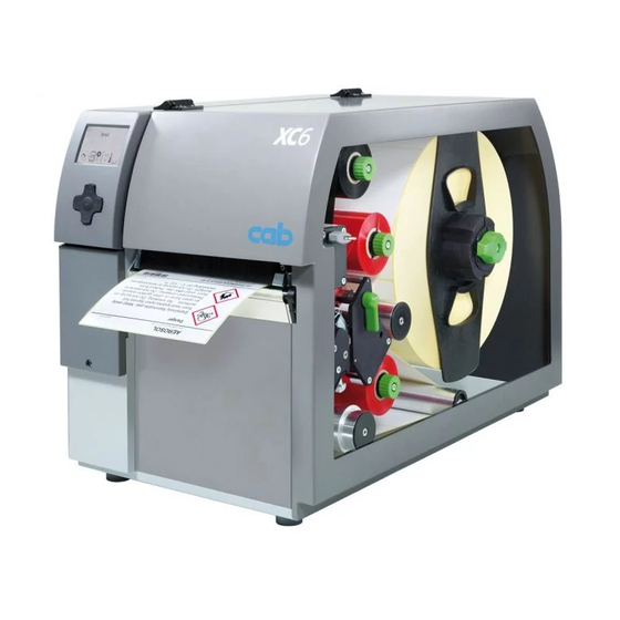
- Page 1 Service Manual Label Printer XC Series...
- Page 2 Editor Regarding questions or comments please contact cab Produkt- technik GmbH & Co. KG. Topicality Due to the constant further development of our products discrep- ancies between documentation and product can occur.
-
Page 3: Table Of Contents
Table of Contents Important Information ..........................4 Instructions ............................... 4 General Safety Instructions ........................4 Protective Devices ........................... 5 Handling Electricity ..........................5 Procedure in Case of Accidents ......................5 Preparation ............................. 6 Tools ................................. 6 Removing and Installing the Rear Cover ....................6 Cleaning .............................. -
Page 4: Important Information
Important Information Instructions Important information and instructions in this documentation are designated as follows: Danger! Draws your attention to an exceptionally grave, impending danger to your health or life. Warning! Indicates a hazardous situation that could lead to injuries or material damage. Attention! Draws attention to possible dangers, material damage or loss of quality. -
Page 5: Protective Devices
Important Information Protective Devices Warning! There is a risk of injury if protective devices are missing or defective. Replace all protective devices (covers, safety notices, grounding cables etc) after maintenance work has been completed. Replace parts that have become defective or unusable. Wear protective goggles for: •... -
Page 6: Preparation
Only use tools and testing devices that are suitable for the task at hand. cab special tools: • Test collar for transfer ribbon winder (cab item number: 5534199) • Distance caliber 0,1 mm (cab item number: 5961064) Standard tools: •... -
Page 7: Cleaning
Cleaning Cleaning by the Operator The following cleaning work is described in the “Operator's Manual“: • cleaning the device • cleaning the printhead • cleaning the print roller Cleaning the Label Sensor Fig. 2 Cleaning the label sensor Danger! Risk of death via electric shock! ... -
Page 8: Replacing Assembly Units
Replacing Assembly Units Replacing the Printhead 4.1.1 Replacing the Printhead XC4 The printhead of the label printer can be replaced without the need for fine adjustment. The printhead must be replaced if worn. 1 Printhead 2 Plug connection 3 Plug connection 4 Screw 5 Printing line 6 Pins... - Page 9 Replacing Assembly Units Notice! The printhead replacement will be described for the upper printhead. The procedure applies for the lower printhead in the same manner. Removing the printhead 1. Lift the printhead. 2. Remove labels and transfer ribbon from the printer. 3.
-
Page 10: Replacing The Printhead Xc6
Replacing Assembly Units 4.1.2 Replacing the Printhead XC6 1 Printhead 2 Plug connection 3 Plug connection 4 Threaded hole 5 Printing line Fig. 5 Structure of the printhead XC6 Attention! The printhead can be damaged by static electricity discharges and impacts! ... - Page 11 Replacing Assembly Units 6. For replacing the lower printhead remove the lower print roller 4.2 on page 12 and guide the printhead downward between the print units (8,9). 7. Loosen both plug connections (2, 3) on the printhead. Fig. 7 Replacing the lower printhead XC6 Installing the printhead 1.
-
Page 12: Replacing The Print Roller
Replacing Assembly Units Replacing the Print Roller 6c 6b 7c 7b 7a Fig. 9 Replacing the print rollers 1. Unlock the levers (10,11) and lift the printheads. 2. Loosen the screws (6,7) and remove the plates (5,9). 3. Remove the print rollers (2,3). 4. -
Page 13: Replacing The Slipping Clutches
Replacing Assembly Units Replacing the Slipping Clutches The rewinders for the transfer ribbon are coupled to slipping clutches (1) in the main drive. The supply hubs of the transfer ribbon are braked with a slipping clutches (2) during printing. Change a slipping clutch when it can no longer be set 5.1 on page 19. Removal and installation of the slipping clutch is also required for replacement of a winder. - Page 14 Replacing Assembly Units Installing the slipping clutches on the rewinders Fig. 11 Slipping clutch on the rewinder 1. Slide coupling (2) onto the winder axis (4). 2. Align grooves in the coupling disks (3) with the guides in the collar of the belt wheel (5). 3.
-
Page 15: Replacing The Brake Block On The Roll Retainer
Replacing Assembly Units Replacing the Brake Block on the Roll Retainer 9/4x Fig. 13 Brake on the roll retainer 1. Turn knob (7) clockwise to release the roll retainer and remove the margin stop (10) from the roll retainer. 2. Loosen 4 screws (9) an remove wall spacer (8). 3. -
Page 16: Replacing The Label Sensor
Replacing Assembly Units Replacing the Label Sensor Notice! Soiling of the label sensor can also cause malfunctions. Before replacing the label sensor, check whether it is soiled and clean it if necessary 3.2 on page 7. Danger! Risk of death via electric shock! ... -
Page 17: Replacing The Cpu
Replacing Assembly Units Replacing the CPU Danger! Risk of death via electric shock! Before opening the rear cover, disconnect the device from the mains supply and wait at lease one minute until the power supply unit has discharged. Removing the CPU 1. -
Page 18: Replacing The Power Supply Unit
Replacing Assembly Units Replacing the Power Supply Unit Danger! Risk of death via electric shock! Before opening the rear cover, disconnect the device from the mains supply and wait at lease one minute until the power supply unit has discharged. Removing the power supply unit 1. -
Page 19: Adjustments
Adjustments Measuring and Adjusting the Winding Torques The rewinders for the transfer ribbon are coupled to slipping clutches in the main drive. The supply hubs of the transfer ribbon are braked with a slipping clutches during printing. The correct setting of the torques of these slipping clutches is necessary for: •... - Page 20 Adjustments The set values for the winding torque and the resulting pulling force at the test collar are: Slipping clutch on Direction of rotation Winding torque M Pulling force F Ribbon take up hub against the winding direction 7,5 - 10,5 Ncm 2,5 - 3,5 N Ribbon supply hub 3,6 - 4,5 Ncm...
-
Page 21: Adjusting The Slipping Clutches
Adjustments 5.1.2 Adjusting the Slipping Clutches The winding torque of a winder can be changed at the knurled ring of the respective slipping clutch. The numbers on the knurled ring stand for the value of the winding torque: • 1: Lowest winding torque •... -
Page 22: Adjusting The Printing Mechanism
Adjustments Adjusting the Printing Mechanism Major adjustment of the printing mechanism beyond format-based settings is only required if the printhead assembly has been removed or parts in this area have been replaced. Excluded from this is the replacement of the printhead, after which readjustment is generally not required. -
Page 23: Adjusting The Printhead Position
Adjustments 5.2.2 Adjusting the Printhead Position In order to achieve the best possible print image the following printhead settings are necessary: • Align the heating line with the highest point of the print roller. Density of the print image is the greatest at this point. -
Page 24: Adjusting The Printhead Pressure
Adjustments 5.2.3 Adjusting the Printhead Pressure The printhead pressure can be changed with the screws (1a) and (1b) at the inside and outside of the printhead. Increasing the head contact pressure leads to an improvement of the print image density on the corresponding side and to a shifting of the ribbon feed path in the corresponding direction. -
Page 25: Adjusting The Transfer Ribbon Feed Path
Reset the Heat level to 0 in the printer configuration Configuration Manual. Recheck the setting with the test function Test grid ( Configuration Manual) or a similar print pattern. When using standard cab media, the test printout must show lines with sharp contours and black areas without any parts missing. -
Page 26: Adjusting The Label Feed Path
Adjustments Adjusting the Label Feed Path You can adjust the label feed path by skewing the roller below the lower print unit. If a clear lateral drift of the labels occurs the label feed path can be adjusted by turning the eccentric (2). 2 3a Fig. -
Page 27: Adjusting The Belt Tension
Adjustments Adjusting the Belt Tension Danger! Risk of death via electric shock! Before opening the rear cover, disconnect the device from the mains supply and wait at lease one minute until the power supply unit has discharged. up to SN 120132 Fig. - Page 28 Adjustments from SN 120133 Fig. 26 Adjusting the belt tension (from SN 120133) 1. Unplug the printer from the electrical outlet. 2. Remove the cover 2.2 on page 6. 3. For adjusting the ribbon rewinder drive belt (3) : •...
-
Page 29: Adjusting The Head Switch
Adjustments Adjusting the Head Switch The head switches prevent printing from occurring when a printhead is open. Adjust the head switches if the error message Head open appears in the display even though the printheads are locked. Danger! Risk of death via electric shock! ... -
Page 30: Adjusting The Magnetic Clutch
Adjustments Adjusting the Magnetic Clutch A misaligned magnetic clutch can cause a very high and not adjustable torque at the ribbon supply hub of the lower print unit. The distance between chassis of the magnetic clutch (2) and the armature disk (1) must be 0.1 mm . Danger! Risk of death via electric shock! ... -
Page 31: Adjusting The Ribbon Saver Mechanics
Adjustments Adjusting the Ribbon Saver Mechanics The lower print unit is equipped with a ribbon saver. The saver automatic reduced the consumption of color ribbon, because in case of the saver mode the movement will interrupted by lifting the printhead. This is operated by a eccentric, which is controlled by a light sensor. -
Page 32: Troubleshooting And Error Treatment
Troubleshooting and Error Treatment Failure of Device Functions Functional error Possible remedy Medium is not transported Check electrical connections between CPU and stepper motor media transport Check drive mechanism Replace the CPU Replace the stepper motor media transport No print image with medium Check plug connections at the printhead transport Examine printhead cable for damage and replace if necessary... -
Page 33: Hardware Faults
Troubleshooting and Error Treatment Hardware Faults Error message Cause Fault recovery ADC malfunction Fault on the CPU Replace the CPU FPGA malfunction Fault on the CPU Replace the CPU Invalid setup Fault on the CPU Replace the CPU Voltage error Voltage of the battery on the Replace the CPU CPU is too low... -
Page 34: Block Diagram
Block Diagram Fig. 32 Block diagram... -
Page 35: Layout Diagram Cpu
Layout Diagram CPU Fig. 33 Layout diagram CPU - components side... - Page 36 Layout Diagram CPU Fig. 34 Layout diagram CPU - soldering side with measuring points...
-
Page 37: Index
Index Accidents ..........5 Safety instructions ......4 Sensor ribbon saver ......31 Slipping clutch Belt tension ........27 adjusting ........21 Block diagram ........34 replacing ........13 Brake block roll retainer ....15 Test grid ..........23 Tools ...........6 Cleaning ..........7 CPU replacement ......17 Winding torque adjusting ........21 Distance caliber 0.1 mm ....30 measuring ........19 Electricity ..........5...
Need help?
Do you have a question about the XC Series and is the answer not in the manual?
Questions and answers