cab SQUIX Manual
- Configuration manual (64 pages) ,
- Operator's manual (36 pages) ,
- Service manual (28 pages)
Advertisement
Introduction
Instructions
Important information and instructions in this documentation are designated as follows:

Draws attention to an exceptionally great, imminent danger to your health or life due to hazardous voltages.

Draws attention to a danger with high risk which, if not avoided, may result in death or serious injury.

Draws attention to a danger with medium risk which, if not avoided, may result in death or serious injury.

Draws attention to a danger with low risk which, if not avoided, may result in minor or moderate injury.
 Attention!
Draws attention to potential risks of property damage or loss of quality.
 Note!
Note!
Advices to make work routine easier or on important steps to be carried out.
 Handling instruction
 Reference to section, position, illustration number or document.
* Option (accessories, peripheral equipment, special fittings).
Time Information in the display.
Intended Use
- The device is manufactured in accordance with the current technological status and the recognized safety rules. However, danger to the life and limb of the user or third parties and/or damage to the device and other tangible assets can arise during use.
- The device may only be used for its intended purpose and if it is in perfect working order, and it must be used with regard to safety and dangers as stated in the operating manual.
- The device printer is intended exclusively for printing suitable materials. Any other use or use going beyond this shall be regarded as improper use. The manufacturer/supplier shall not be liable for damage resulting from unauthorized use; the user shall bear the risk alone.
- Usage for the intended purpose also includes complying with the operating manual, including the manufacturer's maintenance recommendations and specifications.
Installation
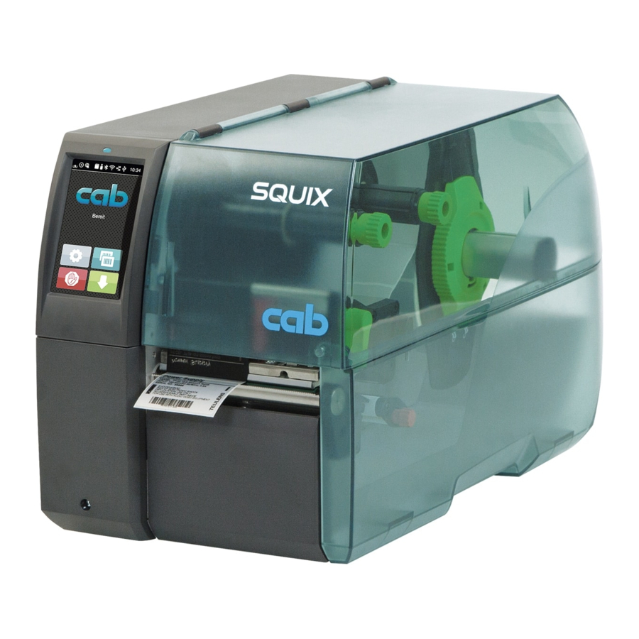
Device Overview
Figure 1 Overview

- Cover
- Margin stop (only devices with centered media guiding)
- Margin stop
- Roll retainer
- Ribbon supply hub
- Ribbon take-up hub
- Internal rewinder *
- Print unit
- Cover *
- Touchscreen display
- LED "Power on"
* not at all types
Figure 2 Print unit - devices with left-aligned media guiding

- Ribbon deflection
- Printhead retainer with printhead
- Label sensor
- Allen key
- Printhead locking lever
- Print roller
- Guide adjusting knob
- Guide
- Dispense plate
- Rewind assist roller *
- Locking system *
* not at all types
Figure 3 Print unit - devices with centered media guiding

- Ribbon deflection
- Printhead retainer with printhead
- Label sensor
- Allen key
- Printhead locking lever
- Print roller
- Guide adjusting knob
- Guide
- Dispense plate
- Rewind assist roller *
- Locking system *
* not at all types
Figure 4 Separator on SQUIX 4MT

- Antistatic brush
- Pressing roller system
- Detent pin
- Pinch roller
Figure 5 Connections

- Power switch
- Power connection jack
- Slot for SD card
- 2 USB master ports for keyboard, scanner, USB memory stick, Bluetooth adapter or service key
- USB full-speed slave port
- Ethernet 10/100 Base-T
- Serial RS-232 port
- I/O interface *
- USB master port for keyboard, scanner, USB memory stick, Bluetooth adapter or service key * not at all types
Unpacking and Setting-up the Printer
Lift the label printer out of the box.
Check label printer for damage which may have occurred during transport.
Set up printer on a level surface.
Remove foam transportation safeguards near the printhead.
Check delivery for completeness.
Contents of delivery:
- Label printer
- Power cable
- USB cable
- Wi-Fi stick
- Operator's Manual
Note!
Please keep the original packaging in case the printer must be returned.
Attention!
The device and printing materials will be damaged by moisture and wetness.
Set up label printers only in dry locations protected from splash water.
Installing the Wi-FI stick

Remove the cover (1) with the Allen key (2).
Connect the Wi-Fi stick (4) to the USB interface (3) in the control panel.
Connecting the Device
The standard available interfaces and connectors are shown in Figure 5.
Connecting to the Power Supply
The printer is equipped with a wide area power unit. The device can be operated with a supply voltage of 230 V~/50 Hz or 115 V~/60 Hz without adjustment.
- Check that the device is switched off.
- Plug the power cable into the power connection socket (28).
- Plug the power cable into a grounded socket.
Connecting to a Computer or Computer Network
Attention!
Inadequate or no grounding can cause malfunctions during operations.
Ensure that all computers and cables connected to the label printer are grounded.
Connect the label printer to a computer or network by a suitable cable.
For details of the configuration of the individual interfaces Configuration Manual.
Switching on the Device
When all connections have been made:
Switch the printer on at the power switch (27).
The printer performs a system test, and then shows the system status Ready in the display (10).
Touchscreen Display
The user can control the operation of the printer with the control panel, for example:
- Issuing, interrupting, continuing and canceling print jobs,
- Setting printing parameters, e.g. heat level of the printhead, print speed, interface configuration, language and time of day (
![]() Configuration Manual),
Configuration Manual), - Control stand-alone operation with a memory module (
![]() Configuration Manual),
Configuration Manual), - Update the firmware (
![]() Configuration Manual).
Configuration Manual).
Many functions and settings can also be controlled by software applications or by direct programming with a computer using the printer's own commands. Programming Manual for details.
Settings made on the touchscreen display make the basic settings of the label printer.
Note!
It is advantageous, whenever possible, to make adaptations to various print jobs in the software.
Start Screen

The touchscreen display is operated directly by touch:
- To open a menu or select a menu item lightly touch the corresponding symbol.
- To scroll in lists slide finger up or down on the display.
 | Open the menu |  | Repeat the last printed label |
 | Interrupt the print job |  | Cancel all print jobs |
 | Continue the print job |  | Feed a blank label |
Note!
Inactive symbols are shaded.
With special software or hardware configurations additional symbols appear on the start screen:

 | Release printing of a single label within a print job including peeling-off, cutting... |  | Release a direct cut without media feed |
In the headline several information are displayed as widgets depending on the configuration:
Figure 9 Widgets in the start screen

 | Displays the current data transfer in the form of a falling drop. |
 | The Save data stream function is active Configuration manual All received data are stored in a.lbl file. |
 | Warning ribbon end Configuration manual The remaining diameter of the ribbon supply roll undershoots the set value. |
 | SD card installed |
 | USB memory installed |
 | gray: Bluetooth adapter installed, white: Bluetooth connection active |
 | WiFi connection active The WiFi strength is displayed by the number of white arcs. |
 | Ethernet connection active |
 | USB connection active |
 | abc program active |
 | Clock time |
Navigation in the Menu
Figure 10 Menu levels

To open the menu select ![]() on the start screen.
on the start screen.
Select a theme in the selection level.
Several themes have substructures again with selection levels.
To return from the current level to the upper one select ![]() . To leave the menu select
. To leave the menu select ![]() .
.
Continue the selection until the parameter/function level is reached.
Start a function. The will carry out the function possibly after a preparing dialogue.
- or -
Select a parameter to set. The setup possibilities are depending from the parameter type.
Figure 11 Samples for parameter setting

 | Scroll bar for rough value setting |
 | Decreasing the value step-by-step |
 | Increasing the value step-by-step |
 | Return without saving the setting |
 | Return with saving the setting |
 | Parameter is disabled, touching enables the parameter |
 | Parameter is enabled, touching disables the parameter |
Loading Material
Note!
For adjustments and simple installation work, use the accompanying Allen key located in the top section of the print unit. No other tools are required for the work described here.
Loading Media from Roll
Positioning the Media Roll on the Roll Retainer

- Open cover.
- Turn ring (2) at the margin stop (1) counterclockwise, so that the arrow points to the symbol
![]() , and thus release the margin stop.
, and thus release the margin stop. - Remove the margin stop (1) from the roll retainer (4).
- Load label roll (3) on the roll retainer in such a way that the labels can be inserted into the printhead in the right position. The printing side of the labels must be visible from above.
- * Devices with left-aligned media guiding
Re-mount the margin stop (1) onto the roll retainer (4). Push the margin stop (1) to the roll (3) until the roll touches the chassis and the margin stop (1) and a clear resistance is encountered.
* Devices with centered media guiding
Re-mount the margin stop (1) onto the roll retainer (4). Push the margin stop (1) to the roll (3) until the roll touches both margin stops and a clear resistance is encountered. - Turn ring (2) clockwise, so that the arrow (10) points to the symbol
![]() , and thus fix the margin stop (1) on the roll retainer (4).
, and thus fix the margin stop (1) on the roll retainer (4). - Supply longer label strips:
For Peel-Off or Rewind mode: approx. 60 cm
For Tear-Off mode: approx. 40 cm
Inserting the Media into the Printhead
Figure 13 Inserting the media into the printhead

- Turn lever (2) counterclockwise to lift the printhead.
- * SQUIX MT: Pull the detent pin (8). The pressing roller system (10) will swing upwards.
- Adjust the guide(s) (6) with the knob (7) in such a way that Ý Devices with left-aligned media guiding the media can pass between the guide and the chassis.
* Devices with centered media guiding the media can pass between the two guides. - Guide label strip over the internal rewinder to the print unit.
- Guide label strip through the label sensor (3) in such a way that it exits the print unit between the printhead and the print roller.
- *SQUIX MT: Guide label strip further between pressing roller system (10) and pinch roller (8) of the separator, pull the detent pin, push the pressing roller system (10) downwards and lock it with the detent pin.
- Move guide(s) (6) against the edge(s) of the material by turning the knob (7).
Setting the Label Sensor
The label sensor can be shifted perpendicular to the direction of paper flow for adaptation to the media. The sensor unit (1) of the label sensor is visible from the front through the print unit and is marked with an indentation in the label sensor retainer. When the printer is switched on, a yellow LED illuminates the sensor position.
Loosen screw (4).
Position label sensor with tab (5) in such a way that the sensor (1) can detect the label gap or a reflex or perforation mark.
- or, if the labels deviate from a rectangular shape, -
Align label sensor using the tab (5) with the front edge of the label in the direction of paper flow. u Tighten screw (4).
For use in tear-off mode only:
Turn lever (2) clockwise to lock the printhead.
The labels are loaded for use in tear-off mode.
Winding up the Media Strip in Rewind Mode
Figure 14 Guiding the media in rewind mode

In rewind mode, the labels are wound up internally after printing for later use.
- Install rewind guide plate.
- Lift the pinch roller (3) off the rewind assist roller.
- Guide label strip around the rewind guide plate (2) to the internal rewinder (6).
- Hold rewinder (6) firmly and turn knob (5) clockwise until it stops.
- Push label strip under a bracket (4) of the rewinder and turn knob (5) counterclockwise until it stops.
The rewinder is fully spread, thus gripping the label strip firmly. - Turn rewinder (6) counterclockwise to tighten the label strip.
- Turn lever (1) clockwise to lock the printhead.
The labels are loaded for use in rewind mode.
Removing the Wound Roll
Figure 15 Removing the wound roll

- Turn lever (1) counterclockwise to lift the printhead.
- Cut label strip and wind it fully around the rewinder (3).
- Hold rewinder (3) firmly and turn knob (2) clockwise.
The rewinder spindle relaxes and the wound roll (4) is released. - Remove wound (4) roll from rewinder (3).
Winding up the Liner in Peel-Off mode
Figure 16 Guidance of the material in peel-off mode

In Peel-Off mode, the labels are removed after printing, and only the liner is wound up internally.
- Lift the pinch roller (4) off the rewind assist roller (3).
- Remove labels from the first 100 mm of the liner.
- Guide liner to the rewinder (7) around the dispense plate (2) and the rewind assist roller (3).
- Hold rewinder (7) firmly and turn knob (6) clockwise until it stops.
- Push liner under a bracket (5) of the rewinder (7) and align the outer edge of the strip to the media roll (8).
- Turn knob (6) counterclockwise until it stops.
The rewinder is fully spread, thus gripping the liner firmly. - Turn rewinder (7) counterclockwise to tighten the liner.
- Position the pinch roller (4) centrally to the liner.
- Swing the pinch roller (4) against the rewind assist roller (3).
- Turn lever (1) clockwise to lock the printhead.
The labels are loaded for use in peel-off mode.
Loading Fanfold Media
Figure 17 Feed path of fanfold media

- Turn ring (2) counterclockwise, so that the arrow points to the symbol
![]() , and thus release the margin stop (1).
, and thus release the margin stop (1). - Move the margin stop(s) (1) in such a position that
*Devices with left-aligned media guiding the media can pass between the margin stop and the chassis.
*Devices with centered media guiding the media can pass between the two margin stops. - Position media stack (4) behind the printer. Ensure that labels on the strip are visible from above.
- Guide the media strip over the roll retainer (3) to the print unit.
- Move the margin stop (1) against the media strip until chassis (5) and margin stop (1) or both margin stops touch the media strip without clamping or bending it.
- Turn ring (2) clockwise, so that the arrow points to the symbol
![]() , and thus fix the margin stop (1) on the roll retainer (3).
, and thus fix the margin stop (1) on the roll retainer (3). - Insert media strip into printhead.
- Set the label sensor.
- Set the head locking system.
- Turn lever (6) clockwise to lock the printhead.
Setting the Head Locking System
Devices with left-aligned media guiding
The printhead is pushed on via two plungers. The location of the outer plunger must be set to the width of the label medium used so as to
- achieve even print quality across the entire label width
- prevent wrinkles in the feed path of the transfer ribbon
- prevent premature wearing of the print roller and printhead.
Figure 18 Setting the head locking system - devices with left-aligned media guiding

Loosen threaded pin (3) at outer plunger (1) with Allen key.
Position outer plunger (1) over the outer media edge.
Tighten threaded pin (3).
Devices with centered media guiding
The printhead is pushed on via two plungers (1). In the basic setting the plungers are set in the middle of the printhead retainer. This setting can be used for the most applications.
Figure 19 Setting the head locking system - devices with centered media guiding

If the print density decreases in the outer areas when using very large media, the plungers can be displaced:
Loosen threaded pins (3) at the plungers (1) with Allen key.
Turn lever (2) clockwise to lock the printhead.
Displace plungers to the scale value 70.
Tighten the threaded pins (3).
Removing and Installing the Rewind Guide Plate, Dispense Plate or Tear-off Plate
To convert the printer for use in another operating mode, a rewind guide plate (2a), a dispense plate (2b) or a tear-off plate (2c) may need to be installed.
Figure 20 Removing and installing the rewind guide plate, dispense plate or tear-off plate

Removing a plate
Loosen screw (3) several turns.
Slide plate (2) upwards and remove it.
Installing a plate
Place plate (2) onto the screw (3) and slide it downwards behind the pins (1).
Tighten screw (3).
Loading Transfer Ribbon
Note!
With direct thermal printing, do not load a transfer ribbon; if one has already been loaded, remove it.
Figure 21 Loading transfer ribbon

- Clean printhead before loading the transfer ribbon.
- Turn lever (6) counterclockwise to lift the printhead.
- Slide transfer ribbon roll (1) onto the ribbon supply hub (2) so that the color coating of the ribbon faces downward when being unwound.
- * Devices with left-aligned media guiding Slide the roll (1) until it stops.
* Devices with centered media guiding
Position the roll in such a way that both ends of the roll show identical scale values. - Hold transfer ribbon roll (1) firmly and turn knob on ribbon supply hub (3) counterclockwise until the transfer ribbon roll is secured.
- Slide suitable transfer ribbon core (4) onto the transfer ribbon take-up hub (5) and secure it in the same way.
- Guide transfer ribbon through the print unit as shown in Figure 22.
Figure 22 Transfer ribbon feed path
![]()
- Secure starting end of transfer ribbon to the transfer ribbon core (4) with adhesive tape. Ensure counterclockwise rotation direction of the transfer ribbon take-up hub here.
- Turn transfer ribbon take-up hub (5) counterclockwise to smooth out the feed path of the transfer ribbon.
- Turn lever (6) clockwise to lock the printhead.

Setting the Feed Path of the Transfer Ribbon
Transfer ribbon wrinkling can lead to print image errors. The transfer ribbon deflection (3) can be adjusted so as to prevent wrinkles.
Note!
A maladjustment of the head locking system may also cause ribbon wrinkling.

Note!
The adjustment is best carried out during printing.
Read current setting on the scale (1) and record if necessary.
Turn screw (2) with Allen key and observe the behavior of the ribbon.
In the + direction, the inner edge of the ribbon is tightened, and the outer edge is tightened in the - direction.
Printing Operation
Attention!
Printhead damage caused by improper handling!
Do not touch the underside of the printhead with the fingers or sharp objects.
Ensure that the labels are clean.
Ensure that the label surfaces are smooth. Rough labels act like emery paper and reduce the service life of the printhead.
Print with the lowest possible printhead temperature.
The printer is ready for operation when all connections have been made and labels and, if applicable, the transfer ribbon have been loaded.
Synchronization of the Paper Feed
After the label stock has been inserted, for peel-off or cutting mode a synchronization of the paper feed is required.
That way the first label, which is detected by the label sensor, will be transported to the print position and all labels in front will be fed out of the printer. So the synchronization avoids, that blank labels are peeled-off together with the first printed label or that the first cut label would be too long. Both effects can cause useless first labels.
Select ![]() to start the synchronization.
to start the synchronization.
Remove the blank labels peeled-off or cut during the synchronization.
Note!
Synchronization is not necessary if the printhead was not opened between different print jobs, even if the printer was switched off.
Tear-off Mode
In tear-off mode, labels or continuous media are printed. After printing, the label strip can be separated by hand. The label printer must be equipped with a tear-off plate.
Peel-off Mode
In Peel-off mode, the labels are automatically peeled off the liner after printing and presented for removal. The liner is wound up by the internal rewinder. This mode is available only on the peel-off printer versions. The printer must be equipped with a dispense plate.
Attention!
Peel-off mode must be activated in the software.
This is done with the "P command" in the direct programming, Programming Manual.
- In the most simple case the peel-off mode can be controlled without optional device by the touchscreen display:
![]() Start a print job in peel-off mode.
Start a print job in peel-off mode.
![]() Start every peel-off cycle by pressing
Start every peel-off cycle by pressing ![]() on the touchscreen display.
on the touchscreen display. - When using the optional PS800 or PS900 the label in the peel position will be detected by an optical sensor. After the label has been removed the next label will be printed and fed to the peel position
![]() separate documentation.
separate documentation. - With the applicators S1000 and S3200 or the dispense module S5104 the labels can be applied to a product directly after printing
![]() separate documentation.
separate documentation.
 on the touchscreen display.
Internal Rewinding
The labels are wound up internally after printing with the carrier medium for later use. This mode is available only on the peel-off printer versions.
The label printer must be equipped with a rewind guide plate.
Suppressing Backfeed (SQUIX MT only)
Note!
Feeding back the material to the printhead in the cut mode or between print jobs is not allowed for SQUIX MT.
To avoid the backfeed:
In the printer driver menu General > Print Settings > Advanced Setup > Options
- deactivate the setting "Single buffer mode".
or
For direct programming Programming Manual
- do not use the command O S.
Avoiding Loss of Material (SQUIX MT only)
Attention! Loss of material!
At SQUIX MT a media backfeed from the cutting edge to the printhead is not allowed due to the reliability of the media transport.
Therefore every interruption of the continuos print process has the following consequences:
- The print of the current label/section will be completed. The printed label will be fed through the cutter and will be cut. The media between printhead and cutter will remain blank.
- Upon resumption of printing the media between printhead and cutter will not be fed back. The print will be started at the media position currently laying under the printhead.
- Following blank sections are generated, which cannot be used.
- For operation with cutter the length of the blank section is at least 50 mm for continuos material. For structured media where the print image has to be synchronized to the media transport the loss of material can reach a length of more than 300 mm.
To minimize the loss of material it is necessary to avoid interruptions of the continuos print process.
Interrupt the print process with the pause key only if it is absolute necessary.
Avoid print jobs with a small amount of labels/sections, especially single prints.
Optimization of the Data Transfer
If sequent labels/sections contain differing information, the internal preparation of the second sections must be completed before the printing of the first section has been finished!
Otherwise the first section will be fed to the cutter without printing the next section. The print of the second section begins only after cutting off the first section.
Therefore it is necessary to minimize the data to be transferred. i.e. to avoid transferring complete label descriptions and to transfer the changing data only:
Activate In the printer driver menu General > Print Settings > Advanced Setup > Options the setting "Force optimization for all software" . or
For direct programming use the replace command R for changing data Programming Manual.
Cleaning
Cleaning Information
Risk of death via electric shock!
Disconnect the printer from the power supply before performing any maintenance work.
The label printer requires very little maintenance.
It is important to clean the thermal printhead regularly. This guarantees a consistently good printed image and plays a major part in preventing premature wear of the printhead.
Otherwise, the maintenance is limited to monthly cleaning of the device.
Attention!
The printer can be damaged by aggressive cleansers.
Do not use abrasive cleaners or solvents for cleaning the external surfaces or modules.
Remove dust and paper fluff from the print area with a soft brush or vacuum cleaner.
The cover of the printer can be cleaned with a standard cleanser.
Cleaning the Print Roller
Accumulations of dirt on the print roller may impair the media transport and the print quality.
Lift the printhead.
Remove labels and transfer ribbon from the printer.
Remove deposits with roller cleaner and a soft cloth.
If the roller appears damaged, replace it Service Manual.
Cleaning the Printhead
Cleaning intervals: direct thermal printing - every media roll change
thermal transfer printing - every ribbon roll change
Substances may accumulate on the printhead during printing and adversely affect printing, e.g. differences in contrast or vertical stripes.
Attention!
Printhead can be damaged!
Do not use sharp or hard objects to clean the printhead.
Do not touch protective glass layer of the printhead.
Attention!
Risk of injury from the hot printhead line.
Ensure that the printhead has cooled down before starting cleaning.
Lift the printhead.
Remove labels and transfer ribbon from the printer.
Clean printhead surface with special cleaning pen or a cotton swab dipped in pure alcohol.
Allow printhead to dry for 2–3 minutes before commissioning the printer.
Cleaning the Label Sensor
Attention!
Label sensor can be damaged!
The cleaning method described here cannot be used for SQUIX 6.3. There is a risk that the label sensor cable could be ripped out.
In the case of the SQUIX 6.3, commission cleaning by the Service Department.
Attention!
Label sensor can be damaged!
Do not use sharp or hard objects or solvents to clean the label sensor.
The label sensor can become dirtied by paper dust. This can adversely affect label detection.

- Remove labels and transfer ribbon from the printer.
- Loosen screw (2).
- Hold pressed the button (1) and slowly pull label sensor outward via the tab (3). Ensure that the label sensor cable is not tensioned by this.
- Clean label sensor the slots (4) with brush or cotton swab soaked in pure alcohol.
- Push label sensor back via tab (3) and set it.
- Reload labels and transfer ribbon.
Fault Correction
Error Display
The appearance of an error will be shown on the display:
Figure 25 Error display

The error treatment is pending on the error type.
The display offers the following possibilities to continue after an error occurred:
| Repeat | The print job will be continued after clearing the error cause. |
| Cancel | The print job will be cancelled. |
| Feed | The paper feed will be synchronized. Following the print job can be continued. |
| Ignore | The error message will be ignored. The print job will be continued possibly with limited performance. |
| Save log | The error does not allow print operation. For detailed analysis several system files can be saved on an external memory. |
Error Messages and Fault Correction
| Error message | Cause | Remedy |
| Barcode error | Invalid barcode content, e.g. alphanumeric characters in a numerical barcode | Correct the barcode content. |
| Barcode too big | The barcode is too big for the allocated area of the label | Reduce the size of the barcode or move it. |
| Buffer overflow | The input buffer memory is full and the computer is still transmitting data. | Use data transmission via protocol (preferably RTS/CTS). |
| Cutter blocked | Cutter cannot return into its home position and stays in an undefined position | Switch off the printer. Remove material. Switch on the printer. Restart print job. Change material |
| No cutter function | Switch the printer off and then on. If error recurs call service. | |
| Cutter jammed | The cutter is unable to cut the labels but is able to return into its home position | Press Cancel Change material. |
| Device not conn. | Programming addresses a non-existent device | Either connect this device or correct the programming. |
| File not found | Requested file is not on the card | Check the contents of the card. |
| Font not found | Error with the selected download font | Cancel current print job, change font. |
| Memory overflow | Current print job contains too much information, e.g. selected font, large graphics | Cancel current print job. Reduce amount of data to be printed. |
| Name exists | Duplicate usage of field name in the direct programming | Correct programming |
| No label found | There are labels missing on the label material | Press Repeat repeatedly until printer recognizes the next label on the material. |
| The label format as set in the software does not correspond with the real label format | Cancel current print job. Change the label format set in the software. Restart print job. | |
| Printer is loaded with continuous paper, but the software is set on labels | Cancel current print job. Change the label format set in the software. Restart the print job. | |
| No label size | The size of the label is not defined in the programming. | Check programming. |
| Out of paper | Out of label roll | Load labels. |
| Error in the paper feed | Check paper feed. | |
| Out of ribbon | Out of transfer ribbon | Insert new transfer ribbon. |
| Transfer ribbon melted during printing | Cancel current print job. Change the heat level via software. Clean the printhead Load transfer ribbon. Restart print job. | |
| The printer is loaded with thermal labels, but the software is set to transfer printing | Cancel current print job. Set software to direct thermal printing. Restart print job. | |
| Pinch roller open | Pinch roller at the rewind guide roller is not locked in peel-off mode | Swing the pinch roller against the rewind assist roller. |
| The pressing roller system on SQUIX MT is not locked. | Lock the pressing roller system. | |
| Printhead open | Printhead not locked | Lock printhead. |
| Printhead too hot | Printhead is overheated | After pausing the print job will be continued automatically. If the fault recurs repeatedly, reduce the heat level or the print speed via software. |
| Read error | Read error when reading from the memory card | Check data of the card. Backup data, reformat card. |
| Remove ribbon | Transfer ribbon is loaded although the printer is set to direct thermal printing | for direct thermal printing remove ribbon |
| for thermal transfer printing set the printer in the configuration or in the software to transfer printing | ||
| Ribbon ink side | Identified ribbon unwinding direction does not match to the setup setting | Ribbon loaded incorrectly. Clean the printhead. Load the ribbon correctly. |
| Setting does not match to the used ribbon. Correct the setting. | ||
| Syntax error | Printer has received an unknown or invalid command from the computer. | Press Ignore to skip the command or press Cancel to cancel the print job. |
| Unknown card | Card not formatted, Type of card not supported | Format card, use different type of card. |
| Voltage error | Hardware error | Switch the printer off and then on. If error recurs call service. It is shown which voltage has failed. Please note. |
| Write error | Hardware error | Repeat the write process, reformat card. |
Problem Solution
| Problem | Cause | Remedy |
Transfer ribbon creases | Transfer ribbon deflection not adjusted | Adjust the transfer ribbon deflection. |
| Head locking system not adjusted | Adjust the head locking system. | |
| Transfer ribbon too wide | Use a transfer ribbon slightly wider than the width of label. | |
Print image has smears or voids | Printhead is dirty | Clean the printhead |
| Temperature too high | Decrease temperature via software. | |
| Unsuitable combination of labels and transfer ribbon | Use different type of ribbon. | |
| Printer does not stop after transfer ribbon runs out | Thermal printing is chosen in the software | Change to thermal transfer printing. |
| Printer prints a sequence of characters instead of the label format | Printer is in ASCII dump mode | Cancel the ASCII dump mode. |
| Printer transports label media, but transfer ribbon does not move | Transfer ribbon incorrectly inserted. | Check and, if necessary, correct the transfer ribbon web and the orientation of the label side. |
| Unsuitable combination of labels and transfer ribbon | Use different type of ribbon. | |
Printer only prints each second label | Setting of the size in the software is too large. | Change the size in the software. |
Vertical white lines in the print image | Printhead is dirty | Clean the printhead |
| Printhead is defective (failure of heat elements) | Change the printhead. Service Manual. | |
Horizontal white lines in the print image | Printer is used with the backfeed > smart in the cut or peel-off mode | Set the backfeed > always in the setup. Configuration Manual. |
Print image is irregular, one side is lighter | Printhead is dirty | Clean the printhead |
| Head locking system not adjusted | Adjust the head locking system. |
Media
Media Dimensions

Device Dimensions

Reflex Mark Dimensions

| Dim. | Designation | Dim. in mm | |||
| 2/2P | 4/4P 4.3/4.3P | 4M/4MP/ 4MT 4.3M/ 4.3MP/ 4.3MT | 6.3/6.3P | ||
| A | Label distance | > 2 | |||
| AZ | Distance between print zones | > 2 | |||
| L | Width of reflex mark | > 5 | |||
| M | Height of reflex mark | 3 - 10 | |||
| XL | Distance mark - material edge | 5 - 26 | 5 - 60 | - | 5 - 60 |
| XM | Distance mark - middle of paper track | - | - | -55 - ±0 | - |
| Z | Distance virtual label front edge - actual label front edge Adjust software settings | 0 up to A / recommended: 0 | |||
| |||||
Note!
In case of translucent label material, reflex marks can be detected not only by the reflective sensor but also by the gap sensor.
Cut-out Mark Dimensions
Figure 29 Cut-out mark dimensions

| Dim. | Designation | Dim. in mm | |||
| 2/2P | 4/4P 4.3/4.3P | 4M/4MP/ 4MT 4.3M/ 4.3MP/ 4.3MT | 6.3/6.3P | ||
| A | Label distance | > 2 | |||
| AZ | Distance between print zones | > 2 | |||
| N | Width of cut-out mark | > 5 | |||
| for marginal cut-out | > 8 | ||||
| P | Height of cut-out mark | 2 - 10 | |||
| XL | Distance mark - material edge | 5 - 26 | 5 - 60 | - | 5 - 60 |
| XM | Distance mark - middle of paper track | - | - | -53 - ±0 | - |
| Y | Sensor recognized virtual label front edge with gap sensor recognition | Rear edge cut-out | |||
| Z | Distance recognized front edge - actual label front edge Adjust software settings | 0 up to A-P | |||
Figure 30 Samples for cut-out marks

Safety Instructions
- The device is configured for voltages of 100 to 240 V AC. It only has to be plugged into a grounded socket.
- Only connect the device to other devices which have a protective low voltage.
- Switch off all affected devices (computer, printer, accessories) before connecting or disconnecting.
- The device may only be used in a dry environment, do not expose it to moisture (sprays of water, mists, etc.).
- Do not use the device in an explosive atmosphere.
- Do not use the device close to high-voltage power lines.
- If the device is operated with the cover open, ensure that people's clothing, hair, jewelry etc. do not come into contact with the exposed rotating parts.
- The device or parts of it can become hot while printing. Do not touch during operation, and allow to cool down before changing material and before disassembly.
- Risk of crushing when closing the cover. Touch the cover at the outside only. Do not reach into the swivel range of the cover.
- Perform only those actions described in this operating manual.
Work going beyond this may only be performed by trained personnel or service technicians. - Unauthorized interference with electronic modules or their software can cause malfunctions.
- Other unauthorized work on or modifications to the device can also endanger operational safety.
- Always have service work done in a qualified workshop, where the personnel have the technical knowledge and tools required to do the necessary work.
- There are various warning stickers on the device. They draw your attention to dangers.
Warning stickers must therefore not be removed, as then you and other people cannot be aware of dangers and may be injured. - The maximum sound pressure level is less than 70 dB(A).
Danger to life and limb from power supply.
Do not open the device casing.
This is a class A product. In a domestic environment this product may cause radio interference in which case the user may be required to take adequate measures.
| Germany cab Produkttechnik GmbH & Co KG Karlsruhe Phone +49 721 6626 0 www.cab.de | USA cab Technology, Inc. Chelmsford, MA Phone +1 978 250 8321 www.cab.de/us | Taiwan cab Technology Co., Ltd. Taipei Phone +886 (02) 8227 3966 www.cab.de/tw | China cab (Shanghai) Trading Co., Ltd. Guangzhou Phone +86 (020) 2831 7358 www.cab.de/cn |
| France cab Technologies S.à.r.l. Niedermodern Phone +33 388 722501 www.cab.de/fr | Mexico cab Technology, Inc. Juárez Phone +52 656 682 4301 www.cab.de/es | China cab (Shanghai) Trading Co., Ltd. Shanghai Phone +86 (021) 6236 3161 www.cab.de/cn | South Africa cab Technology (Pty) Ltd. Randburg Phone +27 11 886 3580 www.cab.de/za |
Documents / Resources
References
![www.cab.de]() cab Product Marking: Label Printer, Print and Apply, Marking Lasers
cab Product Marking: Label Printer, Print and Apply, Marking Lasers![www.cab.de]() Product Marking: Label Printer, Print and Apply, Marking Lasers - cab USA
Product Marking: Label Printer, Print and Apply, Marking Lasers - cab USA![www.cab.de]() cab 標識產品 - 條碼印表機, 貼標系統, 雷射雕刻系統
cab 標識產品 - 條碼印表機, 貼標系統, 雷射雕刻系統![www.cab.de]() cab 标识产品 - 条码打印机, 贴标系统, 激光打标系统
cab 标识产品 - 条码打印机, 贴标系统, 激光打标系统![www.cab.de]() cab - marquage, imprimantes d'étiquettes, lasers de marquage
cab - marquage, imprimantes d'étiquettes, lasers de marquage![www.cab.de]() cab - Identificación de productos - Marcaje
cab - Identificación de productos - Marcaje![www.cab.de]() Product Marking: Label Printer, Print and Apply, Marking Lasers | cab South Africa
Product Marking: Label Printer, Print and Apply, Marking Lasers | cab South Africa
Download manual
Here you can download full pdf version of manual, it may contain additional safety instructions, warranty information, FCC rules, etc.
Advertisement


Need help?
Do you have a question about the SQUIX and is the answer not in the manual?
Questions and answers