Table of Contents
Advertisement
Quick Links
ISSUE 1B-05-2012
PRONAR Sp. z o.o.
17-210 NAREW, UL. MICKIEWICZA 101A, WOJ. PODLASKIE, POLAND
Phone.:
Fax:
OPERATOR'S MANUAL
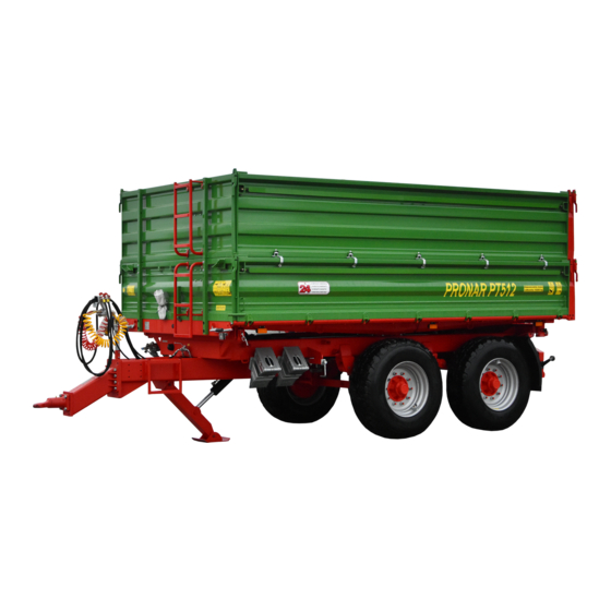
PRONAR PT512
TRANSLATION OF THE ORIGINAL DOCUMENT
+48 085 681 63 29
+48 085 681 63 81
+48 085 681 63 83
TRAILER
PUBLICATION NO. 327N-00000000-UM
+48 085 681 64 29
+48 085 681 63 82
+48 085 682 71 10
www.pronar.pl
Advertisement
Table of Contents

Subscribe to Our Youtube Channel
Related Manuals for PRONAR PT512


Summary of Contents for PRONAR PT512
- Page 1 PRONAR Sp. z o.o. 17-210 NAREW, UL. MICKIEWICZA 101A, WOJ. PODLASKIE, POLAND Phone.: +48 085 681 63 29 +48 085 681 64 29 +48 085 681 63 81 +48 085 681 63 82 Fax: +48 085 681 63 83 +48 085 682 71 10 www.pronar.pl...
- Page 3 The machine is designed to meet obligatory standards, documents and legal regulations currently in force. The manual describes the basic safety and operation rules of Pronar PT512 trailer. If the information contained in the Operator's Manual needs clarification, the user should refer for assistance to the sale point where the machine was purchased or to the manufacturer.
- Page 4 SYMBOLS USED IN THIS MANUAL Information, descriptions of danger, precautions, recommendations and orders associated with user safety instructions are indicated as follows: and preceded by the word "DANGER". Failure to observe the instructions may endanger the machine operator's or other person's health or life. Particularly important information and instructions, the observance of which is essential, are indicated with the sign: and preceded by the word "ATTENTION".
- Page 5 DETERMINING THE DIRECTIONS FOR THE MANUAL'S NEEDS Left side — a left hand side of the person facing the machine's forward travel direction. Right side — a right hand side of the person facing the machine's forward travel direction. SCOPE OF OPERATION STEPS Operation steps are indicated with the following sign: The result of an operation/adjustment task or any notes on execution of the tasks performed is indicated with the sign...
-
Page 7: Table Of Contents
TABLE OF CONTENTS GENERAL INFORMATION 1.1 IDENTIFICATION 1.1.1 IDENTIFICATION OF THE TRAILER 1.1.2 IDENTIFICATION OF THE AXLES 1.1.3 LIST OF SERIAL NUMBERS 1.2 APPLICATION 1.3 EQUIPMENT 1.4 WARRANTY TERMS 1.10 1.5 TRANSPORT 1.12 1.5.1 TRANSPORT ON A VEHICLE. 1.12 1.5.2 INDEPENDENT TRANSPORT BY THE USER. - Page 8 DESIGN AND OPERATION 3.1 TECHNICAL SPECIFICATION 3.2 TRAILER CONSTRUCTION 3.2.1 CHASSIS 3.2.2 LOADING CASE 3.2.3 THE MAIN BRAKE 3.2.4 HYDRAULIC TIPPING SYSTEM 3.14 3.2.5 SUPPORT HYDRAULIC SYSTEM 3.16 3.2.6 PARKING BRAKE 3.17 3.2.7 LIGHTING SYSTEM 3.18 CORRECT USE 4.1 PREPARING FOR WORK BEFORE THE FIRST USE 4.1.1 CHECKING THE TRAILER AFTER DELIVERY 4.1.2...
- Page 9 5.2.3 INSPECTION OF AXLE BEARINGS PLAY 5.2.4 ADJUSTMENT OF AXLE BEARINGS PLAY 5.2.5 MOUNTING AND DISMOUNTING THE WHEEL, INSPECTION OF WHEEL TIGHTENING 5.2.6 CONTROL OF AIR PRESSURE, EVALUATING TECHNICAL CONDITION OF TIRES AND STEEL WHEELS 5.2.7 ADJUSTMENT OF MECHANICAL BRAKES 5.10 5.2.8 REPLACEMENT OF PARKING BRAKE CABLE AND ADJUSTMENT OF...
- Page 10 5.7.1 HYDRAULIC OIL 5.32 5.7.2 LUBRICANTS 5.33 5.8 CLEANING THE TRAILER 5.33 5.9 STORAGE 5.35 5.10 TORQUE VALUES FOR BOLTED JOINTS 5.35 5.11 INSTALLATION AND DISASSEMBLY OF EXTENSIONS 5.37 5.12 ADJUSTMENT OF DRAWBAR POSITION 5.37 5.13 TROUBLESHOOTING 5.39...
-
Page 11: General Information
CHAPTER GENERAL INFORMATION... -
Page 12: Identification
Pronar PT512 CHAPTER 1 1.1 IDENTIFICATION 1.1.1 IDENTIFICATION OF THE TRAILER FIGURE 1.1 Location of the rating plate and the serial number (1) rating plate, (2) serial number The trailer has been identified by means of a rating plate (1) and a serial number (2) stamped on a rectangular, gold-painted area. -
Page 13: Identification Of The Axles
CHAPTER 1 Pronar PT512 When buying the trailer, check that the serial numbers on the machine agree with the number written in the WARRANTY BOOK, in the sales documents and the OPERATOR'S MANUAL. The meaning of particular fields of the rating plate is presented in the table below. -
Page 14: List Of Serial Numbers
Pronar PT512 CHAPTER 1 FIGURE 1.2 Location of the axle rating plate (1) axle, (2) rating plate 1.1.3 LIST OF SERIAL NUMBERS FRONT AXLE SERIAL NUMBER REAR AXLE SERIAL NUMBER In case spare parts must be ordered or in case of problems, it may be required to provide serial numbers of particular components or the trailer's VIN. - Page 15 CHAPTER 1 Pronar PT512 following the manufacturer's recommendations relating to the transport and loading, as well as the traffic regulations of the country the trailer is used in will render the warranty void and will be treated as misuse of the machine.
- Page 16 Pronar PT512 CHAPTER 1 • understand the principle of operation of the machine and its safe and proper use, • follow the maintenance and adjustment intervals, • follow general safety regulations, • prevent accidents, • follow the traffic and transport regulations of the country in which the trailer is used, •...
- Page 17 CHAPTER 1 Pronar PT512 ITEM UNIT REQUIREMENTS Braking system – sockets Pneumatic, single-line acc. to A DIN 74294 Pneumatic, twin-line acc. to A DIN 74294 Hydraulic acc. to ISO 7421-1 System pressure Pneumatic, single-line bar/kPa 5.8 – 6.5 / 580 - 650...
- Page 18 Pronar PT512 CHAPTER 1 TABLE 1.4 Requirements on the second trailer ITEM UNIT REQUIREMENTS Allowable total weight Two-axle trailer 16 500 Braking system – connectors Pneumatic, single-line connector acc. to A DIN 74294 Pneumatic, twin-line connector acc. to A DIN 74294 Hydraulic connector acc.
-
Page 19: Equipment
CHAPTER 1 Pronar PT512 1.3 EQUIPMENT TABLE 1.5 Trailer equipment list EQUIPMENT • Operator's Manual • Warranty Book • Electrical system cable • Single- and twin-line pneumatic system • Twin-line pneumatic system with an automatic regulator • Hydraulic braking system •... -
Page 20: Warranty Terms
Information on tires are presented at the end of this document – see ANNEX A. 1.4 WARRANTY TERMS PRONAR Sp. z o.o. Narew guarantees the reliable operation of the machine when it is used according to technical and operation conditions described in the OPERATOR'S MANUAL. - Page 21 CHAPTER 1 Pronar PT512 • bulbs and LED lamps, • seals, • bearings. The warranty service applies only to such cases as: mechanical damage which is not the user's fault, factory defects of parts, etc. In the event of damage arising from: •...
-
Page 22: Transport
Pronar PT512 CHAPTER 1 1.5 TRANSPORT The trailers are sold completely assembled and do not require packing. Only the machine's technical documentation and extra equipment are packed. The trailer can be delivered to the user either on a vehicle or independently (trailer towed with a tractor). - Page 23 CHAPTER 1 Pronar PT512 FIGURE 1.3 Location of transport lugs (1) transport lug, (2) upper frame longitudinal member, (3) lower frame longitudinal member ATTENTION If the trailer is transported on a vehicle, it must be secured on the transport vehicle's platform according to relevant safety requirements and regulations.
-
Page 24: Independent Transport By The User
Pronar PT512 CHAPTER 1 1.5.2 INDEPENDENT TRANSPORT BY THE USER. If the trailer is transported independently, the user must read the trailer Operator's Manual and adhere to the recommendations contained therein. Independent transport involves towing the trailer with a tractor. During transport adjust the travel speed to the prevailing road conditions and do not exceed the trailer's maximum design speed. -
Page 25: Withdrawal From Use
CHAPTER 1 Pronar PT512 appropriate facility recycling or regenerating this type of waste. Waste code: 13 01 10. Detailed information concerning hydraulic oil may be found on the product's Material Safety Data Sheet. The hydraulic system of the trailer is filled with L-HL32 Lotos hydraulic oil. - Page 26 Pronar PT512 CHAPTER 1 1.16...
-
Page 27: Safety Of Operation
CHAPTER SAFETY OF OPERATION... -
Page 28: General Safety Rules
Pronar PT512 CHAPTER 2 2.1 GENERAL SAFETY RULES 2.1.1 USE OF THE TRAILER • Before operating the trailer, carefully read this Operator's Manual and the WARRANTY BOOK. When operating the machine, the operator must comply with the recommendations stated in these documents. -
Page 29: Hitching And Disconnecting From Tractor
CHAPTER 2 Pronar PT512 • The user of the trailer is obliged to familiarize oneself with the construction, operation principle and rules of safe operation of the trailer. 2.1.2 HITCHING AND DISCONNECTING FROM TRACTOR • Do not hitch the trailer to a tractor not fulfilling the requirements stated by the manufacturer (minimal tractor power requirement, inappropriate hitch etc.) –... -
Page 30: Hydraulic And Pneumatic Systems
Pronar PT512 CHAPTER 2 • Only double axle trailers having the maximum allowable weight given in table (1.3) can be coupled to the trailer. • Before hitching the trailer to a tractor check that the tractor and the trailer are in good technical condition. -
Page 31: Loading And Unloading The Trailer
CHAPTER 2 Pronar PT512 occurs, consult a doctor. In the event of contact of oil with skin, wash the area of contact with water and soap. Do not apply organic solvents (petrol, kerosene). • Use the hydraulic oil recommended by the manufacturer. - Page 32 • Bulk materials loaded in the trailer with the second set of extensions must be unloaded with particular care. • When operating Pronar PT512 trailer with the second set of extension installed, the risk of occurrence of following hazards is more significant: losing the trailer's...
-
Page 33: Transport Run
CHAPTER 2 Pronar PT512 • During winter pay particular attention to materials which may freeze during transport. When tipping the loading case with frozen load the trailer may become unstable and tip over. • Do not raise the loading case if there is any danger whatsoever that the case will tip over. - Page 34 Pronar PT512 CHAPTER 2 FIGURE 2.1 Method of placing wheel chocks (1) wheel chock • The wheel chocks (1) must be placed only under one wheel (one in the front of the wheel, the second behind the wheel • Do not leave the trailer unattended. The trailed disconnected from a tractor must be secured against rolling by means of the parking brake and the wheel chocks or other objects without sharp edges laid under the wheels of the vehicle.
- Page 35 CHAPTER 2 Pronar PT512 • Each time before using the trailer always check its technical condition, especially in terms of safety. In particular, check the technical condition of the hitch system, the axle system, the brake system, lights and the connections of the hydraulic, pneumatic and electrical systems.
-
Page 36: Tires
Pronar PT512 CHAPTER 2 • While driving on public roads, an approved reflective warning triangle must be available as the trailer's and a tractor's equipment. • Periodically drain water from the air tank of the pneumatic system. Freezing water may cause damage to pneumatic system components. -
Page 37: Maintenance
CHAPTER 2 Pronar PT512 • Check the tightening of the nuts after first operation of the trailer, after the first driving with load and then once per 6 months of operation or 25,000 kilometers. In the event of intensive work checking the nut tightening should be done at least every 100 km. - Page 38 Pronar PT512 CHAPTER 2 • Before beginning works requiring raising the loading case, it must be emptied and secured by a support to prevent accidental falling. At this time the trailer must be hitched to the tractor and secured with chocks and the parking brake.
-
Page 39: Residual Risk Assessment
2.2 RESIDUAL RISK ASSESSMENT Pronar Sp. z o. o. with its premises in Narew has made every effort to eliminate the risk of accidents. There is however certain residual risk which could lead to an accident; this is connected mainly with the actions described below: •... -
Page 40: Information And Warning Decals
Pronar PT512 CHAPTER 2 • being between a tractor and the trailer while the tractor's engine is working and when the machine is being attached or hitched to the second trailer, • being on the machine during its operation, • not maintaining safe distance during loading or unloading of the trailer, •... - Page 41 CHAPTER 2 Pronar PT512 Damaged decals are to be replaced. Safety decals are available from the manufacturer or your local dealer. New assemblies, replaced during repairs, must be relabeled with an appropriate safety signs. When cleaning the trailer, do not use solvents, as they can damage the coating of information decals.
- Page 42 Pronar PT512 CHAPTER 2 ITEM DECAL MEANING Before climbing onto the trailer, switch off tractor's engine and remove key from ignition. Note. Danger of electric shock. Keep a safe distance from overhead power lines during unloading. Danger of crushing. Do not perform any...
- Page 43 CHAPTER 2 Pronar PT512 ITEM DECAL MEANING Grease the trailer according to the recommendations of the Operator's Manual. Hose supplying hydraulic braking system. Hose supplying hydraulic tipping system. Information on typical weight of selected material types. Positions of control valve controlling the operation of hydraulic tipping system.
- Page 44 Pronar PT512 CHAPTER 2 ITEM DECAL MEANING Positions of control valve controlling the operation of hydraulic support. Hose supplying the scissor support's hydraulics. Return line of the scissor support's hydraulics. Quality control decal. Allowable total weight. – pressure value should be adapted to tires Numbers in the "ITEM"...
- Page 45 CHAPTER 2 Pronar PT512 FIGURE 2.3 Locations of information and warning decals 2.19...
- Page 46 Pronar PT512 CHAPTER 2 2.20...
-
Page 47: Design And Operation
CHAPTER DESIGN AND OPERATION... -
Page 48: Technical Specification
Pronar PT512 CHAPTER 3 3.1 TECHNICAL SPECIFICATION TABLE 3.1 Basic technical data ITEM UNIT PT512 Dimensions Total length 6 139 Total width 2 550 Total height 2 652 Internal loading case dimensions Length: 4 544 Width: 2 416 Height 600 + 800... -
Page 49: Trailer Construction
CHAPTER 3 Pronar PT512 3.2 TRAILER CONSTRUCTION 3.2.1 CHASSIS Trailer chassis consists of assemblies indicated on figure (3.1). The lower frame (1) of the loading case is welded from steel sections. The lower frame construction depends on the version of a trailer. The main support elements are two longitudinal members connected with crossbars. - Page 50 Pronar PT512 CHAPTER 3 FIGURE 3.1 Chassis (1) lower frame, (2) tipping cylinder bracket, (3) lights support beam, (4) axle, (5) wheel, (6) drawbar, (7) rear beam, (8) front crossbar, (9) loading case support, (10) trailer support, (11) fender, (12) wheel chocks, (13) brake mechanism, (14) wire harness support,...
-
Page 51: Loading Case
(2), the front wall (3) and the rear wall (4). The side walls are 600 mm high. As standard, Pronar PT512 trailer is also equipped with profiled extensions having the height of 800 mm. Optionally additional 600 mm extensions can be fitted (only in 600 + 600 + 600 version). - Page 52 Pronar PT512 CHAPTER 3 FIGURE 3.2 Loading case – view from the rear (1) upper frame, (2) side wall, (3) front wall, (4) rear wall, (5) wall rear pillar, (6) lever, (7) extension rear pillar, (8) hinge, (9) front extension, (10) side extension, (11) rear extension Access ladders (2) and (3) are attached to the front wall and extension.
- Page 53 CHAPTER 3 Pronar PT512 FIGURE 3.3 Loading case – view from the front (1) side wall closing lever, (2) lower ladder, (3) extension ladder, (4) platform, (5) canvas cover, (6) pull-off springs In order to enable more precise unloading of loose materials there is a slide gate (1) in the rear wall –...
-
Page 54: The Main Brake
Pronar PT512 CHAPTER 3 FIGURE 3.4 Rear wall slide gate (1) slide gate, (2) lever, (3) locking bolt 3.2.3 THE MAIN BRAKE The trailer can be equipped with one of three of main brake types: • a single- or twin-line pneumatic braking system with three position manual regulator –... - Page 55 CHAPTER 3 Pronar PT512 FIGURE 3.5 A single- and twin-line pneumatic braking system with a manual braking force regulator (1) air reservoir, (2) control valve, (3) braking force regulator, (4) pneumatic cylinder, (5) line connector (yellow), (6) line connector (red), (7) air filter, (8) air reservoir control connector,...
- Page 56 Pronar PT512 CHAPTER 3 FIGURE 3.6 A twin-line pneumatic braking system with an automatic braking force regulator (1) air reservoir, (2) control valve, (3) braking force regulator, (4) pneumatic cylinder, (5) line connector (yellow), (6) line connector (red), (7) air filter, (8) air reservoir control connector,...
- Page 57 CHAPTER 3 Pronar PT512 The main pneumatic brake is activated from the tractor driver's cab by pressing the brake pedal. The function of a control valve (2) – figures (3.5) and (3.6) – is to operate the trailer brakes simultaneously with the tractor brakes. Furthermore, in case of an incidental disconnection of the line between the trailer and a tractor, the control valve will automatically activate the trailer's brake.
- Page 58 Pronar PT512 CHAPTER 3 FIGURE 3.8 A single-line hydraulic braking system (1) electro-hydraulic valve, (2) hydraulic cylinder, (3) hydraulic quick coupling, (4) hydraulic accumulator, (5) socket, (6) valve connector cable, (7) information decal The main hydraulic brake (available optionally) is activated from the tractor driver's cab by pressing the brake pedal.
- Page 59 CHAPTER 3 Pronar PT512 trailer's brake. The same effect of emergency braking is achieved when the engine is turned off and during the loss of voltage on the solenoid. FIGURE 3.9 Electro-hydraulic brake valve (1) electro-hydraulic valve, (2) valve working mode selection lever, (3) release button, (4) electric coil, (A) position "NO LOAD”, (B) position "HALF LOADED”, (C) position "FULL...
-
Page 60: Hydraulic Tipping System
Pronar PT512 CHAPTER 3 cable and the supply hose are connected and when the voltage in supplied to the control valve. The electro-hydraulic brake valve (1) – see figure (3.9) – adjusts the braking force depending on the setting. Switching to a suitable working mode is done manually by the operator before driving off, by means of the lever (2). - Page 61 CHAPTER 3 Pronar PT512 FIGURE 3.10 Hydraulic tipping system (1) telescopic cylinder, (2) three-way valve, (3) cut-off valve, (4) quick coupling, (5) socket, (6) control cable, (7) guide roller, (8), (9) information decals The trailer's hydraulic system is filled with L-HL32 Lotos hydraulic oil.
-
Page 62: Support Hydraulic System
Pronar PT512 CHAPTER 3 3.2.5 SUPPORT HYDRAULIC SYSTEM The support hydraulic system – figure (3.11) – allows to automatically extend and fold the support (3). This is achieved by extending or retracting the hydraulic cylinder's rod (4). The oil is supplied to the support hydraulic system from the tractor's system by means of a line (1). -
Page 63: Parking Brake
CHAPTER 3 Pronar PT512 When the support is being raised or lowered, the system's lines can become damaged, resulting in depressurization. In such case the hydraulic locking device will lock the cylinder (4) in a given position. The support's hydraulic system is filled with L-HL32 Lotos hydraulic oil. -
Page 64: Lighting System
Pronar PT512 CHAPTER 3 Steel cable (2), guided by means of roller (3), is attached to axle expander arms and the brake crank mechanism (1). Tensioning the cable causes the expander arms to tilt; the brake shoes are opened and the trailer is immobilized. - Page 65 CHAPTER 3 Pronar PT512 TABLE 3.2 List of electrical system components designations DESIGNATION FUNCTION Rear right lamp assembly Rear left lamp assembly Front 7-pin socket Rear 7-pin socket Right license plate light Left license plate light Front right position light...
- Page 66 Pronar PT512 CHAPTER 3 FIGURE 3.14 Locations of electrical system components and reflective lights – rear view (1) rear left lamp assembly, (2) rear right lamp assembly, (3) license plate light, (4) rear 7-pin socket, (5) Rear right clearance light, (6) rear left clearance light, (7) side position light...
- Page 67 CHAPTER 3 Pronar PT512 FIGURE 3.15 Locations of electrical system components and reflective lights – front view (1) front position light, (2) front 7-pin socket, (3) side position light, (4) connector cable 3.21...
- Page 68 Pronar PT512 CHAPTER 3 3.22...
-
Page 69: Correct Use
CHAPTER CORRECT... -
Page 70: Preparing For Work Before The First Use
Pronar PT512 CHAPTER 4 4.1 PREPARING FOR WORK BEFORE THE FIRST USE 4.1.1 CHECKING THE TRAILER AFTER DELIVERY The manufacturer guarantees that the trailer is fully operational and has been checked according to quality control procedures and is ready for normal use. This does not free the user from an obligation to check the machine's condition after delivery and before the first use. - Page 71 CHAPTER 4 Pronar PT512 Check all the trailer's lubrication points; if necessary, lubricate the machine as needed according to recommendations provided in chapter 5. Check if the nuts and bolts fixing the wheels and drawbar are properly tightened. Drain the air reservoir of the braking system.
-
Page 72: Hitching And Disconnecting From Tractor
Pronar PT512 CHAPTER 4 The trailer can be hitched only when all preparations were finished and if the visual inspection of its technical condition was carried out. If during the test run the following symptoms occur: • noise and abnormal sounds originating from the abrasion of moving elements of the trailer's structure, •... - Page 73 CHAPTER 4 Pronar PT512 Hitching Immobilize the trailer with the parking brake. Rotate the brake mechanism clockwise to release the brake. Position a tractor directly in front of drawbar eye. Connect the scissor support's hydraulic lines. The scissor support's hydraulic lines are indicated by means of information decals (4) and (5) –...
- Page 74 Pronar PT512 CHAPTER 4 If the tractor is equipped with an automatic coupling, ensure that the hitching operation is completed and that drawbar eye is secured. Turn off the engine. Close the tractor cab and secure it against access by unauthorized persons.
- Page 75 CHAPTER 4 Pronar PT512 the tractor and only then connect the red connector to the red socket of the tractor. Once the 2nd line is connected, the brake releasing system will switch to normal mode of operation (disconnection or breaking of the pneumatic lines causes the trailer's control valve to automatically apply brakes).
- Page 76 Pronar PT512 CHAPTER 4 Turn off the engine. Close the tractor cab and secure it against access by unauthorized persons. Disconnect hydraulic tipping system lines from the tractor. Disconnect the electric cable. Disconnect the pneumatic system lines (applies to twin-line pneumatic systems).
-
Page 77: Coupling And Uncoupling The Second Trailer
CHAPTER 4 Pronar PT512 ATTENTION Do not park a loaded trailer if it is disconnected from the tractor and supported by means of the support. 4.3 COUPLING AND UNCOUPLING THE SECOND TRAILER The second trailer must have a dual axle chassis and fulfill all the requirements specified in chapter 1. -
Page 78: Loading And Securing The Load
Pronar PT512 CHAPTER 4 Remove the cotter pin and remove the hitch pin (2) from the first trailer – figure (4.2). Adjust the height of the drawbar of the second trailer to enable coupling the machines. By reversing the tractor, insert the rear hitch of the first trailer onto the drawbar of the second trailer Insert the pin and the cotter pin. -
Page 79: General Information On The Loading
CHAPTER 4 Pronar PT512 Securing the load by means of a canvas cover When standing on the front platform, start unfolding the cover (2) by means of a crank (1). Pass all tensioning straps (4) through clamps (3) located on the trailer's loading case. - Page 80 Pronar PT512 CHAPTER 4 Materials which can come in contact with painted or steel surfaces and damage them, should be transported in sealed packaging (sacks, boxes, barrels etc.); after completing the transport, thoroughly wash the loading case with strong water jet.
- Page 81 CHAPTER 4 Pronar PT512 VOLUMETRIC WEIGHT TYPE OF MATERIAL kg/m Mineral fertilizers: ammonium sulphate 800 - 850 potash salt 1 100 – 1 200 super phosphate 850 – 1 440 basic slag phosphate 2 000 – 2 300 potassium sulphate 1 200 –...
- Page 82 Pronar PT512 CHAPTER 4 VOLUMETRIC WEIGHT TYPE OF MATERIAL kg/m clover (lucerne) cut wilted on trailer 110 - 160 clover (lucerne) wilted on gathering trailer 60 - 100 dry stored clover 40 - 60 cut dry stored clover 80 - 140...
- Page 83 CHAPTER 4 Pronar PT512 VOLUMETRIC WEIGHT TYPE OF MATERIAL kg/m bone meal 700 – 1 000 pasture salt 1 100 – 1 200 molasses 1 350 – 1 450 silage (pit silo) 650 – 1 050 hay silage (tower silo)
- Page 84 Pronar PT512 CHAPTER 4 NOTE The trailer is designed for transporting agricultural commodities (volumetric or loose loads) and goods on europallets or collar pallets. It is permissible to transport other loads (timber, building materials, packed loads) if the loading case is properly protected against damage.
- Page 85 CHAPTER 4 Pronar PT512 height. The material must not fall on the loading case floor with great force, even if the floor has been covered. Hazardous materials According to the European ADR agreement concerning international road transport of hazardous materials, transporting this type of load (defined in detailed by this agreement) by means of agricultural trailers is prohibited.
- Page 86 Pronar PT512 CHAPTER 4 of load securing points), materials in packaging may not be loaded above the top of the walls or extensions of the loading case. The top layer may move during travel. DANGER If there is a danger that the packaged goods will move, do not transport this type of loads.
-
Page 87: Transporting Loads
CHAPTER 4 Pronar PT512 4.5 TRANSPORTING LOADS When driving on public or private roads, respect the road traffic regulations, exercise caution and behave reasonably. Listed below are the key guidelines for driving the tractor with a trailer hitched. • Before driving off make sure that there are no bystanders, especially children, near the trailer or the tractor. -
Page 88: Unloading
Pronar PT512 CHAPTER 4 • When driving, comply with all road traffic regulations, indicate an intention to turn by means of directional indicators, keep all lights and indicator lights clean at all times and ensure they are in good condition. Any damaged or missing lamps or indicator lights must be immediately repaired or replaced. - Page 89 CHAPTER 4 Pronar PT512 The trailer is unloaded in the following sequence: the tractor and the trailer must be parked to drive forwards on a flat and hard ground, FIGURE 4.4 Securing the tipping pins (1) tipping pin I, (2) tipping pin II, (3) tipping pin handle immobilize the tractor and the trailer with the parking brake;...
- Page 90 Pronar PT512 CHAPTER 4 if the tipping direction has not been planned and set, position the tipping pins (1) and (2) at the side on which the load will be unloaded and secure them – see figure (4.4), the tipping pins and the sockets are designed so it is impossible to...
- Page 91 CHAPTER 4 Pronar PT512 FIGURE 4.5 Wall and extension locks (1) left side wall closing lever (2), rear wall closing lever (3) side wall lock (left, rear), (4) rear wall lock (left), (5) extension lug DANGER Improperly secured tipping pins can cause severe damage to the trailer.
- Page 92 Pronar PT512 CHAPTER 4 FIGURE 4.6 Chute (1) slide gate, (2) chute, (3) lever, (4) locking bolt The rear wall of the loading case is equipped with a slide gate (1) – figure (4.6) – and the chute (2) (optional equipment) which is used for unloading loose materials. The chute design allows for very accurate metering of the material to packaging (sacks, boxes etc).
-
Page 93: Proper Use And Maintenance Of Tyres
CHAPTER 4 Pronar PT512 difficult to unload therefore proceed cautiously and patiently. Careless operation of the trailer may pose a danger to operators and bystanders can also cause damage to the machine. ATTENTION It is not recommended to unload the loading case by opening the walls downwards (with the loading case lower locks bolted). -
Page 94: Operating The Under Run Protective Device
Pronar PT512 CHAPTER 4 • Check the tightening of the nuts after first operation of the trailer, after the first driving with load and then once per 6 months of operation or 25,000 kilometers. In the event of intensive work checking the nut tightening should be done at least every 100 km. - Page 95 CHAPTER 4 Pronar PT512 FIGURE 4.7 Left under run protective device (1) left under run protective device, (2) barrier handle bracket, (3) clamp, (4) catch, (5) lock bolt Lowering • Pull the under run protective device. • Lower the device and push it so that the bracket pin locks in place.
- Page 96 Pronar PT512 CHAPTER 4 • Secure the devices by means of pins (5). DANGER It is prohibited to drive with the under run protective device raised. Before driving off make sure, that the under run protective devices are lowered and locked in place.
-
Page 97: Maintenance
CHAPTER MAINTENANCE... -
Page 98: Preliminary Information
Pronar PT512 CHAPTER 5 5.1 PRELIMINARY INFORMATION When using the trailer, regular inspections of its technical condition are essential, as well as performance of maintenance procedures which keep the machine in good technical condition. Therefore, the user is obliged to perform all maintenance and adjustment procedures defined by the manufacturer. -
Page 99: Initial Inspection Of Axle Brakes
CHAPTER 5 Pronar PT512 may be performed by specialist workshops. DANGER Do not use the trailer when brake system is unreliable. 5.2.2 INITIAL INSPECTION OF AXLE BRAKES After purchasing the trailer, the user is responsible for general checking of brake system of trailer axle. -
Page 100: Inspection Of Axle Bearings Play
Pronar PT512 CHAPTER 5 5.2.3 INSPECTION OF AXLE BEARINGS PLAY FIGURE 5.1 Lifting jack support point (1) drive axle, (2) U bolt, (3) lower frame Preparation procedures Hitch the trailer to a tractor; immobilize the tractor with the parking brake. - Page 101 CHAPTER 5 Pronar PT512 Inspection of axle bearings play Turning the wheel slowly in both directions, check that movement is smooth and that the wheel rotates without excessive resistance and blockages. Turn the wheel so that it rotates very quickly and check if the bearing does not make any unusual sounds.
-
Page 102: Adjustment Of Axle Bearings Play
Pronar PT512 CHAPTER 5 Check the technical condition of hub cover, if necessary replace with new one. Inspection of bearing play may only be conducted, when the trailer is hitched to a tractor, and the loading case is empty. 5.2.4... -
Page 103: Mounting And Dismounting The Wheel, Inspection Of Wheel Tightening
CHAPTER 5 Pronar PT512 Unscrew nut (not less than 1/3 rotation) to cover the nearest thread groove with alignment to opening in wheel stub axle. Wheel should rotate without excessive resistance. Wheel should rotate with insignificant resistance. Do not apply excessive pressure with regard for deterioration of bearing working conditions. - Page 104 Pronar PT512 CHAPTER 5 Do not grease thread of nuts and pins. Check the technical condition of pins and nuts, replace if necessary. Place the wheel on hub, tighten nuts so that wheel rim is exactly fitted on the hub.
-
Page 105: Control Of Air Pressure, Evaluating Technical Condition Of Tires And Steel Wheels
CHAPTER 5 Pronar PT512 Checking the tightening of axle wheels: • after first use, • after first travel with load, • after first 1000 km, • per 6 months of operation or 25,000 kilometers. In the event of intensive work checking the nut tightening should be done at least every 10,000 km. -
Page 106: Adjustment Of Mechanical Brakes
Pronar PT512 CHAPTER 5 Tire pressure values are specified on information decal which is placed on wheel or on upper frame above the trailer wheel. DANGER Damaged tires or wheels may cause the serious accident. While checking the pressure, pay attention to technical condition of wheels and tires. Look carefully at tire sides and check the condition of tread. - Page 107 CHAPTER 5 Pronar PT512 Trailer wheels must brake simultaneously. Adjustment of brakes involves changing the setting of the expander arm (1) – figure 5.4), in relation to expander shaft (2). Scope of maintenance Dismantle the pin (3) fixing the cylinder fork (4) to expander arm (3).
-
Page 108: Replacement Of Parking Brake Cable And Adjustment Of Cable Tension
Pronar PT512 CHAPTER 5 Adjustment should be conducted separately for each wheel. Expander arm (1) should be moved by one notch in the selected direction. If the extent of cylinder action is still incorrect, move the lever again. After proper brake adjustment, at full braking the axle shaft expander... - Page 109 CHAPTER 5 Pronar PT512 FIGURE 5.5 Adjustment of parking brake cable tension (1) brake crank mechanism, (2) U-shaped clamp, (3) handbrake cable, (4) guiding roll, (5) expander arm Lubricate the parking brake mechanism (1), and pins of cable guiding wheels rolls (4).
- Page 110 Pronar PT512 CHAPTER 5 Insert pins and new cotter pins. Adjust the tension of parking brake cable. After first engagement of the brake, check if cable tension is correct. Adjust if necessary. FIGURE 5.6 Mounting the brake cable clamps Adjustment of parking brake cable tension Hitch the trailer to a tractor.
-
Page 111: Maintenance Of Pneumatic System
CHAPTER 5 Pronar PT512 Inspection and/or adjustment of parking brake should be done: • every 12 months, • if needed. 5.3 MAINTENANCE OF PNEUMATIC SYSTEM 5.3.1 PRELIMINARY INFORMATION Works connected with the repair, change or regeneration of system components (brake cylinders, hoses, control valve braking force regulator etc.) should be entrusted to specialist... - Page 112 Pronar PT512 CHAPTER 5 In single-line systems air pressure should be in range of 5.8 – 6.5 bar. In twin-line systems air pressure should be approx. 6.5 bar. Turn off the engine. Release the brake pedal in a tractor and check the system components.
-
Page 113: Cleaning The Air Filters
CHAPTER 5 Pronar PT512 ATTENTION Repair, replacement or regeneration of pneumatic system components may only be performed in a specialized workshop. 5.3.3 CLEANING THE AIR FILTERS Depending on trailer working conditions, but not less than once in three months, remove and clean air filter elements which are located on pneumatic system connection lines. -
Page 114: Draining Water From The Air Reservoir
Pronar PT512 CHAPTER 5 Reduction of pressure may be achieved by pressing the head of the pneumatic connector until the resistance is felt. Remove the sliding lock (1) – figure (5.6). Hold the filter cover (2) with other hand. After removing sliding lock, the cover is pushed off by the spring in the filter housing. -
Page 115: Cleaning The Drain Valve
CHAPTER 5 Pronar PT512 Scope of maintenance Tilt out drain valve stem (1) placed in lower part of the tank (2) – the tank is placed on brackets of right longitudinal of lower frame. The compressed air in the tank will cause the removal of water to the exterior. -
Page 116: Cleaning And Maintenance Of Pneumatic Sockets And Line Connectors
Pronar PT512 CHAPTER 5 Clean the tank: • every 12 months (before winter season). 5.3.6 CLEANING AND MAINTENANCE OF PNEUMATIC SOCKETS AND LINE CONNECTORS DANGER Unreliable and dirty trailer connectors may cause faulty functioning of braking system. Damaged connector body or sockets for connecting the second trailer should be replaced. In case of damage to cover or seal, change these elements with new reliable ones. - Page 117 CHAPTER 5 Pronar PT512 Dismount the spiral line (yellow) (5) with line connector. Uninstall the air filter (6). FIGURE 5.9 Altering the twin-line pneumatic system into single-line pneumatic system (1) control valve, (2) relay valve, (3) air reservoir, (4) water drain valve, (5) spiral line (yellow),...
-
Page 118: Replacement Of Pneumatic Line
Pronar PT512 CHAPTER 5 Uninstall Tekalan lines and all connectors from control valve (1) and relay valve (2). Screw appropriate plugs (7) and (8) in place of dismounted connectors in control valve (1) and relay valve (2). Valve sockets to which plugs should be screwed are designed by number 4. -
Page 119: Maintenance Of Hydraulic System
CHAPTER 5 Pronar PT512 FIGURE 5.10 Construction of pneumatic line (1) pneumatic line, (2) connecting nut, (3) cutting ring, (4) reinforcing sleeve 5.4 MAINTENANCE OF HYDRAULIC SYSTEM 5.4.1 PRELIMINARY INFORMATION DANGER Do not tip the trailer with unreliable hydraulic tipping system. -
Page 120: Control Of Hydraulic System Tightness
Pronar PT512 CHAPTER 5 User is obliged to perform only the following maintenance work on the hydraulic system: • visual inspection and control of system tightness, • inspection of the technical condition of hydraulic connectors. 5.4.2 CONTROL OF HYDRAULIC SYSTEM TIGHTNESS Scope of maintenance Hitch the trailer to a tractor. -
Page 121: Replacement Of Hydraulic Lines
CHAPTER 5 Pronar PT512 sensitive to the presence of solid contamination which may cause damage to precision components of the system (contamination may cause blockages in hydraulic valves, abrasion of cylinder surfaces etc.) Check hydraulic connectors and sockets: • every time when the trailer is to be hitched to a tractor or when the second trailer is to be connected. -
Page 122: Replacement Of Bulbs
Pronar PT512 CHAPTER 5 • replacement of bulbs. Scope of maintenance Connect the trailer to a tractor with the correct connecting cable. Check if the connecting cable is reliable. Check connecting sockets in the trailer and a tractor. Check completeness, technical condition and reliability of trailer's lights. -
Page 123: Trailer Lubrication
CHAPTER 5 Pronar PT512 5.6 TRAILER LUBRICATION Trailer lubrication should be performed by means of manually or foot operated grease gun filled with recommended grease. Before commencing lubrication remove old grease and other contamination as far as possible. After finishing remove excess of grease. - Page 124 Pronar PT512 CHAPTER 5 ITEM LUBRICATION POINT Ball bearing of tipping cylinder Parking brake mechanism Pins of parking brake guiding rollers Articulated joints and sockets for installation of loading case Side extension lugs Sliding ramp guides Pins of sliding ramp links...
- Page 125 CHAPTER 5 Pronar PT512 ITEM LUBRICATION POINT Pin of side guy ropes mechanism Locking lever of side walls lubrication periods: M – month, D – day – not shown on the figure FIGURE 5.13 Recommended lubricants MARKING FROM TAB. DESCRIPTION (5.4)
- Page 126 Pronar PT512 CHAPTER 5 FIGURE 5.11 Trailer lubrication points, part 1 5.30...
- Page 127 CHAPTER 5 Pronar PT512 FIGURE 5.12 Trailer lubrication points, part 2 5.31...
-
Page 128: Consumables
Pronar PT512 CHAPTER 5 5.7 CONSUMABLES 5.7.1 HYDRAULIC OIL Always adhere to the principle that the oil in the trailer hydraulic system and in the tractor hydraulic system are of the same type. If oil of different types is used be sure that both hydraulic substances may be mixed together. -
Page 129: Lubricants
CHAPTER 5 Pronar PT512 5.7.2 LUBRICANTS For parts under heavy load it is recommended to apply lithium grease with molybdenum disulphide (MOS ) or graphite additive. In the case of less loaded sub-assemblies the application of general purpose machine greases is recommended which contain anticorrosion additive and have significant resistance to being washed away by water. - Page 130 Pronar PT512 CHAPTER 5 and trailer lubrication points etc. Too high pressure of water may cause mechanical damage to these elements. • For cleaning and maintenance purposes of plastic surfaces it is recommended to use clean water or special compounds designed for this purpose.
-
Page 131: Storage
CHAPTER 5 Pronar PT512 • After washing and drying, trailer should be greased at all inspection points regardless of last lubrication period. 5.9 STORAGE • It is recommended that the trailer should be stored in closed and roofed room. • If the trailer shall not be used for a long period, immediately protect it against weather conditions, especially these which can cause corrosion and accelerate tire deterioration. - Page 132 Pronar PT512 CHAPTER 5 10.9 METRIC THREAD Md [Nm] 1 050 1 150 1 650 1 050 1 450 2 100 – resistance class according to DIN ISO 898 standard FIGURE 5.14 Bolt with metric thread (1) resistance class, (d) thread diameter Unless other tightening parameters are given, during maintenance and repairs apply appropriate torque to tightening nut and bolt connections.
-
Page 133: Installation And Disassembly Of Extensions
CHAPTER 5 Pronar PT512 5.11 INSTALLATION AND DISASSEMBLY OF EXTENSIONS DANGER Installation and disassembly of extensions must be carried out by using platforms, ladders or ramps of appropriate height. Condition of this equipment must assure protection against falling. These works should be carried out by at least two persons. - Page 134 Pronar PT512 CHAPTER 5 The frame design provides 6 combinations for positioning drawbar, see figure (5.15). Check degree of drawbar's body and rod tightening after first travel under load. FIGURE 5.15 Adjustment of drawbar position (1) drawbar body, (2) fixed rod, (3) rotating rod, (4) bolted joint...
-
Page 135: Troubleshooting
CHAPTER 5 Pronar PT512 5.13 TROUBLESHOOTING TABLE 5.7 TROUBLESHOOTING FAULT CAUSE REMEDY Brake system pneumatic Connect brake lines (applies to lines not connected pneumatic systems) Parking brake engaged Release parking brake. Damaged pneumatic Replace. Problem with moving off system connection lines... - Page 136 Pronar PT512 CHAPTER 5 FAULT CAUSE REMEDY Insufficient tractor hydraulic Check the tractor's hydraulic pump output, tractor pump. hydraulic pump is damaged. Check cylinder piston (bending, Damaged or contaminated corrosion), check cylinder for cylinder tightness (piston seal), repair or replace cylinder if needed.
- Page 137 NOTES …………………………………………………………………………………………………………… …………………………………………………………………………………………………………… …………………………………………………………………………………………………………… …………………………………………………………………………………………………………… …………………………………………………………………………………………………………… …………………………………………………………………………………………………………… …………………………………………………………………………………………………………… …………………………………………………………………………………………………………… …………………………………………………………………………………………………………… …………………………………………………………………………………………………………… …………………………………………………………………………………………………………… …………………………………………………………………………………………………………… …………………………………………………………………………………………………………… …………………………………………………………………………………………………………… …………………………………………………………………………………………………………… …………………………………………………………………………………………………………… …………………………………………………………………………………………………………… …………………………………………………………………………………………………………… …………………………………………………………………………………………………………… …………………………………………………………………………………………………………… …………………………………………………………………………………………………………… …………………………………………………………………………………………………………… …………………………………………………………………………………………………………… ……………………………………………………………………………………………………………...
- Page 138 …………………………………………………………………………………………………………… …………………………………………………………………………………………………………… …………………………………………………………………………………………………………… …………………………………………………………………………………………………………… …………………………………………………………………………………………………………… …………………………………………………………………………………………………………… …………………………………………………………………………………………………………… …………………………………………………………………………………………………………… …………………………………………………………………………………………………………… …………………………………………………………………………………………………………… …………………………………………………………………………………………………………… …………………………………………………………………………………………………………… …………………………………………………………………………………………………………… …………………………………………………………………………………………………………… …………………………………………………………………………………………………………… …………………………………………………………………………………………………………… …………………………………………………………………………………………………………… …………………………………………………………………………………………………………… …………………………………………………………………………………………………………… …………………………………………………………………………………………………………… …………………………………………………………………………………………………………… …………………………………………………………………………………………………………… …………………………………………………………………………………………………………… …………………………………………………………………………………………………………… …………………………………………………………………………………………………………… …………………………………………………………………………………………………………… ……………………………………………………………………………………………………………...
- Page 139 ANNEX A Tire sizes TRAILER VERSION FRONT/REAR AXLE 385/65 R 22.5 PR 385/55 R 22.5 RE PT512 385/55 R 22.5 385/65 R 22.5 TL Disc wheel 11.75x22.5" ET=0...
Need help?
Do you have a question about the PT512 and is the answer not in the manual?
Questions and answers