Table of Contents
Advertisement
Quick Links
OPERATING INSTRUCTIONS
ISSUE 2A-01-2010
PRONAR Sp. z o.o.
17-210 NAREW, UL. MICKIEWICZA 101A, PODLASKIE PROVINCE
tel.:
fax:
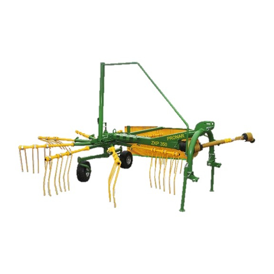
ROTARY WINDROWER RAKES
PRONAR ZKP350
Translation of the original instructions
+48 085 681 63 29
+48 085 681 63 81
+48 085 681 63 83
PUBLICATION NO 179N-00000000-UM
+48 085 681 64 29
+48 085 681 63 82
+48 085 682 71 10
www.pronar.pl
GB
Advertisement
Table of Contents

Subscribe to Our Youtube Channel
Related Manuals for PRONAR ZKP350


Summary of Contents for PRONAR ZKP350
- Page 1 PRONAR Sp. z o.o. 17-210 NAREW, UL. MICKIEWICZA 101A, PODLASKIE PROVINCE tel.: +48 085 681 63 29 +48 085 681 64 29 +48 085 681 63 81 +48 085 681 63 82 fax: +48 085 681 63 83 +48 085 682 71 10 www.pronar.pl...
- Page 3 ROTARY WINDROWER RAKES PRONAR ZKP 350 MACHINE IDENTIFICATION SYMBOL /TYPE: ZKP 350 SERIAL NUMBER:...
- Page 4 If the information contained in the operating instructions needs clarification then the user should refer for assistance to the sale point where the machine was purchased or to the manufacturer. Manufacturer's address: PRONAR Sp. z o.o. ul. Mickiewicza 101A 17-210 Narew Contact telephones...
- Page 5 Information, descriptions of danger and precautions and also recommendations and orders associated with user safety instructions are marked: and also preceded by the word "DANGER”. Failure to observe the instructions may endanger the machine operator's or other person's health or life. Particularly important information and instructions, the observance of which is essential, are distinguished in the text by the sign: and also preceded either word "ATTENTION".
-
Page 7: Table Of Contents
TABLE OF CONTENTS BASIC INFORMATION IDENTIFICATION INTENDED USE FITTINGS WARRANTY CONDITIONS TRANSPORT ENVIRONMENTAL HAZARDS WITHDRAWAL FROM USE SAFETY IN USE BASIC SAFETY PRINCIPLES PRINCIPLES WHEN TRAVELLING ON PUBLIC ROADS DESCRIPTION OF MINIMAL RISK INFORMATION AND WARNING STICKERS CONSTRUCTION AND PRINCIPLE OF OPERATION TECHNICAL SPECIFICATION ROTARY WINDROWER RAKES DESIGN HITCHING SYSTEM... - Page 8 TECHNICAL MAINTENANCE PRINCIPLES OF SAFE TRACTOR OPERATION REDUCTION GEAR OPERATION STORAGE LUBRICATION INSPECTION AND CHANGING RAKING FINGERS TIGHTENING TORQUE FOR NUT AND BOLT CONNECTIONS...
-
Page 9: Basic Information
SECTION BASIC INFORMATION IDENTIFICATION INTENDED USE FITTINGS WARRANTY CONDITIONS TRANSPORT ENVIRONMENTAL HAZARDS WITHDRAWAL FROM USE... -
Page 10: Identification
1.1 IDENTIFICATION FIGURE 1.1A Location of the data plate (1) data plate The ZKP 350 rotary windrower is marked with a data plate (1), placed on left side of machine's lifting arm. When buying the rotary windrower check that the serial numbers on the machine agree with the number written in the WARRANTY BOOK, in the sales documents and in the OPERATING INSTRUCTIONS. -
Page 11: Intended Use
F - Quality control stamp, G - machine name, name extension. 1.2 INTENDED USE Rotary windrower rakes are designed for agricultural work: raking cut swaths (straw, grass, hays) and gathering it into windrows on stone free grassland with a level surface. Do NOT use the machine for any other purpose. -
Page 12: Fittings
T200860EN112U24 Comer. 1.4 WARRANTY CONDITIONS PRONAR Sp. z o.o., Narew guarantees the reliable operation of the machine when it is used according to its intended purpose as described in the OPERATOR'S MANUAL. The repair period is specified in the WARRANTY BOOK. - Page 13 The guarantee does not cover those parts and sub-assemblies of the machine which are subject to wear in normal usage conditions, regardless of the warranty period. Consumables include the following parts/sub-assemblies: • tyres, • spring tine fingers, • bearings. The warranty service only applies to such cases as: mechanical damage which is not the user's fault, factory defects of parts, etc.
-
Page 14: Transport
1.5 TRANSPORT The windrower is prepared for sale in a completely assembled condition and does not require packing. Packing consists solely of the machine's technical documentation and operating instructions. ATTENTION! When transporting independently, the user must familiarise himself with the content of these instructions and observe their recommendations. - Page 15 FIGURE 1.2A Points of windrower suspension (1) transport lug, (2) central connection pin DANGER During loading, windrower should be placed in transport position. Extending arm and the forming shield should be dismantled. The windrower should be attached firmly to the platform of the vehicle using straps or chains fitted with a tightening mechanism.
-
Page 16: Environmental Hazards
vehicle. During reloading work, particular care should be taken not to damage parts of the windrower's fittings or the paint coat. 1.6 ENVIRONMENTAL HAZARDS A hydraulic oil leak from the reducer constitutes a direct threat to the natural environment owing to its limited biodegradability. While carrying out maintenance and repair work which involves the risk of an oil leak, this work should take place on an oil resistant floor or surface. -
Page 17: Safety In Use
SECTION SAFETY IN USE BASIC SAFETY PRINCIPLES PRINCIPLES WHEN TRAVELLING ON PUBLIC ROADS DESCRIPTION OF MINIMAL RISK INFORMATION AND WARNING STICKERS... -
Page 18: Basic Safety Principles
Anyone who uses the machine other than the way intended takes full responsibility on himself for any consequences of this use. • Any modification to the windrower frees PRONAR Narew from any responsibility for damage or detriment to health which may arise as a result. •... - Page 19 • Windrower disconnected from tractor must be supported with the aid of supports and secured against rolling away by using wheel wedges or other elements without sharp edges. • Do NOT ride on the windrower or transport any materials on it. •...
- Page 20 • The chains preventing the shaft cover from turning while the shaft is working, shall be secured to a fixed element of windrower structure. • Do NOT use the securing chains to support the shaft while machine is parked or when transporting the windrower.
- Page 21 • In order to reduce the danger of fire the machine must be kept in a clean condition. • In the event of work requiring the windrower to be raised, use properly certified hydraulic or mechanical lifts for this purpose. After lifting the windrower, stable and durable supports must also be used.
-
Page 22: Principles When Travelling On Public Roads
2.3 DESCRIPTION OF MINIMAL RISK Pronar Sp. z o. o. in Narew has made every effort to eliminate the risk of accidents. There is, however, a certain minimal risk which could lead to an accident, and this is connected mainly with the actions described below: •... -
Page 23: Information And Warning Stickers
• not keeping a safe distance from the danger zone or being within the zones while the windrower is operating, • operation of the windrower by persons under the influence of alcohol, • cleaning, maintenance and technical checks of the windrower. •... - Page 24 TABLE 2.1 INFORMATION AND WARNING STICKERS ITEM SAFETY SYMBOL DESCRIPTION Before starting work, familiarise yourself with the contents of the OPERATING INSTRUCTIONS. Before beginning servicing or repairs, switch off engine and remove key from ignition Danger associated with the rotating articulated telescopic shaft.
- Page 25 ITEM SAFETY SYMBOL DESCRIPTION Danger of crushing or severing of limbs. Be careful while folding and unfolding side guards. Thrown out objects, danger to the whole body. Keep a safe distance from machine during work of windrower. Danger of being struck by rotating elements of the machine.
- Page 26 FIGURE 2.1A Locations of information and warning stickers. Labelling in line with table 2.1 „Information and warning stickers”. 2.10...
-
Page 27: Construction And Principle Of Operation
SECTION CONSTRUCTION AND PRINCIPLE OF OPERATION TECHNICAL SPECIFICATION ROTARY WINDROWER RAKES DESIGN HITCHING SYSTEM OPERATING PRINCIPLE... -
Page 28: Technical Specification
3.1 TECHNICAL SPECIFICATION TABLE 3.1 ROTARY WINDROWER RAKES TECHNICAL DATA CONTENTS UNIT ZKP 350 Dimensions Total length in working setting 3 250 Total length in transport setting 2,430 Width in working setting minimum 3,405 maximum 3,905 Width in transport setting 1 110 Height in working setting 1,120... - Page 29 FIGURE 3.1A Rotary windrower rakes design (1) frame, (2) reducer, (3) raking arm, (4) extender, (5) springtine finger, (6) securing angle, (7) linchpin, (8) wheel beam, (9) undercarriage leg, (10) wheel, (11) extension arm, (12) shield, (13), (14) shield wing struts, (15) support, (16) regulation screw, (17) screw lock...
-
Page 30: Hitching System
The transmission gearing (2) has 9 radiating shafts, to which are secured raking arms (3). Each of the arms is equipped with 3 springtine fingers for raking the swath. They are mounted on the arm extension with the aid of securing angles (6), which prevent fingers from sliding or rotating. - Page 31 FIGURE 3.2A Hitching system (1), (2) lower securing pins (three-point linkage – II category), (3), (4) lower securing pins (three-point linkage – I category), (5) upper securing pin, (6), (7) locking linchpins, (A) working pin position socket, (B) travelling pin position socket...
-
Page 32: Operating Principle
3.4 OPERATING PRINCIPLE The rotary windrower rakes is equipped with the reduction gearing driven by the tractor PTO. The torque is transferred through transfer shafts. The reducer's design ensures the rotation movement of the raking assembly in an anticlockwise direction. The gear's cam mechanism enables the rotation of individual arms, due to which the springtine fingers are lowered or raised according to current setting. -
Page 33: Correct Use
SECTION CORRECT USE PREPARING FOR WORK BEFORE FIRST USE TECHNICAL INSPECTION OF WINDROWER ATTACHING TO TRACTOR PREPARATION OF WINDROWER FOR WORK CONNECTING DRIVESHAFT RAKING DISCONNECTING THE WINDROWER PREPARATION OF WINDROWER FOR TRANSPORT... -
Page 34: Preparing For Work Before First Use
4.1 PREPARING FOR WORK BEFORE FIRST USE The manufacturer guarantees that the windrower is fully operational and has been checked according to quality control procedures and is ready for normal use. This does not release the user from an obligation to check the machine's condition after delivery and before first use. - Page 35 Engage rake drive for several minutes, and check the following: • there is no knocking or noise in the drive system arising from scraping or grinding of metal elements, • proper rotation of raking system, • proper action of cam mechanism (raking fingers should be lowered and raised according to current arm position).
-
Page 36: Technical Inspection Of Windrower
If any faults are detected they must be identified and rectified. If a fault cannot be rectified or the repair could void the guarantee, please contact retailer for additional clarifications. 4.2 TECHNICAL INSPECTION OF WINDROWER When preparing the windrower for normal use, check individual elements according to guidelines presented in table (4.1). -
Page 37: Attaching To Tractor
4.3 ATTACHING TO TRACTOR FIGURE 4.1A Attaching windrower to tractor (1), (2) lower three-point linkage securing pins, (3) upper securing pins, (4) support, (5) locking linchpin, (A), (B) lower three-point linkage hitching points, (C) upper three-point linkage connection The windrower may only be connected to tractors with power output greater than 25 hp, equipped with category I or II rear three-point linkage. -
Page 38: Preparation Of Windrower For Work
• Reversing the tractor bring the lower three-point linkage connection points (A) and (B) close to pins (1) and (2) of windrower. • Set connection arms (A) and (B) of tractor at appropriate height. • Switch off tractor's engine and prevent it from rolling. •... -
Page 39: Mounting Of Raking Arms
4.4.1 MOUNTING OF RAKING ARMS FIGURE 4.2A mounting of raking arms (1) locking linchpin, (2) raking arm, (3) securing of arm • Stop tractor and remove the key from the ignition, ensure that unauthorised persons do not have access to the tractor. •... -
Page 40: Setting Guards
ATTENTION! Raking arms in transport position secured with the aid of 2 linchpins (1 linchpin for each side). These linchpins are used to secure raking arms in working position. DANGER Do NOT operate the machine when the complete set of 9 raking arms is not installed. Raking arms shall be mounted with tractor engine switched off. - Page 41 The forming guard is the barrier for the raked swath. Thanks to the swath is formed into an even windrow of the required width. When setting the guard observe the principle that the greater the swath then the wider the working width, and the other way round, the lower the quantity of swath then the barrier distance should be less.
-
Page 42: Setting Working Height
IMPORTANT! Read the instructions on regulation of the three-point linkage which are part of the tractor's operating instructions. FIGURE 4.4A Setting working height (1) crank, (2) counter nut, (3) reduction gearing Regulation of working position is performed after lowering the machine to the ground. Working position of windrower is regulated by performing the following actions: •... -
Page 43: Connecting Driveshaft
• Regulate height of windrower using the crank in such a way that the rake assembly is in a horizontal plane – parallel to the ground surface and the springtine fingers lightly touch the ground, the top link pin should be in the middle of the sliding socket, •... -
Page 44: Raking
DANGER Before connecting the shaft, turn off the tractor's engine and remove the key from the ignition. Ensure that unauthorised persons do not have access to the tractor. The use of articulated telescopic shaft and its technical condition must be in accord with the operating instructions of articulated telescopic shaft. -
Page 45: Disconnecting The Windrower
into windrow. Allowable revolution speed of articulated telescopic shaft is 540 revs/min however recommended speed is about 450 revs/min. With a very dry swath it is recommended that PTO shaft speed should be reduced even further. IMPORTANT! Do NOT start windrower with PTO revs speed higher than 540 revs/min. The revolution speed of the shaft and the speed of travel depend on several factors, including size of swath, degree of moisture, length of swath, type of ground, therefore the selection of appropriate working parameters rests on the person operating the windrower. -
Page 46: Preparation Of Windrower For Transport
• disconnect lower windrower pins and drive tractor away. 4.8 PREPARATION OF WINDROWER FOR TRANSPORT After finishing fieldwork the windrower must be set in transport position. Before beginning preparation works switch of tractor engine and remove the key from the ignition. Brake tractor with parking brake and secure tractor cab, ensure that unauthorised persons do not have access to the tractor. -
Page 47: Technical Maintenance
SECTION TECHNICAL MAINTENANCE PRINCIPLES OF SAFE TRACTOR OPERATION REDUCTION GEAR OPERATION STORAGE LUBRICATION INSPECTION AND CHANGING RAKING FINGERS TIGHTENING TORQUE FOR NUT AND BOLT CONNECTIONS... - Page 48 5.1 SAFE MAINTENANCE PRINCIPLES • Repair, maintenance and cleaning work should be carried out with the tractor's engine switched off and the ignition key removed. Ensure that unauthorised persons, especially children, do not have access to the tractor. • The machine must not be used when not in working order. •...
- Page 49 FIGURE 5.1A Changing reduction gear oil (1) inlet plug In order to change oil in reducer: • set windrower on a hard surface and level the machine • unscrew inlet plug (1), • unscrew drain plug on lower part of reducer, •...
- Page 50 The first oil change should be made after 50 hours of windrower work and the next change should be after 500 hours or once a year. During normal operation, lubrication of the entry shaft and the windrower's height regulation screw is also required – consult section "Lubrication”. If a leak is noticed, carefully inspect seals and check oil level.
- Page 51 Tyres should undergo conservation maintenance at least twice a year using the appropriate preparations designed for this purpose. Complete wheels and tyres should be previously carefully washed and dried. During longer storage of unused windrower it is recommended that every 2 to 3 weeks the trailer may be moved a bit so that the place of contact of tyres with ground is changed.
- Page 52 FIGURE 5.2A Windrower greasing points...
-
Page 53: Inspection And Changing Raking Fingers
TABLE 5.1 GREASING POINTS NUMBER TYPE OF GREASING NAME GREASING GREASE FREQUENCY POINTS Undercarriage strut arms PERMANENT 40 hours Shaft bearing PERMANENT 20 hours Multi-splined driveshaft PERMANENT 20 hours Reduction gear bearing PERMANENT 20 hours Gear: 500 hours Regulation screw PERMANENT 60 hours 8 hours... - Page 54 Raking fingers and their mounting should be checked while working with windrower. Damaged elements should be replaced. It is not possible to repair raking fingers. Each day check condition of raking finger connections to arms and locking linchpins on raking arms frame in case they have fallen out FIGURE 5.3A Changing raking fingers (1) raking finger, (2) securing angle, (3) screw, (4) self-locking nut...
-
Page 55: Tightening Torque For Nut And Bolt Connections
5.6 TIGHTENING TORQUE FOR NUT AND BOLT CONNECTIONS Unless other tightening parameters are given, during maintenance repair work apply appropriate torque to tightening nut and bolt connections. Recommended tightening torque of most frequently applied nut and bolt connections are given in table (5.2). Given values apply to non greased steel bolts. - Page 56 10.9 THREAD (d) [mm] [Nm] 1050 1150 1650 1050 1450 2100 ) – tightening torque, (d) thread diameter 5.10...
- Page 57 NOTES ………………………………………………………………………………………………………………………………….. ………………………………………………………………………………………………………………………………….. ………………………………………………………………………………………………………………………………….. ………………………………………………………………………………………………………………………………….. ………………………………………………………………………………………………………………………………….. ………………………………………………………………………………………………………………………………….. ………………………………………………………………………………………………………………………………….. ………………………………………………………………………………………………………………………………….. ………………………………………………………………………………………………………………………………….. ………………………………………………………………………………………………………………………………….. ………………………………………………………………………………………………………………………………….. ………………………………………………………………………………………………………………………………….. ………………………………………………………………………………………………………………………………….. ………………………………………………………………………………………………………………………………….. ………………………………………………………………………………………………………………………………….. ………………………………………………………………………………………………………………………………….. ………………………………………………………………………………………………………………………………….. ………………………………………………………………………………………………………………………………….. ………………………………………………………………………………………………………………………………….. ………………………………………………………………………………………………………………………………….. ………………………………………………………………………………………………………………………………….. ………………………………………………………………………………………………………………………………….. ………………………………………………………………………………………………………………………………….. ………………………………………………………………………………………………………………………………….. ………………………………………………………………………………………………………………………………….. …………………………………………………………………………………………………………………………………..
- Page 58 ………………………………………………………………………………………………………………………………….. ………………………………………………………………………………………………………………………………….. ………………………………………………………………………………………………………………………………….. ………………………………………………………………………………………………………………………………….. ………………………………………………………………………………………………………………………………….. ………………………………………………………………………………………………………………………………….. ………………………………………………………………………………………………………………………………….. ………………………………………………………………………………………………………………………………….. ………………………………………………………………………………………………………………………………….. ………………………………………………………………………………………………………………………………….. ………………………………………………………………………………………………………………………………….. ………………………………………………………………………………………………………………………………….. ………………………………………………………………………………………………………………………………….. ………………………………………………………………………………………………………………………………….. ………………………………………………………………………………………………………………………………….. ………………………………………………………………………………………………………………………………….. ………………………………………………………………………………………………………………………………….. ………………………………………………………………………………………………………………………………….. ………………………………………………………………………………………………………………………………….. ………………………………………………………………………………………………………………………………….. ………………………………………………………………………………………………………………………………….. ………………………………………………………………………………………………………………………………….. ………………………………………………………………………………………………………………………………….. ………………………………………………………………………………………………………………………………….. ………………………………………………………………………………………………………………………………….. ………………………………………………………………………………………………………………………………….. ………………………………………………………………………………………………………………………………….. ………………………………………………………………………………………………………………………………….. ………………………………………………………………………………………………………………………………….. …………………………………………………………………………………………………………………………………..
Need help?
Do you have a question about the ZKP350 and is the answer not in the manual?
Questions and answers