Table of Contents
Advertisement
Quick Links
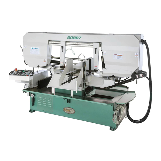
MODEL G0887
20" X 26" 5 HP INDUSTRIAL
METAL-CUTTING BANDSAW
OWNER'S MANUAL
(For models manufactured since 01/19)
COPYRIGHT © JUNE, 2021 BY GRIZZLY INDUSTRIAL, INC.
WARNING: NO PORTION OF THIS MANUAL MAY BE REPRODUCED IN ANY SHAPE
OR FORM WITHOUT THE WRITTEN APPROVAL OF GRIZZLY INDUSTRIAL, INC.
#CS20972 PRINTED IN TAIWAN
V1.06.21
Advertisement
Table of Contents

Subscribe to Our Youtube Channel
Related Manuals for Grizzly G0887


Summary of Contents for Grizzly G0887
- Page 1 (For models manufactured since 01/19) COPYRIGHT © JUNE, 2021 BY GRIZZLY INDUSTRIAL, INC. WARNING: NO PORTION OF THIS MANUAL MAY BE REPRODUCED IN ANY SHAPE OR FORM WITHOUT THE WRITTEN APPROVAL OF GRIZZLY INDUSTRIAL, INC. #CS20972 PRINTED IN TAIWAN V1.06.21...
- Page 2 This manual provides critical safety instructions on the proper setup, operation, maintenance, and service of this machine/tool. Save this document, refer to it often, and use it to instruct other operators. Failure to read, understand and follow the instructions in this manual may result in fire or serious personal injury—including amputation, electrocution, or death.
-
Page 3: Table Of Contents
Table of Contents INTRODUCTION ..........2 SECTION 5: ACCESSORIES ......47 Contact Info............ 2 SECTION 6: MAINTENANCE ......49 Manual Accuracy ........... 2 Schedule ............49 Identification ........... 3 Cleaning & Protecting ........49 Controls & Components ......... 4 Lubrication ........... 50 Machine Data Sheet ........ -
Page 4: Introduction
ID label (see below). This information is required for us to provide proper tech support, and it helps us determine if updated documentation is available for your machine. Manufacture Date Serial Number Model G0887 (Mfd. Since 01/19) -
Page 5: Identification
Blade Speed Display Rear View Blade Speed Dial Coolant Valve (1 of 3) Vise Lock Handle Movable Vise Jaw Fixed Vise Jaw To reduce your risk of serious injury, read this entire manual BEFORE using machine. Model G0887 (Mfd. Since 01/19) -
Page 6: Controls & Components
E. Work Stop: Provides outfeed scale for repet- Figure 4. Electrical cabinet power switch. itive cutting operations. Master Power ON/OFF Switch: Turns Support Vise: Adjusts to provide outfeed incoming power ON and OFF. workpiece support. Model G0887 (Mfd. Since 01/19) - Page 7 : Enters angle AD. Master Power ON/OFF Key Switch: Turns incoming power ON and OFF when key is entry mode to edit headstock angle. inserted. Coolant Pump Button : Turns coolant pump ON and OFF. Model G0887 (Mfd. Since 01/19)
-
Page 8: Machine Data Sheet
Machine Data Sheet MACHINE DATA SHEET Customer Service #: (570) 546-9663 · To Order Call: (800) 523-4777 · Fax #: (800) 438-5901 MODEL G0887 20" X 26" 5 HP INDUSTRIAL METAL‐ CUTTING BANDSAW Product Dimensions: Weight................................3747 lbs. Width (side-to-side) x Depth (front-to-back) x Height................. 119 x 63 x 70 in. - Page 9 The information contained herein is deemed accurate as of 11/8/2021 and represents our most recent product specifications. Model G0887 PAGE 2 OF 3 Due to our ongoing improvement efforts, this information may not accurately describe items previously purchased. Model G0887 (Mfd. Since 01/19)
- Page 10 The information contained herein is deemed accurate as of 11/8/2021 and represents our most recent product specifications. Model G0887 PAGE 3 OF 3 Due to our ongoing improvement efforts, this information may not accurately describe items previously purchased. Model G0887 (Mfd. Since 01/19)
-
Page 11: Section 1: Safety
Never operate under the influence of drugs or injury or blindness from flying particles. Everyday alcohol, when tired, or when distracted. eyeglasses are NOT approved safety glasses. Model G0887 (Mfd. Since 01/19) - Page 12 Make sure they are properly installed, you experience difficulties performing the intend- undamaged, and working correctly BEFORE ed operation, stop using the machine! Contact our operating machine. Technical Support at (570) 546-9663. -10- Model G0887 (Mfd. Since 01/19)
-
Page 13: Additional Safety For Horizontal Metal Bandsaws
Spilled cutting fluid invites slip- HOT SURFACES. Contact with hot surfaces from ping hazards. machine components, ejections of hot chips, swarf, and the workpiece itself can cause burns. -11- Model G0887 (Mfd. Since 01/19) -
Page 14: Additional Safety For Hydraulic Systems
If normal safety pre- respect. Failure to do so could result in cautions are overlooked or ignored, seri- serious personal injury, damage to equip- ous personal injury may occur. ment, or poor work results. -12- Model G0887 (Mfd. Since 01/19) -
Page 15: Section 2: Power Supply
To reduce the risk of these hazards, avoid over- loading the machine during operation and make sure it is connected to a power supply circuit that meets the specified circuit requirements. -13- Model G0887 (Mfd. Since 01/19) - Page 16 -14- Model G0887 (Mfd. Since 01/19)
-
Page 17: Section 3: Setup
Grizzly or the shipping agent. You MUST have the original pack- aging to file a freight claim. It is also extremely helpful if you need to return your machine later. -
Page 18: Inventory
If you cannot find an item on this list, care- fully check around/inside the machine and packaging materials. Often, these items get lost in packaging materials while unpack- ing or they are pre-installed at the factory. Figure 7. Box inventory. -16- Model G0887 (Mfd. Since 01/19) -
Page 19: Hardware Recognition Chart
Hardware Recognition Chart USE THIS CHART TO MATCH UP HARDWARE DURING THE INVENTORY AND ASSEMBLY PROCESS. Flat Head Screw -17- Model G0887 (Mfd. Since 01/19) -
Page 20: Cleanup
Figure 8. T23692 Orange Power Degreaser. Repeat Steps 2–3 as necessary until clean, then coat all unpainted surfaces with a quality metal protectant to prevent rust. -18- Model G0887 (Mfd. Since 01/19) -
Page 21: Site Considerations
Shadows, glare, or strobe effects that may distract access restricted location. or impede the operator must be eliminated. Keep Area Unobstructed = Electrical Connection 134" Min. 30" for Maintenance Keep Area Unobstructed 167½" Figure 9. Minimum working clearances. -19- Model G0887 (Mfd. Since 01/19) -
Page 22: Assembly
Figure 11. Lifting machine with forklift example. shipping crate and removing machine from crate. Seek assistance from a professional rigger if you are unsure about your abili- ties or maximum load ratings of your lifting equipment. -20- Model G0887 (Mfd. Since 01/19) - Page 23 Figure 13. Support Vise Guide Scale Figure 15. Support vise guide installed on base shaft. Hole Work Stop Bar Figure 13. Work stop installed. -21- Model G0887 (Mfd. Since 01/19)
-
Page 24: Power Connection
Follow Test Run to ensure that machine of electrical components on your machine. If you functions properly. must use an extension cord, refer to Extension Cords on Page 14 for more information. -22- Model G0887 (Mfd. Since 01/19) -
Page 25: Test Run
Test Run. Fill coolant reservoir with coolant (refer to Coolant System Maintenance on Page 56), if you have not already done so. DO NOT run pump without coolant or you will damage it. -23- Model G0887 (Mfd. Since 01/19) - Page 26 (U), vise close button (R), then blade brush spins. The machine should run smooth- start button (S). ly and without unusual problems or noises. Figure 18. G0887 control panel. -24- Model G0887 (Mfd. Since 01/19)
-
Page 27: Recommended Adjustments
Factory adjustments that should be verified: Downfeed Stop Bolt (Page 72). Blade Tracking (Page 68). Blade Guide Bearings (Page 66). Squaring Blade to Table (Page 70). Figure 19. Blade cover secure screws (2 of 4). Hydraulic Pressure (Page 53). -25- Model G0887 (Mfd. Since 01/19) -
Page 28: Section 4: Operations
Regardless of the content in this sec- 16. Once machine has stopped, turns machine tion, Grizzly Industrial will not be held liable OFF then removes workpiece. for accidents caused by lack of training. -
Page 29: Disabling Switch
• Use coolant when possible to increase blade life. Loosen blade tension at the end of each day to prolong blade life. -27- Model G0887 (Mfd. Since 01/19) -
Page 30: Workpiece Inspection
Blade Pitch or TPI: Number of teeth per inch ily. Cutting magnesium with a dull blade can measured from gullet to gullet. create enough friction to ignite the small magnesium chips. Avoid cutting magnesium if possible. -28- Model G0887 (Mfd. Since 01/19) - Page 31 Material Width/Diameter Teeth Per Inch (TPI) for Bandsaw Blades Material Shapes TOOTH SELECTION 1.5/.8 1.4/2.5 1.4/2.5 1.5/.8 inch 2½ 3½ 14 15 Figure 23. General guidelines for blade selection and speed chart. -29- Model G0887 (Mfd. Since 01/19)
-
Page 32: Blade Breakage
Choose correct speed for blade and material type. Reduce feed rate by half for first 50–100 in of material cut. To avoid twisting blade when cutting, adjust feed rate when total width of blade is in cut. -30- Model G0887 (Mfd. Since 01/19) -
Page 33: Setting Blade Feed Rate
Changing Blade Rate Speed The speed at which the saw blade will cut through Model G0887 blade speeds: 106–315 FPM. a workpiece is determined by blade type, feed rate, and feed pressure. The feed rate is con- NOTICE trolled by the blade feed-rate dial on the control panel. -
Page 34: Blade Speed Chart
Tool Steel (62) Steel (26) Cast Iron (98) Oil- Copper 229~482 203~213 85~203 Plastics & Hardened Stainless Alloy (70) (147) (62) (65) (26) (62) Lumber (67) Tool Steel Steel Figure 26. Blade speed chart. -32- Model G0887 (Mfd. Since 01/19) -
Page 35: Chip Inspection Chart
Hard, Coiled & Check Blade Silver Increase Decrease Thin Pitch Straight & Thin Silver Good Increase Powdery Silver Decrease Increase Coiled, Tight & Check Blade Silver Good Decrease Thin Pitch Figure 27. Chip inspection chart. -33- Model G0887 (Mfd. Since 01/19) -
Page 36: Changing Blade
(see Figure 28). Release blade tension by turning blade tension handwheel counterclockwise (see Figure 30). Blade Tension Handwheel Figure 28. Blade cover secure screws (2 of 4). Figure 30. Location of blade tension handwheel. -34- Model G0887 (Mfd. Since 01/19) - Page 37 Guides on Page 37 for details). (see Figure 32). Some blades will have a directional arrow as a guide. Figure 32. Example of blade cutting direction. -35- Model G0887 (Mfd. Since 01/19)
-
Page 38: Tensioning Blade
Left Blade Guide Arm Figure 34. Wheel cover secure screws (2 of 4). Figure 36. Left blade guide adjustable handle. Perform quick blade tracking check by sliding fingernail between end of blade and wheel shoulder. -36- Model G0887 (Mfd. Since 01/19) -
Page 39: Adjusting Blade Guides
The right blade guide has a wire brush that makes contact with the blade to help clear away chips and extend blade life (see Figure 39). Blade Brush (Hidden By Guard) Figure 39. Blade brush location. -37- Model G0887 (Mfd. Since 01/19) -
Page 40: Adjusting Blade Guard Extension
DISCONNECT MACHINE FROM POWER! Extension Open wheel cover by removing (4) button Figure 41. Blade guard extension components. head cap screws (see Figure 40). Figure 40. Wheel cover secure screw locations (2 of 4). -38- Model G0887 (Mfd. Since 01/19) -
Page 41: Manual & Automatic Controls
Open vise ( ), place workpiece for cut, then close vise ( Proceed to Performing an Automatic Cut. The Model G0887 has two operation modes: automatic and manual. Manual mode includes Performing an Automatic Cut the controls necessary to prepare a workpiece... -
Page 42: Identifying Failures
H. Vise: Open and close vise to secure will not raise further when height value is workpiece (see Using Vise on Page 42). reached. Emergency Stop Button: Emergency Stop button is depressed. Twist to reset. -40- Model G0887 (Mfd. Since 01/19) -
Page 43: Setting Headstock Angle
— As headstock approaches target angle, headstock will jog and stop so as not to pass target. -41- Model G0887 (Mfd. Since 01/19) -
Page 44: Using Vise
Turn on hydraulic pump ( ). Raise headstock ( ) to highest position. The Model G0887 vise consists of a movable vise jaw that is manually positioned near the Note: If headstock does not clear vise and workpiece, hydraulic vise clamping controls for... - Page 45 Opening and Closing Vise The hydraulics that open and close the movable vise can be adjusted using the control panel (see Figure 50). Vise Close Button Vise Open Button Figure 50. Vise controls. -43- Model G0887 (Mfd. Since 01/19)
-
Page 46: Adjusting Support Vise Guide
Adjusting Adjusting Work Stop Support Vise Guide The Model G0887 is equipped with a work stop for repetitive cutting operations up to 24" long. The support vise guide provides workpiece sup- The work stop will need to be adjusted any time it port on the outfeed side of the cut, guiding cut-off is removed or repositioned. -
Page 47: Using Coolant System
(see Figure 56). sonal protection equipment when handling coolant and follow federal, state, and Workpiece fluid manufacturer require- Work Stop ments to properly dispose of coolant. Figure 56. Work stop set for cutting operation. -45- Model G0887 (Mfd. Since 01/19) - Page 48 Press coolant pump button ( ). Coolant will now spray when the trigger is pressed (see Figure 59). Figure 57. Coolant valve (1 of 3) open. Figure 59. Example of spray gun in use. -46- Model G0887 (Mfd. Since 01/19)
-
Page 49: Section 5: Accessories
Can be used on all metals except To reduce this risk, only install accessories titanium. recommended for this machine by Grizzly. NOTICE Refer to our website or latest catalog for additional recommended accessories. - Page 50 Milwaukee® Performance Work Gloves are designed to provide ultimate durability and all day comfort. Figure 67. Model T30024 Powered Respirator Kit. Figure 65. Milwaukee® Performance Work Gloves. www.grizzly.com 1-800-523-4777 order online at or call -48- Model G0887 (Mfd. Since 01/19)
-
Page 51: Section 6: Maintenance
Lubricate blade guide arm gib (Page 52). • Lubricate front wheel axle (Page 52). • Lubricate blade tension leadscrew (Page 53). Monthly Check • Inspect drive belt (Page 58). Figure 68. Boeshield® T-9 spray. -49- Model G0887 (Mfd. Since 01/19) -
Page 52: Lubrication
ISO 68 Oil (SB1365 or Equivalent) ..As Needed 12 oz. AMGA#2 (ISO 68 Equivalent) Clean Shop Rags ........As Needed Grease Gun ..............1 Stiff Brush ..............1 Clean Brush ..............1 Hex Wrench 4, 5mm .........1 Ea. Figure 71. Model SB1365 Way Oil. -50- Model G0887 (Mfd. Since 01/19) - Page 53 Keep the vise and table (see Figure 73) surface rust-free with regular applications of a quality way oil. Hydraulic Cylinder Bearing Grease Fitting Figure 75. Hydraulic cylinder bearing grease fitting location. Figure 73. Table and vise. -51- Model G0887 (Mfd. Since 01/19)
- Page 54 Apply grease to vise shaft using grease fitting shown in Figure 77. ting shown in Figure 79. Front Wheel Axle Vise Shaft Grease Fitting Grease Fitting Figure 77. Vise shaft grease fitting location. Figure 79. Front wheel axle grease fitting location. -52- Model G0887 (Mfd. Since 01/19)
-
Page 55: Hydraulic System
Hex Wrench 4mm ..........1 Open-End Wrench 17, 27mm ......1 Ea. To check hydraulic pressure: Raise/lower headstock repeatedly for approx- imately 10 minutes to warm up hydraulic fluid. DISCONNECT MACHINE FROM POWER! Figure 81. Blade tension leadscrew location. -53- Model G0887 (Mfd. Since 01/19) - Page 56 498 PSI or less (see Hydraulic System Diagram on Page 77). Note: Connect machine to power and Figure 84. Hydraulic tank fluid gauge and fill cap run hydraulic system to check pressure location. adjustment. -54- Model G0887 (Mfd. Since 01/19)
- Page 57 Raise/lower headstock repeatedly for approx- Clean fill cap and fill screen (see Figure 85) imately 10 minutes to warm up hydraulic fluid. with mineral spirits and allow to air dry. DISCONNECT MACHINE FROM POWER! -55- Model G0887 (Mfd. Since 01/19)
-
Page 58: Coolant System Maintenance
When working with the coolant, minimize expo- access panel. sure to your skin, eyes, and lungs by wearing the proper PPE (Personal Protective Equipment), such as long-sleeve waterproof gloves, protective clothing, splash-resistant safety goggles, and a NIOSH-approved respirator. -56- Model G0887 (Mfd. Since 01/19) - Page 59 To change coolant: DISCONNECT MACHINE FROM POWER! Remove chip collection drawer from machine base (see Figure 89) and clean drawer. Figure 89. Removing chip collection drawer. Mix coolant according to cutting fluid manu- facturer's specifications. -57- Model G0887 (Mfd. Since 01/19)
-
Page 60: Inspecting Drive Belt
Clean and wrap drain plug threads with Teflon tape, then install drain plug. Mix 10 gallons of coolant according to cutting fluid manufacturer's specifications, then refill tank with coolant. Replace chip collection drawer. -58- Model G0887 (Mfd. Since 01/19) -
Page 61: Storing Machine
Cover machine with tarp or plastic sheet that will keep out dust and resist moisture. If machine will be near direct sunlight, use cover that will block sun's rays. -59- Model G0887 (Mfd. Since 01/19) -
Page 62: Section 7: Service
3. Wiring broken, disconnected, or corroded. 3. Replace/fix broken, disconnected, or corroded wires. 4. Electrical cabinet or control panel circuit 4. Inspect/replace if at fault. board at fault. 5. Coolant pump motor at fault. 5. Test/repair/replace. -60- Model G0887 (Mfd. Since 01/19) - Page 63 6. Pulley loose/misaligned. 6. Re-align/replace shaft, pulley, set screw, and key. 7. Motor bearings at fault. 7. Turn shaft; loose shaft requires bearing replacement. 8. Gearbox at fault. 8. Rebuild gearbox and replace bad gear(s)/bearing(s). -61- Model G0887 (Mfd. Since 01/19)
- Page 64 5. Adjust blade tracking (Page 68), tension (Page 36). 6. Adjust blade guide roller bearings (Page 66). 6. Blade guide roller bearings require adjustment. 7. Blade weld may be failing. 7. Cut and reweld blade, or replace blade (Page 34). -62- Model G0887 (Mfd. Since 01/19)
- Page 65 4. Control panel or electrical cabinet wiring at 4. Check that hydraulic pump motor is running and fault. that solenoids are activating (indicated by red LED in solenoid plug). Repair/replace if at fault. 5. Hydraulic pump at fault. 5. Test/repair/replace. -63- Model G0887 (Mfd. Since 01/19)
- Page 66 6. Test/repair/replace. Cooling system is 1. Coolant needs to be changed/reservoir is 1. Clean and change coolant (Page 57). pulling sludge from dirty. 2. Check/fill coolant level (Page 57). reservoir. 2. Coolant level is low. -64- Model G0887 (Mfd. Since 01/19)
-
Page 67: Adjusting Blade Brush
Blade Brush power before adjustments, maintenance, or service. The Model G0887 has a blade brush to help keep metal chips off the blade wheels. It will wear over time and require re-adjustment when it no longer Wing Nut makes proper contact with the blade. -
Page 68: Adjusting Blade Guides & Bearings
On left blade guide, verify back of blade lightly contacts upper carbide blade guide (see Figure 98). Upper Blade Guide Blade Figure 96. Wheel cover secure screw locations Cap Screws (2 of 4). Figure 98. Upper carbide blade guide adjustment components. -66- Model G0887 (Mfd. Since 01/19) - Page 69 Figure 100. Roller bearing adjustment 10. Adjust roller bearings (refer to Adjusting components. Roller Bearings). While holding eccentric bushing in place, tighten cap screw to secure setting. Repeat Steps 2–4 on right blade guide. -67- Model G0887 (Mfd. Since 01/19)
-
Page 70: Adjusting Blade Tracking
Close wheel cover and secure with (4) but- ton head cap screws removed in Step 3 of Adjusting Carbide Blade Guards beginning on Page 66 (see Figure 102). Figure 102. Wheel cover secured. -68- Model G0887 (Mfd. Since 01/19) - Page 71 (see Figure 104). Close wheel cover when proper blade track- ing has been achieved. Idler Wheel Shoulder Blade Figure 104. Blade tracking properly against idler wheel shoulder. -69- Model G0887 (Mfd. Since 01/19)
-
Page 72: Squaring Blade To Table
(see Figure 108). Check for squareness at different points along length of vise table between blade guides. Vise Table Surface Square Figure 106. Wheel cover secure screws (2 of 4). Blade Figure 108. Checking blade-to-table squareness. -70- Model G0887 (Mfd. Since 01/19) -
Page 73: Adjusting Blade Tension Limit Switch
— If motor does start, proceed to Step 3 to adjust blade tension limit switch. DISCONNECT MACHINE FROM POWER! Tension bandsaw blade for blade type (refer to Tensioning Blade on Page 36). -71- Model G0887 (Mfd. Since 01/19) -
Page 74: Adjusting Downfeed Stop Bolt
Figure 113. Downfeed stop bolt adjustment switch is working correctly and no adjust- components. ment is required. — If motor does start, repeat Steps 4–8 until hydraulic motor does not start without cor- rect blade tension. -72- Model G0887 (Mfd. Since 01/19) -
Page 75: Adjusting Headstock Spring
Figure 114. Limit switch stop bolt adjustment Hex Wrench 10mm ..........1 components. Tighten both jam nuts against base to pre- vent stop bolts from loosening during use. Figure 115. Spring adjustment screw location. -73- Model G0887 (Mfd. Since 01/19) -
Page 76: Replacing/Tensioning Drive Belt
Install pulley cover bracket removed in Step 4. Speed sensor should be 5mm away from Adjust blade speed dial to maximum speed pulley. setting. Install outer pulley cover removed in Step 2. -74- Model G0887 (Mfd. Since 01/19) - Page 77 Figure 119. Outer pulley cover and securing button head cap screws. Adjust blade speed dial to maximum speed setting. While an assistant holds motor, loosen (4) motor hex bolts (see Figure 120). Figure 120. Motor mounting bolts location. -75- Model G0887 (Mfd. Since 01/19)
-
Page 78: Section 8: Hydraulics
Hydraulic System Schematic Saw Bow Cylinder Vise Jaw Cylinder Flow Control Valve Assembly Pilot Check Valve Saw Bow Vise Jaw Solenoid Valve Solenoid Valve Pressure Gauge Pressure Check Valve Pressure Sensor Hydraulic Motor Hydraulic Pump Assembly -76- Model G0887 (Mfd. Since 01/19) -
Page 79: Hydraulic System Diagram
SUCTION FILTER PRESSURE RELIEF VALVE HYDRAULIC MANIFOLDS FILL OIL LEVEL PRESSURE GAUGE PRESSURE SENSOR PILOT GAUGE CHECK VALVE MAX 498 PSI MAX 498 PSI PRESSURE GAUGE − PRESSURE FLOW CHECK CONTROL VALVE VALVE ASSEMBLY -77- Model G0887 (Mfd. Since 01/19) -
Page 80: Section 9: Wiring
Technical Support at (570) 546-9663. The photos and diagrams included in this section are best viewed in color. You can view these pages in color at www.grizzly.com. -78- Model G0887 (Mfd. Since 01/19) -
Page 81: Component Locations
Electrical Cabinet (Page 81–82) Blade Speed Sensor (Page 89) Door Safety Limit Switch (Page 88) Blade Motor (Page 86) Blade Tension Limit Switch (Page 88) Blade Speed Meter (Page 89) READ ELECTRICAL SAFETY -79- Model G0887 (Mfd. Since 01/19) ON PAGE 78! -
Page 82: Electrical Overview
Table Motor Hydraulic Unit Electrical Cabinet Blade Motor Headstock Lower Blade Brush Limit Switch Motor Blade Tension Limit Switch Door Safety Limit Switch Blade Speed Meter Blade Speed Sensor READ ELECTRICAL SAFETY -80- Model G0887 (Mfd. Since 01/19) ON PAGE 78! -
Page 83: Electrical Cabinet Wiring Diagram
Brush Motor See Pg. 86 See Pg. 88 Motor Motor See Pg. 87 See Pg. 87 Hydraulic Ground 220 VAC Motor See Pg. 87 L15-30 PLUG (As Recommended) READ ELECTRICAL SAFETY -81- Model G0887 (Mfd. Since 01/19) ON PAGE 78! - Page 84 See Pg. 88 To Blade Tension Limit Switch See Pg. 88 To Hydraulic Unit See Pg. 84 To Blade Speed Meter See Pg. 89 To Control Panel See Pg. 85 READ ELECTRICAL SAFETY -82- Model G0887 (Mfd. Since 01/19) ON PAGE 78!
- Page 85 Figure 122. Electrical cabinet components and wiring connections. READ ELECTRICAL SAFETY -83- Model G0887 (Mfd. Since 01/19) ON PAGE 78!
-
Page 86: Hydraulic System Wiring Diagram
Hydraulic System Wiring Diagram To Electrical Cabinet See Pg. 81–82 HYDRAULIC MANIFOLD To Electrical Cabinet See Pg. 81–82 − To Electrical Cabinet See Pg. 81–82 Figure 123. Hydraulic unit solenoids. READ ELECTRICAL SAFETY -84- Model G0887 (Mfd. Since 01/19) ON PAGE 78! -
Page 87: Control Panel Wiring Diagram
NHD CB-10 NSS22-K CONTROL PANEL (viewed from behind) To Electrical Cabinet See Pg. 81–82 Rotary Potentiometer Cosmos RV24YN 20S B103 Figure 124. Home proximity switch. Figure 125. Rotary potentiometer. READ ELECTRICAL SAFETY -85- Model G0887 (Mfd. Since 01/19) ON PAGE 78! -
Page 88: Motor Wiring Diagrams
Figure 126. Control panel components and wiring connections. Motor Wiring Diagrams MAIN MOTOR 220V To Electrical Cabinet See Pg. 81–82 Figure 127. Main motor junction box. READ ELECTRICAL SAFETY -86- Model G0887 (Mfd. Since 01/19) ON PAGE 78! - Page 89 COOLANT PUMP MOTOR 220V Figure 130. Coolant pump motor junction box. BLADE BRUSH MOTOR 220V To Electrical Cabinet See Pg. 81–82 Figure 128. Blade brush motor junction box. READ ELECTRICAL SAFETY -87- Model G0887 (Mfd. Since 01/19) ON PAGE 78!
-
Page 90: Other Electrical Component Wiring Diagrams
Figure 132. Door safety limit switch. Blade Tension Limit Switch SHINOZAKI AZD-1001T Blade Tension Limit Switch To Electrical Cabinet See Pg. 81–82 Figure 133. Blade tension limit switch. READ ELECTRICAL SAFETY -88- Model G0887 (Mfd. Since 01/19) ON PAGE 78! - Page 91 151197 Blade Speed Meter Figure 135. Blade speed meter. Blade Speed Sensor Blade Speed Sensor YAWFONG DA1805PO To Electrical Cabinet Figure 136. Blade speed sensor. See Pg. 81–82 READ ELECTRICAL SAFETY -89- Model G0887 (Mfd. Since 01/19) ON PAGE 78!
-
Page 92: Section 10: Parts
SECTION 10: PARTS We do our best to stock replacement parts when possible, but we cannot guarantee that all parts shown are available for purchase. Call (800) 523-4777 or visit www.grizzly.com/parts to check for availability. Headstock 80-3 80-1 80-5 80-4... - Page 93 P0887059 BEARING LOCK NUT M45-1.5 AN09 110-5 P0887110-5 BALL BEARING 6000ZZ (REAR) P0887060 GREASE FITTING 1/8-NPT STRAIGHT P0887111 BLADE BRUSH GEARBOX BUY PARTS ONLINE AT GRIZZLY.COM! -91- Model G0887 (Mfd. Since 01/19) Scan QR code to visit our Parts Store.
- Page 94 BLADE BRUSH COVER P0887141 FLAT WASHER 8MM P0887126 BLADE BRUSH P0887142 CORD MOUNTING PLATE P0887127 FLAT WASHER 6MM P0887143 HEX NUT M3-.5 BUY PARTS ONLINE AT GRIZZLY.COM! -92- Model G0887 (Mfd. Since 01/19) Scan QR code to visit our Parts Store.
- Page 95 Table & Vise 337 336 158 159 319 318 205-3 205-4 205-1 205-5 BUY PARTS ONLINE AT GRIZZLY.COM! -93- Model G0887 (Mfd. Since 01/19) Scan QR code to visit our Parts Store.
- Page 96 KEY 6 X 6 X 22 P0887263 ADJUSTABLE HANDLE M8-1.25 X 50, 82L P0887207 LOCK WASHER 6MM P0887264 WORKSTOP DISTANCE ROD BUY PARTS ONLINE AT GRIZZLY.COM! -94- Model G0887 (Mfd. Since 01/19) Scan QR code to visit our Parts Store.
- Page 97 CAP SCREW M8-1.25 X 25 P0887352 LOCK WASHER 12MM P0887318 FLAT WASHER 12MM P0887353 CAP SCREW M12-1.75 X 20 P0887319 HEX NUT M12-1.75 BUY PARTS ONLINE AT GRIZZLY.COM! -95- Model G0887 (Mfd. Since 01/19) Scan QR code to visit our Parts Store.
-
Page 98: Base & Accessories
Base & Accessories 450 452 447 448 367 368 BUY PARTS ONLINE AT GRIZZLY.COM! -96- Model G0887 (Mfd. Since 01/19) Scan QR code to visit our Parts Store. - Page 99 COOLANT RESERVOIR DRAIN PLUG M16-2 P0887412 CAP SCREW M8-1.25 X 20 P0887488 COOLANT THERMOMETER UNIT P0887413 FLAT WASHER 8MM P0887489 WIRED 220V LABEL BUY PARTS ONLINE AT GRIZZLY.COM! -97- Model G0887 (Mfd. Since 01/19) Scan QR code to visit our Parts Store.
-
Page 100: Hydraulic Pump
470-19 P0887470-19 MANIFOLD ASSEMBLY VERTICAL 470-9 P0887470-9 VISE SOLENOID VALVE D5-3C2-02-AC24 470-20 P0887470-20 FLOW CONTROL VALVE ASSEMBLY PT-02 470-10 P0887470-10 SAW BOW SOLENOID VALVE D5-3C4-02-AC24 BUY PARTS ONLINE AT GRIZZLY.COM! -98- Model G0887 (Mfd. Since 01/19) Scan QR code to visit our Parts Store. -
Page 101: Blade Guides & Support Vise
STANDOFF-ROUND FF M6-1, 150 P0887529 LOCK WASHER 8MM P0887555 BUTTON HD CAP SCR M6-1 X 12 P0887530 CAP SCREW M8-1.25 X 40 BUY PARTS ONLINE AT GRIZZLY.COM! -99- Model G0887 (Mfd. Since 01/19) Scan QR code to visit our Parts Store. -
Page 102: Coolant System
FLEXIBLE COOLANT NOZZLE 1/4PT, 12", SS P0887613 COOLANT HOSE 1/2" X 2800MM P0887607 COOLANT HOSE 5/16" X 2800MM P0887614 COOLANT SPRAY GUN BUY PARTS ONLINE AT GRIZZLY.COM! -100- Model G0887 (Mfd. Since 01/19) Scan QR code to visit our Parts Store. -
Page 103: Control Panel & Electrical Components
P0887715 INT TOOTH WASHER 8MM P0887707 CIRCUIT BOARD RF500FU3 0904 P0887716 HEX NUT M8-1.25 P0887708 LIMIT SWITCH CANLIE AZD-1001T P0887717 PROXIMITY SENSOR TKT TM-0801NO BUY PARTS ONLINE AT GRIZZLY.COM! -101- Model G0887 (Mfd. Since 01/19) Scan QR code to visit our Parts Store. -
Page 104: Electrical Cabinet
UB 1 AUTO-STOP BROKE-SW 819 819 SAFE-SW LS-DOWN LS-CLIP Variable Frequency Drive ABB ACS150-03E-04A7-2 Braking Resistor 250W Power Switch ABB YJ1/120 BUY PARTS ONLINE AT GRIZZLY.COM! -102- Model G0887 (Mfd. Since 01/19) Scan QR code to visit our Parts Store. - Page 105 POWER CORD 10G 4W 120" P0887816 PHLP HD SCR 1/4-20 X 3/8 P0887833 OL RELAY TECO RHU-10/1K1 5.5-7.5A P0887817 GROUND TERMINAL 16-POLE 1-PIECE BUY PARTS ONLINE AT GRIZZLY.COM! -103- Model G0887 (Mfd. Since 01/19) Scan QR code to visit our Parts Store.
-
Page 106: Labels & Cosmetics
MUST replace it in the original location switch any two hot wires before resuming operations. For replacements, contact (800) 523-4777 or www.grizzly.com. at incoming power supply terminals. -
Page 107: Warranty & Returns
WARRANTY & RETURNS Grizzly Industrial, Inc. warrants every product it sells for a period of 1 year to the original purchaser from the date of purchase. This warranty does not apply to defects due directly or indirectly to misuse, abuse, negligence, accidents, repairs or alterations or lack of maintenance.
Need help?
Do you have a question about the G0887 and is the answer not in the manual?
Questions and answers