Table of Contents
Advertisement
Quick Links
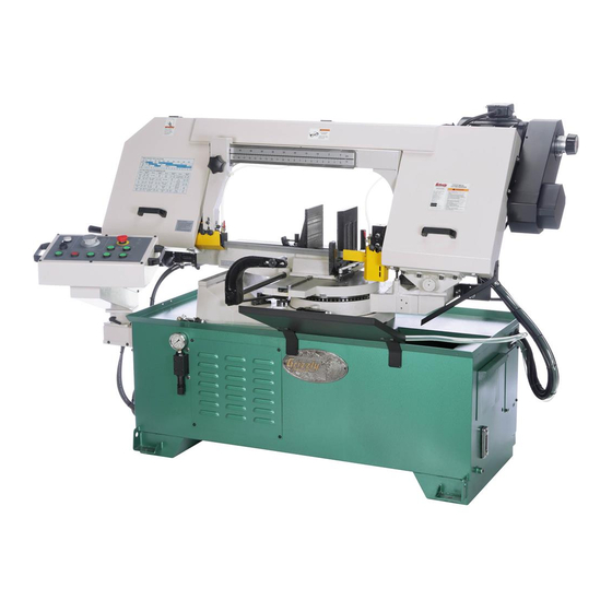
MODEL G0812
13" X 18" METAL-CUTTING BANDSAW
OWNER'S MANUAL
(For models manufactured since 2/16)
COPYRIGHT © JANUARY, 2017 BY GRIZZLY INDUSTRIAL, INC.
WARNING: NO PORTION OF THIS MANUAL MAY BE REPRODUCED IN ANY SHAPE
OR FORM WITHOUT THE WRITTEN APPROVAL OF GRIZZLY INDUSTRIAL, INC.
V1.01.17
#BL18559 PRINTED IN TAIWAN
Advertisement
Table of Contents

Related Manuals for Grizzly G0812


Summary of Contents for Grizzly G0812
- Page 1 (For models manufactured since 2/16) COPYRIGHT © JANUARY, 2017 BY GRIZZLY INDUSTRIAL, INC. WARNING: NO PORTION OF THIS MANUAL MAY BE REPRODUCED IN ANY SHAPE OR FORM WITHOUT THE WRITTEN APPROVAL OF GRIZZLY INDUSTRIAL, INC. V1.01.17 #BL18559 PRINTED IN TAIWAN...
- Page 2 This manual provides critical safety instructions on the proper setup, operation, maintenance, and service of this machine/tool. Save this document, refer to it often, and use it to instruct other operators. Failure to read, understand and follow the instructions in this manual may result in fire or serious personal injury—including amputation, electrocution, or death.
-
Page 3: Table Of Contents
Table of Contents INTRODUCTION ..........2 SECTION 6: MAINTENANCE ......42 Contact Info............ 2 Schedule ............42 Manual Accuracy ........... 2 Cleaning & Protecting ........42 Identification ........... 3 Lubrication ........... 42 Controls & Components ......... 4 Hydraulic System ......... 45 Machine Data Sheet ........ -
Page 4: Introduction
ID label (see below). This information is required for us to provide proper tech support, and it helps us determine if updated documenta- tion is available for your machine. Manufacture Date Serial Number Model G0812 (Mfd. Since 2/16) -
Page 5: Identification
Blade Tension Adjustment Handwheel Knob Auto Stop Vise Handwheel Adjustment Lever Coolant Control Valve Movable Fixed Vise Vise Jaw Vise Locks To reduce your risk of serious injury, read this entire manual BEFORE using machine. Model G0812 (Mfd. Since 2/16) -
Page 6: Controls & Components
IMPORTANT: For blade start button to work, hydraulic motor button (G) and vise STAND BY close button (J) must be pressed first, and headstock must be raised. Figure 1. Model G0812 control panel. Vise Close Button ( ): Hydraulically clos- << I START es vise to secure workpiece during cut. - Page 7 Q. Auto-Stop Adjustment Lever: Sets maxi- mum headstock height. Adjust by changing position of lower limit switch. This feature is useful for speeding up repetitive cuts by eliminating unnecessary headstock travel. R. Blade Tension Handwheel: Increases or decreases blade tension. Model G0812 (Mfd. Since 2/16)
-
Page 8: Machine Data Sheet
Machine Data Sheet MACHINE DATA SHEET Customer Service #: (570) 546-9663 · To Order Call: (800) 523-4777 · Fax #: (800) 438-5901 MODEL G0812 13" X 18" 2 HP INDUSTRIAL METAL CUTTING BANDSAW Product Dimensions: Weight................................1345 lbs. Width (side-to-side) x Depth (front-to-back) x Height................90 x 52 x 56 in. - Page 9 The information contained herein is deemed accurate as of 10/14/2019 and represents our most recent product specifications. Model G0812 PAGE 2 OF 3 Due to our ongoing improvement efforts, this information may not accurately describe items previously purchased. Model G0812 (Mfd. Since 2/16)
- Page 10 The information contained herein is deemed accurate as of 10/14/2019 and represents our most recent product specifications. Model G0812 PAGE 3 OF 3 Due to our ongoing improvement efforts, this information may not accurately describe items previously purchased. Model G0812 (Mfd. Since 2/16)
-
Page 11: Section 1: Safety
Never operate under the influence of drugs or injury or blindness from flying particles. Everyday alcohol, when tired, or when distracted. eyeglasses are NOT approved safety glasses. Model G0812 (Mfd. Since 2/16) - Page 12 Make sure they are properly installed, you experience difficulties performing the intend- undamaged, and working correctly BEFORE ed operation, stop using the machine! Contact our operating machine. Technical Support at (570) 546-9663. -10- Model G0812 (Mfd. Since 2/16)
-
Page 13: Additional Safety For
Spilled cutting fluid invites slip- HOT SURFACES. Contact with hot surfaces from ping hazards. machine components, ejections of hot chips, swarf, and the workpiece itself can cause burns. -11- Model G0812 (Mfd. Since 2/16) -
Page 14: Section 2: Power Supply
To reduce the risk of these hazards, avoid over- loading the machine during operation and make sure it is connected to a power supply circuit that meets the specified circuit requirements. -12- Model G0812 (Mfd. Since 2/16) - Page 15 Minimum Gauge Size ......12 AWG service personnel, and it must comply with Maximum Length (Shorter is Better)..50 ft. all local codes and ordinances. -13- Model G0812 (Mfd. Since 2/16)
-
Page 16: Section 3: Setup
Grizzly or the shipping agent. You MUST have the original pack- Box Inventory (Figure 7) aging to file a freight claim. -
Page 17: Cleanup
Repeat Steps 2–3 as necessary until clean, then coat all unpainted surfaces with a quality metal protectant to prevent rust. -15- Model G0812 (Mfd. Since 2/16) -
Page 18: Site Considerations
Shadows, glare, or strobe effects that may distract access restricted location. or impede the operator must be eliminated. Keep Area Unobstructed 88" Min. 30" for Maintenance Keep Area Unobstructed = Electrical Connection 100" Figure 9. Minimum working clearances. -16- Model G0812 (Mfd. Since 2/16) -
Page 19: Lifting & Placing
Figure 10. Inserting forklift forks for lifting machine. With an assistant helping to stabilize the load, lift machine just high enough to clear pallet and any floor obstacles, then place machine in final position on shop floor. -17- Model G0812 (Mfd. Since 2/16) -
Page 20: Anchoring To Floor
If the machine will be installed in a commercial or With the exception of the work stop rod, work workplace setting, or if it is permanently connect- stop, and splash guard, the Model G0812 comes ed (hardwired) to the power supply, local codes fully assembled from the factory. - Page 21 Fit splash guard over lip of base, as shown in Figure 17. Figure 14. Work stop arm attached to stop rod. Splash Guard Work Stop Figure 15. Stop rod flush with vise base casting. Figure 17. Splash guard installed over lip of base. -19- Model G0812 (Mfd. Since 2/16)
-
Page 22: Test Run
, G). You should hear hydraulic motor (located in machine base) turn ON. Check function of saw headstock hydraulics Figure 18. G0812 Control panel. by pressing raise headstock button ( , E) setting feed dial (B) at a number over "0", then pressing lower headstock button ( , F). - Page 23 , I). The machine should not start. 23. Press Emergency Stop button. Test Run is 18. Open blade cover and lock in position (see complete. Figure 21). This activates blade cover safety switch to prevent saw starting. HIGH STOP -21- Model G0812 (Mfd. Since 2/16)
-
Page 24: Recommended Adjustments
SECTION 7: SERVICE ADJUSTMENTS. Factory adjustments that should be verified: Downfeed Stop (Page 54). Blade Tracking (Page 28). Blade Guide Bearings (Page 55). Squaring Blade to Table (Page 56). -22- Model G0812 (Mfd. Since 2/16) -
Page 25: Section 4: Operations
Read books/magazines or get formal training before beginning any proj- ects. Regardless of the content in this sec- tion, Grizzly Industrial will not be held liable for accidents caused by lack of training. -23- Model G0812 (Mfd. Since 2/16) -
Page 26: Blade Selection
H. Blade Back: The distance between the bot- tom of the gullet and the back edge of the blade. Blade Pitch or TPI: The number of teeth per inch measured from gullet to gullet. -24- Model G0812 (Mfd. Since 2/16) - Page 27 Material Width/Diameter Teeth Per Inch (TPI) for Bandsaw Blades Material Shapes TOOTH SELECTION 1.5/.8 1.4/2.5 1.5/.8 1.4/2.5 inch 2½ 3½ 14 15 Figure 24. General guidelines for blade selection and speed chart. -25- Model G0812 (Mfd. Since 2/16)
-
Page 28: Changing Blade
Top Wheel Bottom Wheel brackets shown in Figure 25. Struts Bracket Bracket Wire Tension Blade Guide Wheel Handwheel Bearings Figure 27. Installing new blade. Figure 25. Wheel cover secured in "up" position. -26- Model G0812 (Mfd. Since 2/16) -
Page 29: Tensioning & Tracking Blade
Proper blade tension is essential to long blade directional arrow as a guide. life, straight cuts, and efficient cutting. The Model G0812 features a blade tension indicator to assist you with blade tensioning. The three major signs of incorrect blade tension... -
Page 30: Blade Breakage
Tracking Cap in contact with the workpiece when starting a Screw cut and at all times during cutting. Figure 32. Location of blade tracking cap screw. -28- Model G0812 (Mfd. Since 2/16) -
Page 31: Blade Care
(Refer to Blade Speed Chart on Page 30 and Chip Inspection Chart Model G0812 blade speeds: 95–380 FPM. on Page 31). Keep your blades clean, since dirty or gummed up blades pass through the cutting During operation, pay attention to the chips being... -
Page 32: Blade Speed Chart
Tool Steel (62) Steel (26) Cast Iron (98) Oil- Copper 229~482 203~213 85~203 Plastics & Hardened Stainless Alloy (70) (147) (62) (65) (26) (62) Lumber (67) Tool Steel Steel Figure 34. Dry-cutting blade speed chart. -30- Model G0812 (Mfd. Since 2/16) -
Page 33: Chip Inspection Chart
& curled tightly powdery Figure 35. Chip inspection chart. thin & curled tightly powdery powdery thin & curled tightly thin & curled tightly thin & curled tightly thin & curled tightly thin & curled tightly -31- Model G0812 (Mfd. Since 2/16) -
Page 34: Feed Rate
Feed Rate Work Stop The speed at which the saw blade will cut through The Model G0812 is equipped with a work stop for a workpiece is controlled by blade type, feed rate, repetitive cutting operations up to 16" long. - Page 35 Loosen work stop knob (see Figure 40), and adjust horizontal position of hex bolt relative to end of workpiece, then tighten cap screw and knob. Hex Bolt Work Stop Knob Scale Screw Figure 40. Work stop set for repetitive cutting operation. -33- Model G0812 (Mfd. Since 2/16)
-
Page 36: Vise
Loosen two vise locks at base of vise (see Figure 43). The Model G0812 vise can be positioned on either side of the machine to perform a variety of straight or angle cuts. After the movable vise jaw is manually positioned near the workpiece, the... - Page 37 START STOP stock must be raised before saw motor and Figure 47. Movable vise positioned for angled blade will start. workpiece. Tighten movable vise against workpiece, HIGH then tighten lock bolt. HIGH STOP STOP -35- Model G0812 (Mfd. Since 2/16)
-
Page 38: Angle Cuts
Headstock ing operation, then tighten swivel lock handle and secure vise. Install splash guard (and work stop if desired) Vise on left side. Figure 49. Headstock positioned for cuts to right. -36- Model G0812 (Mfd. Since 2/16) -
Page 39: Blade Guides
Figure 52. Blade guides. The right blade guide has a wire brush that makes contact with the blade to help clear away chips and extend blade life (see Figure 53). Blade Brush Figure 53. Blade brush. -37- Model G0812 (Mfd. Since 2/16) -
Page 40: Coolant
STOP when handling coolant and Coolant follow federal, state, and Control fluid manufacturer require- Valve ments to properly dispose (1 of 2) of coolant. HIGH STOP Figure 54. Coolant valve (1 of 2) open. -38- Model G0812 (Mfd. Since 2/16) -
Page 41: Operation Tips
Figure 56. Example of spray gun in use. STOP • Use coolant when possible to increase blade life. Loosen blade tension at the end of each day to prolong blade life. -39- Model G0812 (Mfd. Since 2/16) -
Page 42: Workpiece Inspection
Unstable Workpieces: Workpieces that can- • not be properly supported or stabilized with the vise should not be cut on this bandsaw. Examples are chains, cables, workpieces with internal or built-in moving or rotating parts, etc. -40- Model G0812 (Mfd. Since 2/16) -
Page 43: Section 5: Accessories
Can be used on all metals except To reduce this risk, only install accessories titanium. recommended for this machine by Grizzly. NOTICE Refer to our website or latest catalog for additional recommended accessories. -
Page 44: Section 6: Maintenance
Blade & Guides 8 Hrs. Table & Vise 8 Hrs. Vise Leadscrew 40 Hrs. Gearbox 50 Hrs. Headstock Pivot Point 8 Hrs. Figure 62. Recommended lubrication tasks. Figure 61. Recommended products for machine lubrication. -42- Model G0812 (Mfd. Since 2/16) - Page 45 Place one or two drops of light machine oil on blade and guides daily, especially when cutting cast iron, as no coolant is recommended. Guides Leadscrew Figure 66. Vise leadscrew lubrication area. Blade Figure 64. Blade and guide lubrication points. -43- Model G0812 (Mfd. Since 2/16)
- Page 46 Sight Glass Figure 67. Gearbox fill plug and sight glass. Place drain pan under drain plug, then remove drain plug (see Figure 68) and drain oil. Drain Plug Figure 68. Location of drain plug. -44- Model G0812 (Mfd. Since 2/16)
-
Page 47: Hydraulic System
Remove front access panel (see Figure 70). Fluid Gauge Slide tank out, then place it on blocks high Figure 71. Hydraulic tank fluid gauge and fill cap enough to get drain plug over drain pan. location. -45- Model G0812 (Mfd. Since 2/16) - Page 48 Open tank by removing hex bolts that secure lid (see Figure 73). Tank Screen Tank Figure 73. Hydraulic fluid tank lid removed to access for cleaning. -46- Model G0812 (Mfd. Since 2/16)
-
Page 49: Tensioning/Replacing Belt
Follow Steps 4–5 in Tensioning Belt proce- dure to set correct belt tension. Re-install belt cover so bracket aligns with slot (see Figure 74), then re-install variable- speed covers. Pivot Brackets Figure 75. Motor pivot bracket location. -47- Model G0812 (Mfd. Since 2/16) -
Page 50: Coolant System Service
BIOLOGICAL & POISON HAZARD! Figure 78. Approximate maximum fill line on Use correct personal filter screen. protection equipment when handling coolant. Replace chip collection drawer. Follow federal, state, and fluid manufacturer requirements for proper disposal. -48- Model G0812 (Mfd. Since 2/16) - Page 51 Remove drain plug (see Figure 79), empty tank contents into drain pan, and dispose of fluid following federal, state, and fluid manu- facturer requirements. Chip Collection Drawer Drain Plug Figure 79. Coolant drain plug location. -49- Model G0812 (Mfd. Since 2/16)
-
Page 52: Machine Storage
Re-tension blade as described on Page 27. Repeat Test Run on Page 20. Add coolant, as described in Coolant System Service on Page 48. -50- Model G0812 (Mfd. Since 2/16) -
Page 53: Section 7: Service
3. V-Belt worn or loose. 3. Inspect/replace belt (Page 47). 4. Motor fan rubbing on fan cover. 4. Fix/replace fan cover; replace loose/damaged fan. 5. Pulley loose. 5. Re-align/replace shaft, pulley, set screw, and key. -51- Model G0812 (Mfd. Since 2/16) - Page 54 Blade keeps moving 1. Upper limit switch not engaged/at fault. or headstock not raising after cut. 1. Adjust lower limit switch position (Page 57). Headstock not 1. Lower limit switch position incorrect. raising to desired height. -52- Model G0812 (Mfd. Since 2/16)
- Page 55 (indicated by red LED in solenoid plug). 1. Replace hydraulic fluid (Page 45). Hydraulic tank fluid 1. Hydraulic fluid is old or contaminated with water. burnt or has tan discoloration. -53- Model G0812 (Mfd. Since 2/16)
-
Page 56: Blade Brush
Blade Brush Downfeed Stop Bolt The Model G0812 has a blade brush to help keep The Model G0812 has an adjustable stop bolt to metal chips off the blade wheels. It will wear over help support the headstock at the bottom of its time and require re-adjustment when it no longer travel. -
Page 57: Blade Guide Bearings
Adjust blade guide bearings on right blade Direction guide assembly in same manner, then re- to Move Support install blade guards. Assembly Bearing Figure 82. Support bearing touching blade. -55- Model G0812 (Mfd. Since 2/16) -
Page 58: Squaring Blade With Table
Tip: Cut small section from scrap piece of material with known square end and mea- sure for uniform thickness. If thickness is not Square uniform, repeat adjustments above until your personal requirements are met. Figure 84. Checking blade-to-table squareness. -56- Model G0812 (Mfd. Since 2/16) -
Page 59: Limit Switches
Turn tension handwheel counterclockwise ⁄ turn. The motor should turn OFF. If it does Figure 87. Headstock stopped against downfeed not, adjust switch closer to plate and repeat stop bolt. Steps 3–5. DISCONNECT MACHINE FROM POWER! -57- Model G0812 (Mfd. Since 2/16) -
Page 60: Angle Stops
Stop Bolt Raise headstock. It should automatically stop at approximate height previously set on scale. Adjust limit switch position as needed to fine tune the height setting for your workpiece. Figure 91. Flip-stop engaged. -58- Model G0812 (Mfd. Since 2/16) - Page 61 Blade should be square to vise. Figure 95. Using 60° square to check 45° stop. Repeat Steps 6–7 as necessary, then tighten jam nut against stop block (see Figure 93) without turning stop bolt. -59- Model G0812 (Mfd. Since 2/16)
- Page 62 Slide vise to right position and secure it. Refer to Changing Vise Position on Page 34. Connect machine to power and lower head- stock all the way until it stops moving. -60- Model G0812 (Mfd. Since 2/16)
-
Page 63: Section 8: Wiring
Technical Support at (570) 546-9663. The photos and diagrams included in this section are best viewed in color. You can view these pages in color at www.grizzly.com. -61- Model G0812 (Mfd. Since 2/16) -
Page 64: Electrical Overview
Component Locations Main Motor Control Panel Blade Cover Limit Switch Coolant Saw Down Pump Limit Switch Saw Up Limit Switch Electrical Panel Hydraulic Blade Tension Pump Limit Switch READ ELECTRICAL SAFETY -62- Model G0812 (Mfd. Since 2/16) ON PAGE 61! -
Page 65: Electrical Panel Photo
Electrical Panel Photo Figure 98. Electrical panel wiring. READ ELECTRICAL SAFETY -63- Model G0812 (Mfd. Since 2/16) ON PAGE 61! -
Page 66: Electrical Panel Wiring Diagram
Electrical Panel Wiring Diagram READ ELECTRICAL SAFETY -64- Model G0812 (Mfd. Since 2/16) ON PAGE 61! -
Page 67: Control Panel Wiring
DOWN Switch Button Button NHD CB-10 NHD CB-01 NHD CB-01 E-Stop Button Power KEDU HY57B Lamp NHD NLD-22 To Electrical Panel Pages 63–64 Figure 99. Control panel wiring. READ ELECTRICAL SAFETY -65- Model G0812 (Mfd. Since 2/16) ON PAGE 61! -
Page 68: Main Motor Wiring
Figure 102. Main motor circuit breaker wiring. start capacitor wiring. Hydraulic Pump Wiring HYDRAULIC Start Capacitor PUMP 200MFD 220V 250VAC Ground Figure 103. Hydraulic pump wiring. To Electrical Panel Pages 63–64 READ ELECTRICAL SAFETY -66- Model G0812 (Mfd. Since 2/16) ON PAGE 61! -
Page 69: Coolant Pump Wiring
Coolant Pump Wiring COOLANT PUMP 220V To Electrical Panel Pages 63–64 Capacitor Figure 104. Coolant pump wiring. 3MFD 450VAC Ground READ ELECTRICAL SAFETY -67- Model G0812 (Mfd. Since 2/16) ON PAGE 61! -
Page 70: Limit Switch Wiring
Pages 63–64 AZD-1122 Limit Switch Shinozaki Limit Switch AZD-1112 Shinozaki AZD-1122 Figure 108. Blade tension limit switch wiring. Figure 106. Electrical Panel Saw Up limit Pages 63–64 switch wiring. READ ELECTRICAL SAFETY -68- Model G0812 (Mfd. Since 2/16) ON PAGE 61! -
Page 71: Hydraulic System Diagram
Hydraulic System Diagram FEED RATE CONTROL VALVE VISE JAW SAW BOW HYDRAULIC FLUID RESERVOIR HYDRAULIC PUMP MOTOR PUMP SUCTION FILTER HYDRAULIC MANIFOLD FILL PRESSURE GAUGE PRESSURE GAUGE READ ELECTRICAL SAFETY -69- Model G0812 (Mfd. Since 2/16) ON PAGE 61! -
Page 72: Section 9: Parts
Please Note: We do our best to stock replacement parts whenever possible, but we cannot guarantee that all parts shown here are available for purchase. Call (800) 523-4777 or visit our online parts store at www.grizzly.com to check for availability. - Page 73 P0812096 VALVE ASSEMBLY P0812044 FLAT WASHER 10MM P0812097 SET SCREW M6-1 X 10 P0812045 KNOB BOLT M10-1.5 X 60 6-LOBE P0812098 HOSE CLAMP 1/2" P0812046 CAP SCREW M8-1.25 X 40 P0812099 LEADSCREW GUIDE PLATE -71- Model G0812 (Mfd. Since 2/16)
-
Page 74: Drive Wheel & Motor
101-9 140 141 173-9 173-8 173-7 173-16 173-17 173-10 173-15 173-6 173-14 173-11 173-18 173-20 166-1 160-5 173-21 161-1 173-22 173-19 166-2 160-1 173-2 161-2 160-4 173-4 173-5 166-3 160-3 161-3 173-3 160-2 173-1 -72- Model G0812 (Mfd. Since 2/16) - Page 75 HEX SOCKER HEADLESS SCREW M8 X 25L P0812177 CROSS ROUND HEAD SCREW M5 X 5L P0812146 ARM (RIGHT) P0812178 PIVOT PIN P0812147 NET TUBE ID1/4" X 2.2T X 143CM P0812179 LIMIT SWITCH P0812148 HOSE CLAMP 12MM -73- Model G0812 (Mfd. Since 2/16)
-
Page 76: Base & Vise
Base & Vise 246 247 287-8 287-5 287-6 287-7 287-4 287-2 287-3 265 266 287-5 287-1 287-5 353 354 315-7 315-1 315-3 315-2 315-4 315-9 315-8 315-10 315-11 -74- Model G0812 (Mfd. Since 2/16) - Page 77 P0812303 FLAT WASHER 6MM P0812254 CAP SCREW M8-1.25 X 45 P0812304 FLAT WASHER 6MM P0812255 CAP SCREW M10-1.5 X 35 P0812305 CAP SCREW M6-1 X 12 P0812256 LOCK WASHER 10MM P0812306 COOLANT PUMP BRACKET -75- Model G0812 (Mfd. Since 2/16)
- Page 78 FLAT WASHER 8MM P0812370 BRACKET P0812333 CONTROL BOX MOUNT P0812371 CAP SCREW M8-1.25 X 25 P0812334 CAP SCREW M8-1.25 X 20 P0812372 CONTROL PEDESTAL SUPPORT COVER P0812335 FLAT WASHER 8MM P0812373 SET SCREW M8-1.25 X 8 -76- Model G0812 (Mfd. Since 2/16)
-
Page 79: Electrical
SAW DOWN BUTTON NHD CB-01 P0812419 CONTACTOR KEDU JD6.10 P0812409 POWER LAMP NHD NLD-22 P0812420 CIRCUIT BOARD RF-0350-200801 P0812410 E-STOP BUTTON KEDU HY57B P0812421 TERMINAL BAR P0812411 LIMIT SWITCH (UPPER LEFT) AZD-1122 P0812422 TERMINAL -77- Model G0812 (Mfd. Since 2/16) -
Page 80: Labels & Cosmetics
Safety labels help reduce the risk of serious injury caused by machine hazards. If any label comes off or becomes unreadable, the owner of this machine MUST replace it in the original location before resuming operations. For replacements, contact (800) 523-4777 or www.grizzly.com. -78-... - Page 81 Would you recommend Grizzly Industrial to a friend? _____ Yes _____No Would you allow us to use your name as a reference for Grizzly customers in your area? Note: We never use names more than 3 times. _____ Yes _____No 10.
- Page 82 FOLD ALONG DOTTED LINE Place Stamp Here GRIZZLY INDUSTRIAL, INC. P.O. BOX 2069 BELLINGHAM, WA 98227-2069 FOLD ALONG DOTTED LINE Send a Grizzly Catalog to a friend: Name_______________________________ Street_______________________________ City______________State______Zip______ TAPE ALONG EDGES--PLEASE DO NOT STAPLE...
-
Page 83: Warranty & Returns
WARRANTY & RETURNS Grizzly Industrial, Inc. warrants every product it sells for a period of 1 year to the original purchaser from the date of purchase. This warranty does not apply to defects due directly or indirectly to misuse, abuse, negligence, accidents, repairs or alterations or lack of maintenance.
Need help?
Do you have a question about the G0812 and is the answer not in the manual?
Questions and answers