Table of Contents
Advertisement
Quick Links
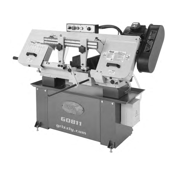
MODEL G0811
9" X 16" METAL-CUTTING BANDSAW
OWNER'S MANUAL
(For models manufactured since 02/16)
COPYRIGHT © NOVEMBER, 2016 BY GRIZZLY INDUSTRIAL, INC.
WARNING: NO PORTION OF THIS MANUAL MAY BE REPRODUCED IN ANY SHAPE
OR FORM WITHOUT THE WRITTEN APPROVAL OF GRIZZLY INDUSTRIAL, INC.
V1.02.17
#BL18346 PRINTED IN TAIWAN
Advertisement
Table of Contents

Related Manuals for Grizzly G0811


Summary of Contents for Grizzly G0811
- Page 1 (For models manufactured since 02/16) COPYRIGHT © NOVEMBER, 2016 BY GRIZZLY INDUSTRIAL, INC. WARNING: NO PORTION OF THIS MANUAL MAY BE REPRODUCED IN ANY SHAPE OR FORM WITHOUT THE WRITTEN APPROVAL OF GRIZZLY INDUSTRIAL, INC. V1.02.17 #BL18346 PRINTED IN TAIWAN...
- Page 2 This manual provides critical safety instructions on the proper setup, operation, maintenance, and service of this machine/tool. Save this document, refer to it often, and use it to instruct other operators. Failure to read, understand and follow the instructions in this manual may result in fire or serious personal injury—including amputation, electrocution, or death.
-
Page 3: Table Of Contents
Table of Contents INTRODUCTION ..........2 SECTION 6: MAINTENANCE ......41 Contact Info............ 2 Schedule ............41 Manual Accuracy ........... 2 Cleaning & Protecting ........41 Identification ........... 3 Lubrication ........... 41 Controls & Components ......... 4 Inspecting V-Belt .......... 43 Machine Data Sheet ........ -
Page 4: Introduction
ID label (see below). This information is required for us to provide proper tech support, and it helps us determine if updated documenta- tion is available for your machine. Manufacture Date Serial Number Model G0811 (Mfd. Since 02/16) -
Page 5: Identification
Electrical Box Work Stop Rod Blade Tension Gauge Rear View Blade Tension Knob Vise Handwheel Fixed Vise Movable Vise Coolant Tank To reduce your risk of serious injury, read this entire manual BEFORE using machine. Model G0811 (Mfd. Since 02/16) -
Page 6: Controls & Components
Work Stop: Quickly positions workpiece dur- ing repetitive cutting operations. Vise Table Figure 1. Model G0811 control panel. A. Coolant Pump Switch: Turns coolant tank pump ON, enabling flow to coolant valves (see Identification on Page 3). -
Page 7: Machine Data Sheet
MACHINE DATA SHEET Customer Service #: (570) 546-9663 · To Order Call: (800) 523-4777 · Fax #: (800) 438-5901 MODEL G0811 9" X 16" METAL‐CUTTING BANDSAW Product Dimensions: Weight................................617 lbs. Width (side-to-side) x Depth (front-to-back) x Height............62-1/2 x 22-1/2 x 45-1/2 in. - Page 8 The information contained herein is deemed accurate as of 2/13/2017 and represents our most recent product specifications. Model G0811 PAGE 2 OF 2 Due to our ongoing improvement efforts, this information may not accurately describe items previously purchased. Model G0811 (Mfd. Since 02/16)
-
Page 9: Section 1: Safety
Everyday ery. Never operate under the influence of drugs or eyeglasses are NOT approved safety glasses. alcohol, when tired, or when distracted. Model G0811 (Mfd. Since 02/16) - Page 10 EXPERIENCING DIFFICULTIES. If at any time debris. Make sure they are properly installed, you experience difficulties performing the intend- undamaged, and working correctly BEFORE ed operation, stop using the machine! Contact our operating machine. Technical Support at (570) 546-9663. Model G0811 (Mfd. Since 02/16)
-
Page 11: Additional Safety For Horizontal
HOT SURFACES. Contact with hot surfaces from port fixture. Flag long pieces to avoid a tripping hazard. Never hold the workpiece with your hands machine components, ejections of hot chips, during a cut. swarf, and the workpiece itself can cause burns. Model G0811 (Mfd. Since 02/16) -
Page 12: Section 2: Power Supply
To reduce the risk of these hazards, avoid over- loading the machine during operation and make sure it is connected to a power supply circuit that meets the specified circuit requirements. -10- Model G0811 (Mfd. Since 02/16) -
Page 13: Grounding Requirements
Minimum Gauge Size ......14 AWG all local codes and ordinances. Maximum Length (Shorter is Better)..50 ft. -11- Model G0811 (Mfd. Since 02/16) -
Page 14: Section 3: Setup
IMPORTANT: Save all packaging materials until you are completely satisfied with the machine and have resolved any issues between Grizzly or the shipping agent. You MUST have the original pack- aging to file a freight claim. It is also extremely helpful if you need to return your machine later. -
Page 15: Hardware Recognition Chart
Hardware Recognition Chart USE THIS CHART TO MATCH UP HARDWARE DURING THE INVENTORY AND ASSEMBLY PROCESS. Flat Head Screw -13- Model G0811 (Mfd. Since 02/16) -
Page 16: Inventory
Lock Washers 8mm (Motor) ....... 4 • Button Head Cap Screw M6-1 x 10 (Pulley Cover) ..........1 • Hex Bolts M8-1.25 x 20 (Pulley Cover)..2 • Flat Washers 8mm (Pulley Cover) ....2 -14- Model G0811 (Mfd. Since 02/16) -
Page 17: Cleanup
Figure 6. T23692 Orange Power Degreaser. Repeat Steps 2–3 as necessary until clean, then coat all unpainted surfaces with a quality metal protectant to prevent rust. -15- Model G0811 (Mfd. Since 02/16) -
Page 18: Site Considerations
73" Min. 30" for Maintenance Keep Workpiece Loading Area Unobstructed " Keep Workpiece = Electrical Connection Loading Area With headstock in “up” position. Unobstructed Figure 7. Minimum working clearances. -16- Model G0811 (Mfd. Since 02/16) -
Page 19: Lifting & Placing
Power Lifting Lifting 10. Tighten hex nuts against frame to secure lev- Equipment Strap eling hex bolts. Front Lifting Strap Round Steel Bar In Lifting Holes Figure 8. Lifting machine with forklift and lifting slings. -17- Model G0811 (Mfd. Since 02/16) -
Page 20: Anchoring To Floor
(see Figure 12). Flat Washer Machine Base Lag Shield Anchor Concrete Drilled Hole Figure 10. Popular method for anchoring machinery to a concrete floor. Motor Mount Plate Figure 12. Motor attached to motor mount plate. -18- Model G0811 (Mfd. Since 02/16) - Page 21 Loosen knurled belt tension knob (see Figure 14) until motor lowers no farther, then roll V-belt onto pulleys. Belt Knob Tension Knob Figure 16. Pulley cover secured with knob. Figure 14. Belt tension knob location. -19- Model G0811 (Mfd. Since 02/16)
-
Page 22: Test Run
To test run machine: Clear all setup tools away from machine. Raise headstock all the way up, and turn feed rate dial (see Figure 18) clockwise to "0". Press Emergency Stop button (see Figure 18). -20- Model G0811 (Mfd. Since 02/16) - Page 23 Figure 20. Coolant control valve open. correctly. — If machine does start, immediately turn it OFF and disconnect power. Safety feature of Emergency Stop button is NOT working properly and must be replaced before fur- ther using machine. -21- Model G0811 (Mfd. Since 02/16)
-
Page 24: Recommended Adjustments
SECTION 7: SERVICE. Factory adjustments that should be verified: Blade Tracking (Page 49). Blade Guide Bearings (Page 50). Figure 21. Coolant pump switch location. Squaring Blade to Table (Page 51). -22- Model G0811 (Mfd. Since 02/16) -
Page 25: Section 4: Operations
Read books/magazines or get formal training before beginning any proj- ects. Regardless of the content in this sec- tion, Grizzly Industrial will not be held liable for accidents caused by lack of training. -23- Model G0811 (Mfd. Since 02/16) -
Page 26: Blade Selection
H. Blade Back: The distance between the bot- tom of the gullet and the back edge of the blade. Blade Pitch or TPI: The number of teeth per inch measured from gullet to gullet. -24- Model G0811 (Mfd. Since 02/16) - Page 27 Material Width/Diameter Teeth Per Inch (TPI) for Bandsaw Blades Material Shapes TOOTH SELECTION 1.5/.8 1.4/2.5 1.5/.8 1.4/2.5 inch 2½ 3½ 14 15 Figure 24. General guidelines for blade selection and speed chart. -25- Model G0811 (Mfd. Since 02/16)
-
Page 28: Changing Blade
Roller Bearings Figure 27. Installing new blade. Knobs Figure 25. Location of upper and lower blade guards. Loosen or remove knobs that secure upper and lower guards shown in Figure 25, then remove both guards. -26- Model G0811 (Mfd. Since 02/16) -
Page 29: Tensioning Blade
10. Re-install upper and lower blade guards, and Section close wheel covers. 11. Reposition blade guide arms (refer to Blade Guide Arms on Page 35 for details). Figure 31. Tension setting for 1" wide blades. -27- Model G0811 (Mfd. Since 02/16) -
Page 30: Blade Breakage
Reduce feed pressure by half for first 50–100 of material cut. To avoid twisting blade when cutting, adjust feed pressure when total width of blade is in cut. -28- Model G0811 (Mfd. Since 02/16) -
Page 31: Blade Speed
The Model G0811 has four speed settings—114, 196, 288, and 377 feet per minute (FPM). Refer to the chart on Page 30 for cutting speed recom- mendations by material type. -
Page 32: Blade Speed Chart
(62) Steel (26) Cast Iron (98) Oil- Copper 229~482 203~213 85~203 Plastics & Hardened Stainless Alloy (70) (147) (62) (65) (26) (62) Lumber (67) Tool Steel Steel Figure 35. Dry cutting blade speed chart. -30- Model G0811 (Mfd. Since 02/16) -
Page 33: Chip Inspection Chart
& curled tightly powdery Figure 36. Chip inspection chart. thin & curled tightly powdery powdery thin & curled tightly thin & curled tightly thin & curled tightly thin & curled tightly thin & curled tightly -31- Model G0811 (Mfd. Since 02/16) -
Page 34: Feed Rate
Page 31. Feed Rate Dial Work Stop The Model G0811 is equipped with a work stop that can be used to quickly position the workpiece during a repetitive cutting operation. Adjust the Figure 37. Location of feed rate dial. -
Page 35: Vise
Lock Handwheel Bolt Figure 41. Example of work holding options by material shape. Lock Scale Handle Figure 40. Location of vise components. Tools Needed Hex Wrench 3mm ..........1 Hex Wrench 4mm ..........1 -33- Model G0811 (Mfd. Since 02/16) - Page 36 Repeat Steps 1–2 as necessary, then tighten set screw above 90° stop screw. Tighten movable vise against workpiece, then tighten lock bolt. Loosen lock handle and swing fixed jaw until 45° stop screw contacts lock handle base. -34- Model G0811 (Mfd. Since 02/16)
-
Page 37: Blade Guide Arms
BIOLOGICAL AND POISON HAZARD! Use proper per- sonal protection equipment when handling coolant and follow federal, state, and fluid manufacturer require- ments to properly dispose of coolant. -35- Model G0811 (Mfd. Since 02/16) -
Page 38: Coolant System
Figure 46. Filter screen and hose installed. recycle to pump reservoir. NEVER operate pump with reservoir below low mark or you Add coolant (refer to Adding Coolant on will overheat pump and void warranty! Page 44). -36- Model G0811 (Mfd. Since 02/16) -
Page 39: Operation Tips
Loosen blade tension at the end of each day to prolong blade life. • Chips should be curled and silvery. If the chips are thin and powder-like, increase your feed rate. -37- Model G0811 (Mfd. Since 02/16) -
Page 40: Section 5: Accessories
Can be used on all metals except To reduce this risk, only install accessories titanium. recommended for this machine by Grizzly. Installing unapproved accessories may cause machine to malfunction, resulting in serious personal injury or machine damage. - Page 41 1000 Lb. Capacity! venient and rugged. Figure 53. D2271 Shop Fox ® Roller Table. Figure 55. D2273 and D2274 single and 5 roller stands. www.grizzly.com 1-800-523-4777 order online at or call -39- Model G0811 (Mfd. Since 02/16)
- Page 42 2", 3", steel and aluminum and one for brass and cast 4" & 6" squares. iron. Figure 57. G5618 Deburring Tool. Figure 59. H2993 4-Pc. Square Set. www.grizzly.com 1-800-523-4777 order online at or call -40- Model G0811 (Mfd. Since 02/16)
-
Page 43: Section 6: Maintenance
Keep unpainted cast iron surfaces rust-free with For optimum performance from your machine, regular applications of ISO 68 way oil (see follow this maintenance schedule and refer to any Page 38 for offerings from Grizzly). specific instructions given in this section. Daily: Lubrication •... - Page 44 Place one or two drops of light machine oil on Leadscrew blade and guides daily, especially when cutting cast iron, as no coolant is recommended. Guides Figure 64. Vise leadscrew lubrication area. Blade Figure 62. Blade and guide lubrication points. -42- Model G0811 (Mfd. Since 02/16)
-
Page 45: Inspecting V-Belt
Figure 66. Location of drain plug. Re-install drain plug, remove drain pan, then lower headstock to its lowest position. Fill gearbox with oil until oil level is at halfway point in sight glass, then replace fill plug. -43- Model G0811 (Mfd. Since 02/16) -
Page 46: Coolant System Service
BIOLOGICAL & POISON soapy water. HAZARD! Use correct personal When dry, refill tank with coolant. protection equipment when handling coolant. Replace filter screen and return hose. Follow federal, state, and fluid manufacturer requirements for proper disposal. -44- Model G0811 (Mfd. Since 02/16) -
Page 47: Machine Storage
Remove old coolant, then add a few drops of from electrical box. way oil and blow out lines with compressed air. Repeat Test Run on Page 20. Add coolant, as described in Coolant System Service on Page 44. -45- Model G0811 (Mfd. Since 02/16) -
Page 48: Section 7: Service
7. Machine incorrectly mounted to floor. 7. Tighten mounting bolts; relocate/shim machine. 8. Motor bearings at fault. 8. Test by rotating shaft; rotational grinding/loose shaft requires bearing replacement. 9. Gearbox at fault. 9. Rebuild gearbox for bad gear(s)/bearing(s). -46- Model G0811 (Mfd. Since 02/16) - Page 49 2. Guide bearings out of adjustment; guide 2. Re-adjust (Page 35, 50)/replace. arms too far from workpiece. 3. Blade tension too low. 3. Increase blade tension (Page 27). 4. Blade dull. 4. Replace blade (Page 26). -47- Model G0811 (Mfd. Since 02/16)
-
Page 50: Blade Brush
Blade Brush Limit Switch Stop Bolt The Model G0811 has a blade brush to help keep metal chips off the blade wheels. It will wear over The limit switch stop bolt will need to be adjusted time and require re-adjustment when it no longer if the machine does not turn OFF after it com- contacts the blade. -
Page 51: Blade Tracking
(see Figure 71), Close wheel covers. blade is tracking properly and no adjust- ments are needed. Go to Step 6. Shoulder Blade Figure 71. Blade tracking properly against idler wheel shoulder. -49- Model G0811 (Mfd. Since 02/16) -
Page 52: Blade Guide Bearings
Adjust blade guide bearings on left blade Backing guide arm in same manner. Bearing Re-install blade guard onto left blade arm. Figure 73. Backing bearing touching blade. Repeat Step 5 for left blade guide arm. -50- Model G0811 (Mfd. Since 02/16) -
Page 53: Squaring Blade To Table
Tip: Cut small section from scrap piece of material with known square end and mea- sure for uniform thickness. If thickness is not uniform, repeat adjustments above until your personal requirements are met. -51- Model G0811 (Mfd. Since 02/16) -
Page 54: Section 8: Wiring
Technical Support at (570) 546-9663. The photos and diagrams included in this section are best viewed in color. You can view these pages in color at www.grizzly.com. -52- Model G0811 (Mfd. Since 02/16) -
Page 55: Electrical Overview
Pages 54–55 54–55 Motor Pages 54–55 Electrical Panel Pages 54–55 Coolant Pump Pages 54–55 6-15 Plug Ground Component Locations Motor Control Panel Limit Switch Coolant Pump Electrical Panel READ ELECTRICAL SAFETY -53- Model G0811 (Mfd. Since 02/16) ON PAGE 52! -
Page 56: Wiring Diagram
OL Relay TECO RHU-10/16k1 Ground TRIP IND. TEST 12 11.3 RESET 97 NO 98 NO 95 NC 96 NC PUMP Ground MOTOR 220V To Power Cord Page 53 READ ELECTRICAL SAFETY -54- Model G0811 (Mfd. Since 02/16) ON PAGE 52! -
Page 57: Wiring Photos
Figure 80. Motor wiring. Figure 77. Electrical panel wiring. Figure 81. Circuit breaker wiring. Figure 78. Control panel wiring. Figure 82. Coolant pump wiring. Figure 79. Limit switch wiring. READ ELECTRICAL SAFETY -55- Model G0811 (Mfd. Since 02/16) ON PAGE 52! -
Page 58: Section 9: Parts
SECTION 9: PARTS We do our best to stock replacement parts when possible, but we cannot guarantee that all parts shown are available for purchase. Call (800) 523-4777 or visit www.grizzly.com/parts to check for availability. Stand & Base 16-9 16-8... - Page 59 P0811022 LEADSCREW NUT BRACKET P0811074 EXT TOOTH WASHER 6MM P0811023 DOWEL PIN 5 X 34 P0811075 PHLP HD SCR M4-.7 X 30 P0811024 CAP SCREW M10-1.5 X 25 P0811076 SET SCREW M8-1.25 X 14 -57- Model G0811 (Mfd. Since 02/16)
-
Page 60: Frame & Motor
254-8 254-1 238-6 238-7 254-6 254-2 238-9 254-7 254-3 233 234 254-4 254-10 254-5 248 249 256 257 120-6 213 214 120-5 120-4 120-8 120-1 120-7 120-2 120-3 122-2 122-1 122-4 122-3 122-5 109-1 -58- Model G0811 (Mfd. Since 02/16) - Page 61 MICRO CONTROL BLOCK 1/4" X 1/2" (90 DEG) P0811210 IDLER WHEEL 1-1/8" X 12" 254-4 P0811254-4 HOSE CLAMP 1/2" P0811211 IDLER SHAFT 254-5 P0811254-5 COOLANT HOSE 1/4" X 3/32" X 32" P0811212 HANDLE M10-1.5 X 16, 112L 254-6 P0811254-6 3-WAY VALVE -59- Model G0811 (Mfd. Since 02/16)
- Page 62 SLIDING PLATE P0811293 CAP SCREW M6-1 X 10 P0811270 LOCK WASHER 8MM P0811294 HANDLE M12-1.75 X 10, 97L P0811271 CAP SCREW M8-1.25 X 10 P0811295 BLADE TENSION SCALE P0811272 HEX BOLT M6-1 X 12 -60- Model G0811 (Mfd. Since 02/16)
-
Page 63: Electrical Components
POWER CORD 14G 3W 72" 6-15P P0811309 E-STOP KEDU HY57B 22MM P0811319 LIMIT SWITCH CORD 18G 2W 36" P0811310 PUMP SWITCH NHD CB-10 22MM P0811320 STRAIN RELIEF TYPE-3 PG11 P0811311 POWER SWITCH NHD CB-10 22MM P0811322 DIN RAIL 3-1/2" -61- Model G0811 (Mfd. Since 02/16) -
Page 64: Labels & Cosmetics
Safety labels help reduce the risk of serious injury caused by machine hazards. If any label comes off or becomes unreadable, the owner of this machine MUST replace it in the original location before resuming operations. For replacements, contact (800) 523-4777 or www.grizzly.com. -62-... -
Page 65: Warranty Card
Would you recommend Grizzly Industrial to a friend? _____ Yes _____No Would you allow us to use your name as a reference for Grizzly customers in your area? Note: We never use names more than 3 times. _____ Yes _____No 10. - Page 66 FOLD ALONG DOTTED LINE Place Stamp Here GRIZZLY INDUSTRIAL, INC. P.O. BOX 2069 BELLINGHAM, WA 98227-2069 FOLD ALONG DOTTED LINE Send a Grizzly Catalog to a friend: Name_______________________________ Street_______________________________ City______________State______Zip______ TAPE ALONG EDGES--PLEASE DO NOT STAPLE...
-
Page 67: Warranty & Returns
WARRANTY & RETURNS Grizzly Industrial, Inc. warrants every product it sells for a period of 1 year to the original purchaser from the date of purchase. This warranty does not apply to defects due directly or indirectly to misuse, abuse, negligence, accidents, repairs or alterations or lack of maintenance.
Need help?
Do you have a question about the G0811 and is the answer not in the manual?
Questions and answers